TOYOTA COROLLA 2011 10.G Owners Manual
COROLLA 2011 10.G
TOYOTA
TOYOTA
https://www.carmanualsonline.info/img/14/6326/w960_6326-0.png
TOYOTA COROLLA 2011 10.G Owners Manual
Trending: wiper size, four wheel drive, child lock, audio, winter tires, spare wheel, automatic transmission fluid
Page 391 of 529
390
4-3. Do-it-yourself maintenance
Checking and replacing fuses
If any of the electrical components do not operate, a fuse may have
blown. If this happens, check and replace the fuses as necessary.
Vehicles with smart key system: Turn the “ENGINE START
STOP” switch OFF.
Vehicles without smart key system: Turn the engine switch
OFF.
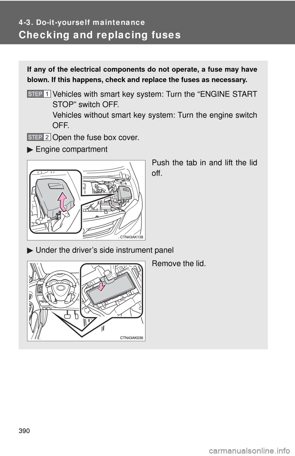
Open the fuse box cover.
Engine compartment
Push the tab in and lift the lid
off.
Under the driver’s side instrument panel Remove the lid.STEP 1
STEP 2
Page 392 of 529
391
4-3. Do-it-yourself maintenance
4
Maintenance and care
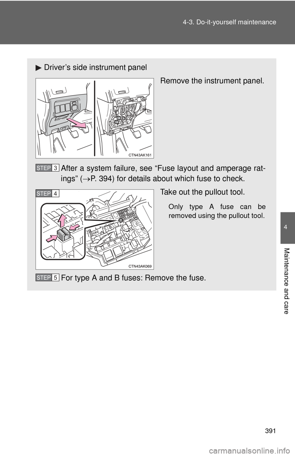
Driver’s side instrument panel
Remove the instrument panel.
After a system failure, see “Fuse layout and amperage rat-
ings” ( P. 394) for details about which fuse to check.
Take out the pullout tool.
Only type A fuse can be
removed using the pullout tool.
For type A and B fuses: Remove the fuse.
STEP 3
STEP 4
STEP 5
Page 393 of 529
392 4-3. Do-it-yourself maintenance
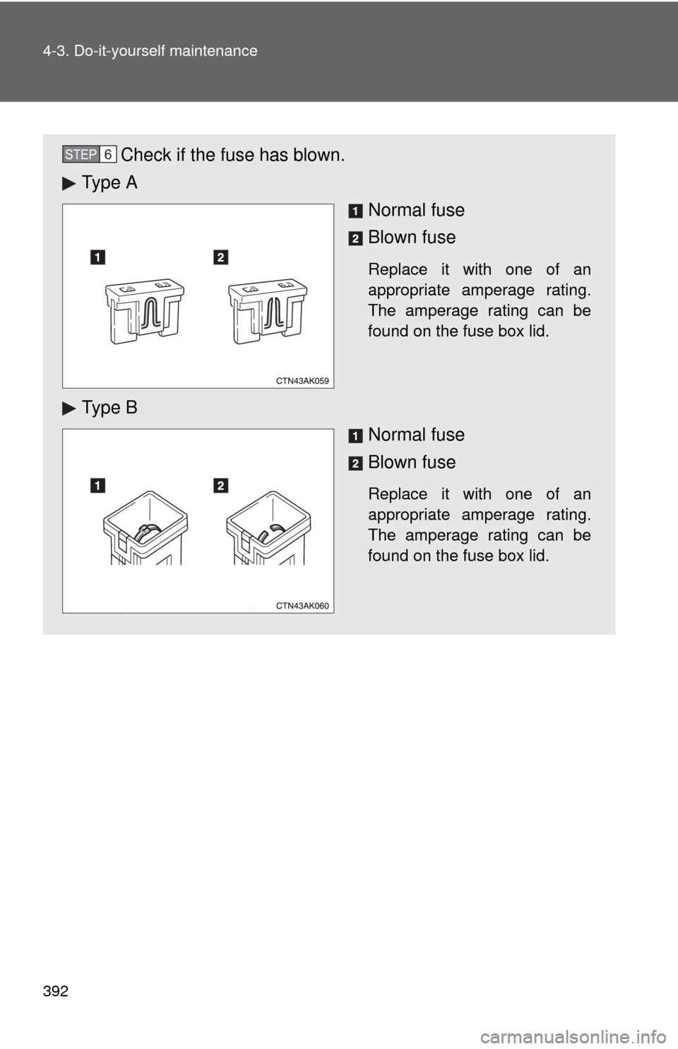
Check if the fuse has blown.
Ty p e A
Normal fuse
Blown fuse
Replace it with one of an
appropriate amperage rating.
The amperage rating can be
found on the fuse box lid.
Ty p e BNormal fuse
Blown fuse
Replace it with one of an
appropriate amperage rating.
The amperage rating can be
found on the fuse box lid.
STEP 6
Page 394 of 529
393
4-3. Do-it-yourself maintenance
4
Maintenance and care
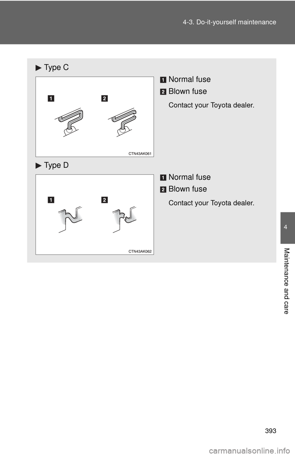
Ty p e C
Normal fuse
Blown fuse
Contact your Toyota dealer.
Ty p e D
Normal fuse
Blown fuse
Contact your Toyota dealer.
Page 395 of 529
394 4-3. Do-it-yourself maintenance
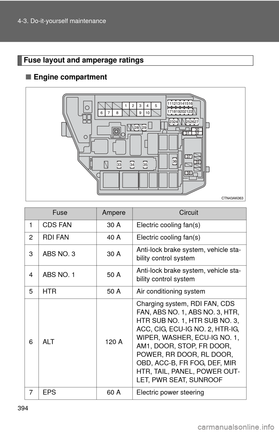
Fuse layout and amperage ratings■ Engine compartment
FuseAmpereCircuit
1 CDS FAN 30 A Electric cooling fan(s)
2 RDI FAN 40 A Electric cooling fan(s)
3 ABS NO. 3 30 A Anti-lock brake system, vehicle sta-
bility control system
4 ABS NO. 1 50 A Anti-lock brake system, vehicle sta-
bility control system
5 HTR 50 A Air conditioning system
6 ALT 120 A Charging system, RDI FAN, CDS
FAN, ABS NO. 1, ABS NO. 3, HTR,
HTR SUB NO. 1, HTR SUB NO. 3,
ACC, CIG, ECU-IG NO. 2, HTR-IG,
WIPER, WASHER, ECU-IG NO. 1,
AM1, DOOR, STOP, FR DOOR,
POWER, RR DOOR, RL DOOR,
OBD, ACC-B, FR FOG, DEF, MIR
HTR, TAIL, PANEL, POWER OUT-
LET, PWR SEAT, SUNROOF
7 EPS 60 A Electric power steering
Page 396 of 529
395
4-3. Do-it-yourself maintenance
4
Maintenance and care
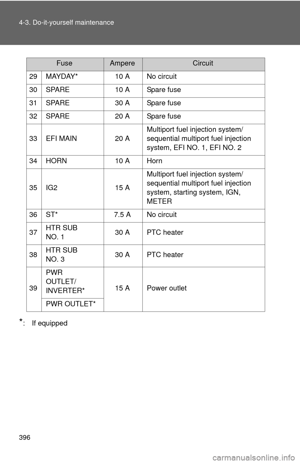
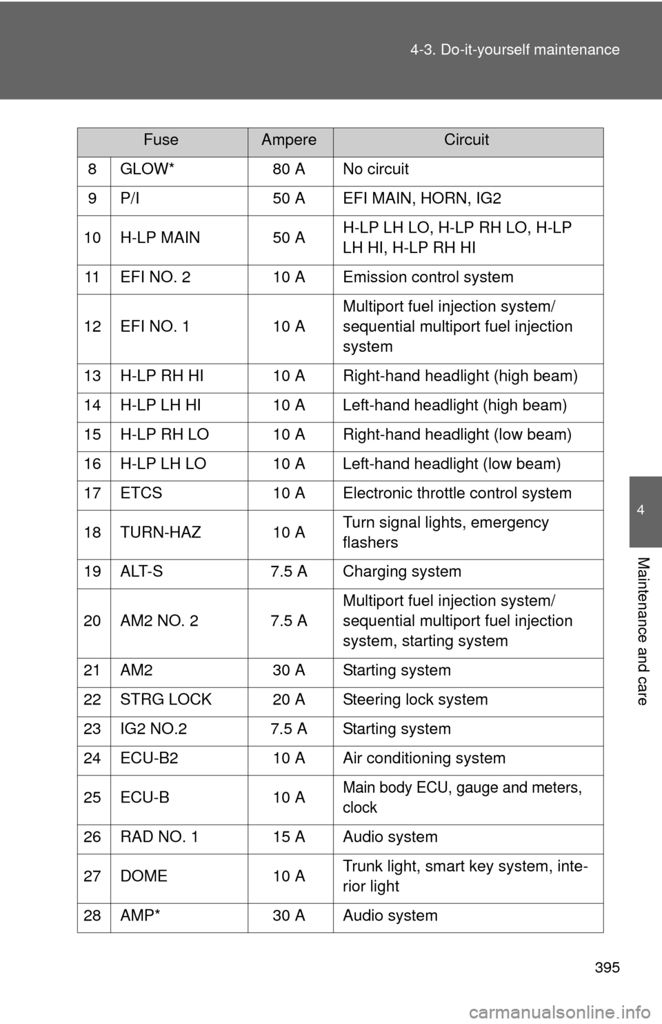
8 GLOW*
80 A No circuit
9 P/I 50 A EFI MAIN, HORN, IG2
10 H-LP MAIN 50 A H-LP LH LO, H-LP RH LO, H-LP
LH HI, H-LP RH HI
11 EFI NO. 2 10 A Emission control system
12 EFI NO. 1 10 AMultiport fuel injection system/
sequential multiport fuel injection
system
13 H-LP RH HI 10 A Right-hand headlight (high beam)
14 H-LP LH HI 10 A Left-hand headlight (high beam)
15 H-LP RH LO 10 A Right-hand headlight (low beam)
16 H-LP LH LO 10 A Left-hand headlight (low beam)
17 ETCS 10 A Electronic throttle control system
18 TURN-HAZ 10 A Turn signal lights, emergency
flashers
19 ALT-S 7.5 A Charging system
20 AM2 NO. 2 7.5 A Multiport fuel injection system/
sequential multiport fuel injection
system, starting system
21 AM2 30 A Starting system
22 STRG LOCK 20 A Steering lock system
23 IG2 NO.2 7.5 A Starting system
24 ECU-B2 10 A Air conditioning system
25 ECU-B 10 A
Main body ECU, gauge and meters,
clock
26 RAD NO. 1 15 A Audio system
27 DOME 10 A Trunk light, smart key system, inte-
rior light
28 AMP* 30 A Audio system
FuseAmpereCircuit
Page 397 of 529
396 4-3. Do-it-yourself maintenance
*: If equipped29 MAYDAY* 10 A No circuit
30 SPARE 10 A Spare fuse
31 SPARE 30 A Spare fuse
32 SPARE 20 A Spare fuse
33 EFI MAIN 20 A
Multiport fuel injection system/
sequential multiport fuel injection
system, EFI NO. 1, EFI NO. 2
34 HORN 10 A Horn
35 IG2 15 A Multiport fuel injection system/
sequential multiport fuel injection
system, starting system, IGN,
METER
36 ST* 7.5 A No circuit
37 HTR SUB
NO. 1 30 A PTC heater
38 HTR SUB
NO. 3 30 A PTC heater
39 PWR
OUTLET/
INVERTER*
15 A Power outlet
PWR OUTLET*
FuseAmpereCircuit
Page 398 of 529
397
4-3. Do-it-yourself maintenance
4
Maintenance and care
■
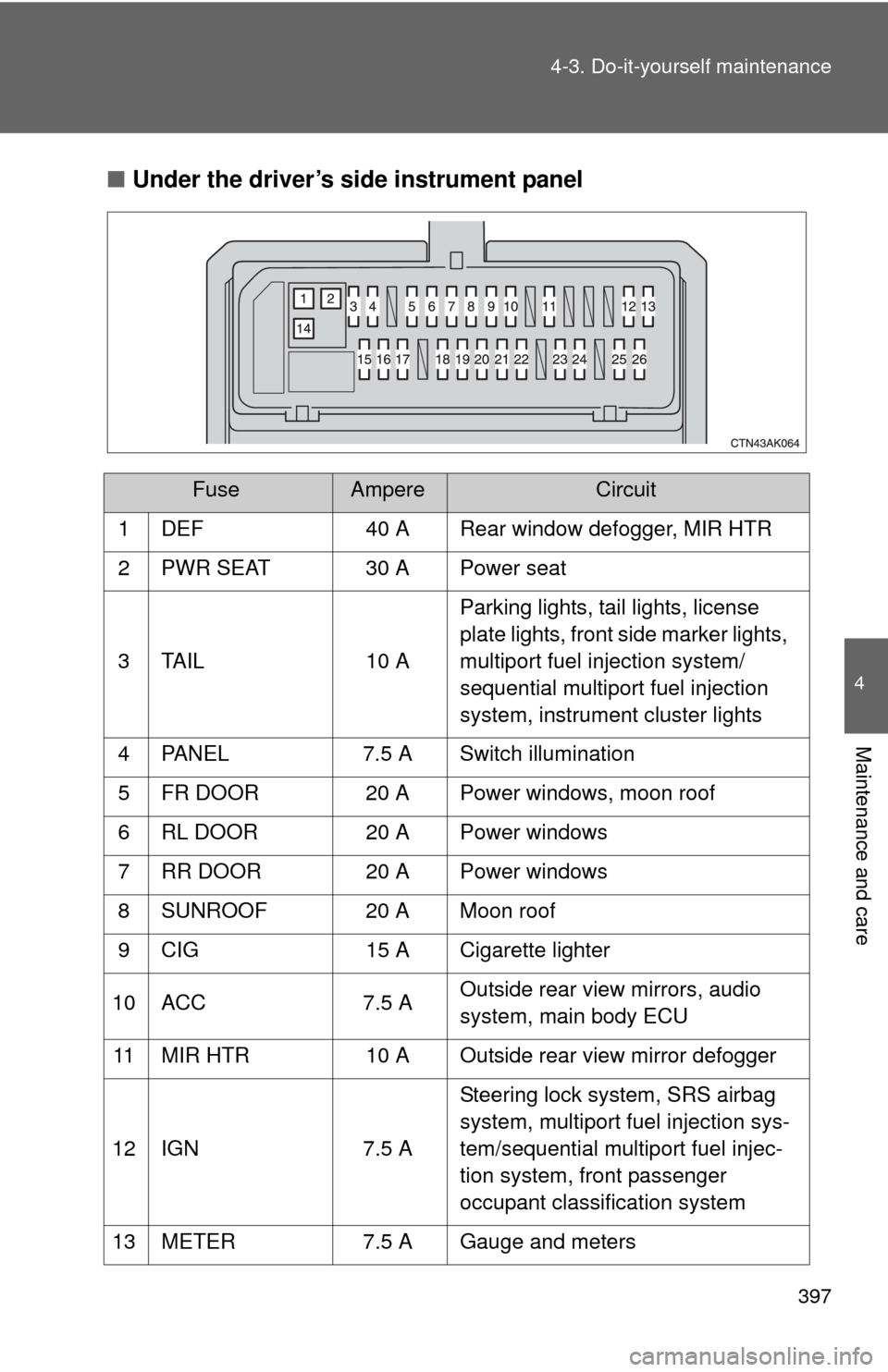
Under the driver’s side instrument panel
FuseAmpereCircuit
1 DEF 40 A Rear window defogger, MIR HTR
2 PWR SEAT 30 A Power seat
3 TAIL 10 A Parking lights, tail lights, license
plate lights, front side marker lights,
multiport fuel injection system/
sequential multiport fuel injection
system, instrument cluster lights
4 PANEL 7.5 A Switch illumination
5 FR DOOR 20 A Power windows, moon roof
6 RL DOOR 20 A Power windows
7 RR DOOR 20 A Power windows
8 SUNROOF 20 A Moon roof
9 CIG 15 A Cigarette lighter
10 ACC 7.5 A Outside rear view mirrors, audio
system, main body ECU
11 MIR HTR 10 A Outside rear view mirror defogger
12 IGN 7.5 A Steering lock system, SRS airbag
system, multiport fuel injection sys-
tem/sequential multiport fuel injec-
tion system, front passenger
occupant classification system
13 METER 7.5 A Gauge and meters
Page 399 of 529
398 4-3. Do-it-yourself maintenance
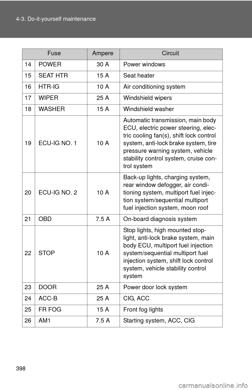
14 POWER30 A Power windows
15 SEAT HTR 15 A Seat heater
16 HTR-IG 10 A Air conditioning system
17 WIPER 25 A Windshield wipers
18 WASHER 15 A Windshield washer
19 ECU-IG NO. 1 10 A Automatic transmission, main body
ECU, electric power steering, elec-
tric cooling fan(s), shift lock control
system, anti-lock brake system, tire
pressure warning system, vehicle
stability control system, cruise con-
trol system
20 ECU-IG NO. 2 10 A Back-up lights, charging system,
rear window defogger, air condi-
tioning system, multiport fuel injec-
tion system/sequential multiport
fuel injection system, moon roof
21 OBD 7.5 A On-board diagnosis system
22 STOP 10 AStop lights, high mounted stop-
light, anti-lock brake system, main
body ECU, multiport fuel injection
system/sequential multiport fuel
injection system, shift lock control
system, vehicle stability control
system
23 DOOR 25 A Power door lock system
24 ACC-B 25 A CIG, ACC
25 FR FOG 15 A Front fog lights
26 AM1 7.5 A Starting system, ACC, CIG
FuseAmpereCircuit
Page 400 of 529
399
4-3. Do-it-yourself maintenance
4
Maintenance and care
■
After a fuse is replaced
●If the lights do not turn on even after the fuse has been replaced, a bulb
may need replacing. ( P. 400)
● If the replaced fuse blows again, have the vehicle inspected by your
Toyota dealer.
■ If there is an overload in the circuits
The fuses are designed to blow, protecting the wiring harness from damage.
CAUTION
■To prevent system breakdowns and vehicle fire
Observe the following precautions.
Failing to do so may cause damage, and possibly a fire or injury.
●Never use a fuse of a higher amperage rating than indicated, or use any
other object in place of a fuse.
● Always use a genuine Toyota fuse or equivalent.
Never replace a fuse with a wire, even as a temporary fix.
This can cause extensive damage or even fire.
● Do not modify the fuse or the fuse box.
NOTICE
■Before replacing fuses
Have the cause of electrical overload determined and repaired by your
Toyota dealer, as soon as possible.
Trending: tire size, lock, air filter, hood release, lumbar support, trunk, high beam
