key TOYOTA COROLLA 2012 10.G Repair Manual
[x] Cancel search | Manufacturer: TOYOTA, Model Year: 2012, Model line: COROLLA, Model: TOYOTA COROLLA 2012 10.GPages: 529, PDF Size: 8.07 MB
Page 325 of 529
325
3-7. Other interior features
3
Interior features
Power outlet
■The power outlet can be used when
Vehicles with smart key system
The “ENGINE START STOP” switch is in ACCESSORY or IGNITION ON
mode. Vehicles without smart key system
The engine switch is in the “ACC” or “ON” position.
NOTICE
■ To avoid damaging the power outlet
Close the power outlet lid when the power outlet is not in use.
Foreign objects or liquids that enter the power outlet may cause a short cir-
cuit.
■ To prevent the fuse from being blown
Do not use an accessory that uses more than 12 V 10 A.
■ To prevent the battery from being discharged
Do not use the power outlet longer than necessary when the engine is not\
running.
: If equipped
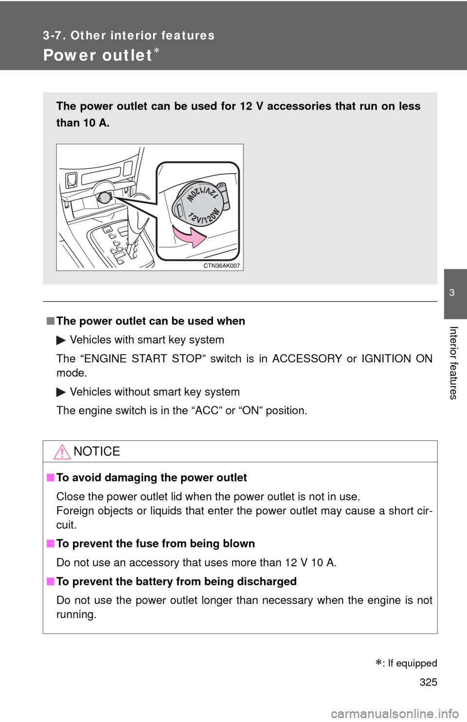
The power outlet can be used for 12 V accessories that run on less
than 10 A.
Page 326 of 529
326
3-7. Other interior features
Seat heaters
■The seat heaters can be used when
Vehicles with smart key system
The “ENGINE START STOP” switch is in IGNITION ON mode.
Vehicles without smart key system
The engine switch is in the “ON” position.
CAUTION
■ Burns
●Use caution when seating the following persons in a seat with the seat
heater on to avoid the possibility of burns:
• Babies, small children, the elderly, the sick and the disabled
• Persons with sensitive skin
• Persons who are fatigued
• Persons who have taken alcohol or drugs that induce sleep (sleeping
drugs, cold remedies, etc.)
● Do not cover the seat with anything when using the seat heater.
Using the seat heater with a blanket or cushion increases the temperature
of the seat and may lead to overheating.
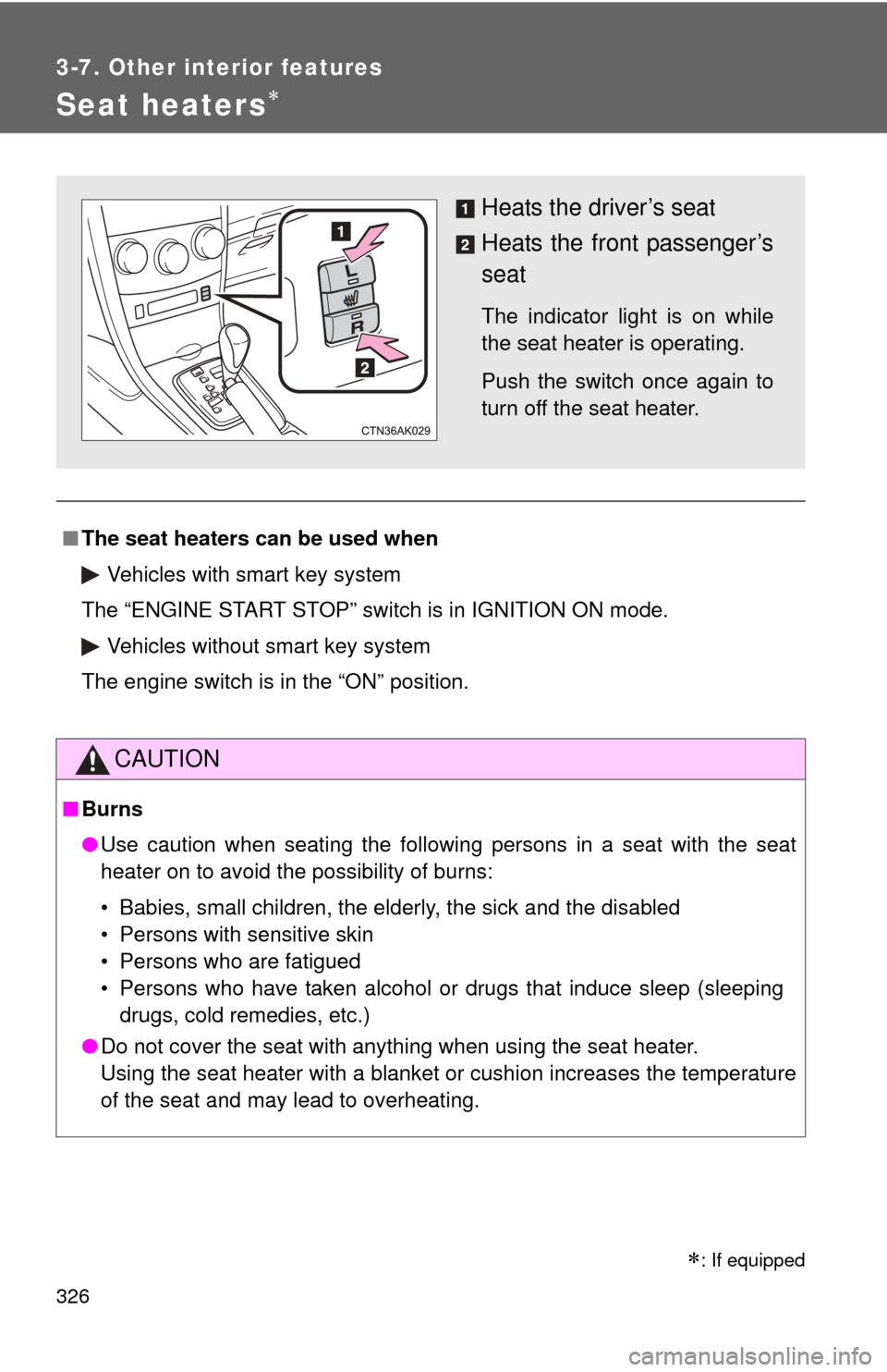
Heats the driver’s seat
Heats the front passenger’s
seat
The indicator light is on while
the seat heater is operating.
Push the switch once again to
turn off the seat heater.
: If equipped
Page 333 of 529
Maintenance and care4
333
4-1. Maintenance and careCleaning and protecting the vehicle exterior......... 334
Cleaning and protecting the vehicle interior.......... 336
4-2. Maintenance Maintenance requirements .................. 339
General maintenance....... 341
Emission inspection and maintenance (I/M)
programs........................ 344 4-3. Do-it-yourself
maintenance
Do-it-yourself service precautions .................... 345
Hood ................................ 349
Positioning a floor jack ..... 351
Engine compartment ........ 354
Tires ................................. 368
Tire inflation pressure ...... 376
Wheels ............................. 380
Air conditioning filter......... 383
Key battery ....................... 385
Checking and replacing fuses .............................. 389
Light bulbs........................ 399
Page 347 of 529

347
4-3. Do-it-yourself maintenance
4
Maintenance and care
CAUTION
The engine compartment contains many mechanisms and fluids that may
move suddenly, become hot, or become electrically energized. To avoid death
or serious injury observe the following precautions.
■
When working on the engine compartment
●Keep hands, clothing, and tools away from the moving fan and engine
drive belt.
● Be careful not to touch the engine, radiator, exhaust manifold, etc. right
after driving as they may be hot. Oil and other fluids may also be hot.
● Do not leave anything that may burn easily, such as paper or rags, in the
engine compartment.
● Do not smoke, cause sparks or expose an open flame to fuel or the bat-
tery. Fuel and battery fumes are flammable.
● Be extremely cautious when working on the battery. It contains poisonous
and corrosive sulfuric acid.
● Take care because brake fluid can harm your hands or eyes and damage
painted surfaces.
If fluid gets on your hands or in your eyes, flush the affected area with
clean water immediately.
If you still experience discomfort, see a doctor.
■ When working near the electric c ooling fans or radiator grille
Vehicles with smart key system: Be sure the “ENGINE START STOP” switch
is OFF. With the “ENGINE START STOP” switch in IGNITION ON mode, the
electric cooling fans may automatically start to run if the air conditioning is on
and/or the coolant temperature is high. ( P. 361)
Vehicles without smart key system: Be sure the engine switch is OFF. With
the engine switch in the “ON” position, the electric cooling fans may auto-
matically start to run if the air conditioning is on and/or the coolant tempera-
ture is high. ( P. 361)
■ Safety glasses
Wear safety glasses to prevent flying or falling material, fluid spray, etc. from
getting in the eyes.
Page 364 of 529
364 4-3. Do-it-yourself maintenance
BatteryCheck the battery as follows.
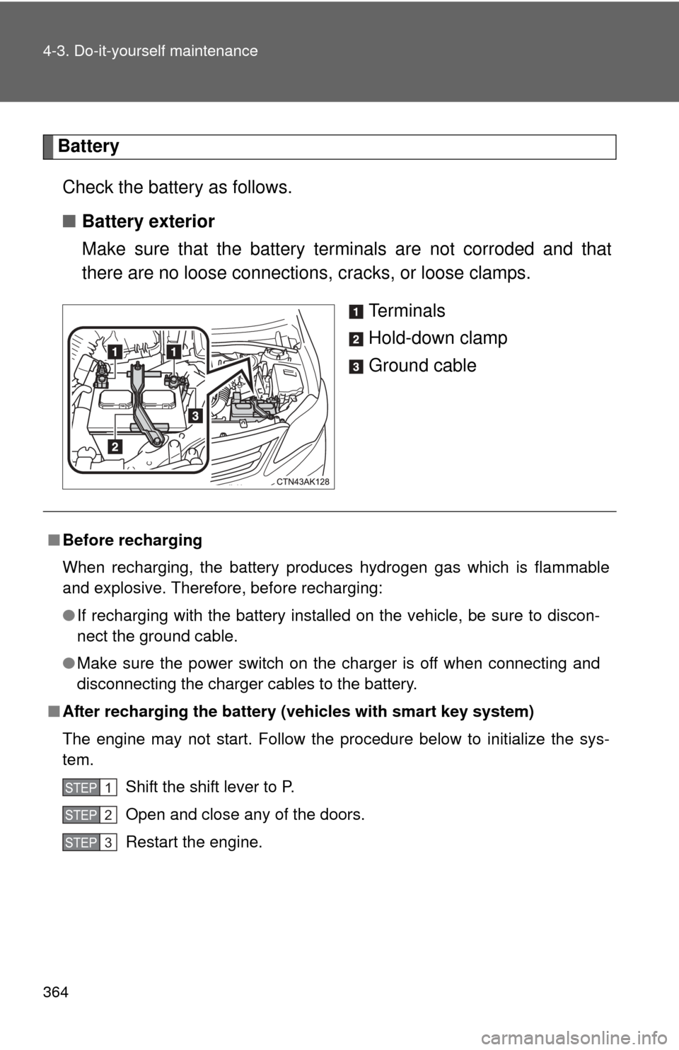
■ Battery exterior
Make sure that the battery terminals are not corroded and that
there are no loose connections, cracks, or loose clamps.
Te r m i n a l s
Hold-down clamp
Ground cable
■Before recharging
When recharging, the battery produces hydrogen gas which is flammable
and explosive. Therefore, before recharging:
●If recharging with the battery installed on the vehicle, be sure to discon-
nect the ground cable.
● Make sure the power switch on the charger is off when connecting and
disconnecting the charger cables to the battery.
■ After recharging the battery (vehicles with smart key system)
The engine may not start. Follow the procedure below to initialize the sys-
tem.
Shift the shift lever to P.
Open and close any of the doors.
Restart the engine.
STEP 1
STEP 2
STEP 3
Page 369 of 529

369
4-3. Do-it-yourself maintenance
4
Maintenance and care
Installing tire pressure warning valves and transmitters
When replacing tires or wheels, tire pressure warning valves and
transmitters must also be installed.
When new tire pressure warning valves and transmitters are
installed, new tire pressure warning valve and transmitter ID codes
must be registered in the tire pre ssure warning computer and the tire
pressure warning system must be initialized. Have tire pressure
warning valve and transmitter ID codes registered by your Toyota
dealer. ( P. 370)
Initializing the tire pressure warning system
The tire pressure warning system must be initialized when changing
the tire size.
When the tire pressure warning syst em is initialized, the current tire
inflation pressure is set as the pressure benchmark.
■ How to initialize the tire pressure warning system
Park the vehicle in a safe place and turn the “ENGINE START
STOP” switch or the engine switch OFF.
While the vehicle is moving, in itialization is not performed.
Adjust the tire inflation pressure to the specified cold tire infla-
tion pressure level. ( P. 474)
Make sure to adjust the tire pressure to the specified cold tire
inflation pressure level. The ti re pressure warning system will
operate based on this pressure level.
Turn the “ENGINE START STOP” switch to IGNITION ON
mode (vehicles with smart key sy stem) or the engine switch to
the “ON” position (vehicles without smart key system).
STEP 1
STEP 2
STEP 3
Page 370 of 529
370 4-3. Do-it-yourself maintenance
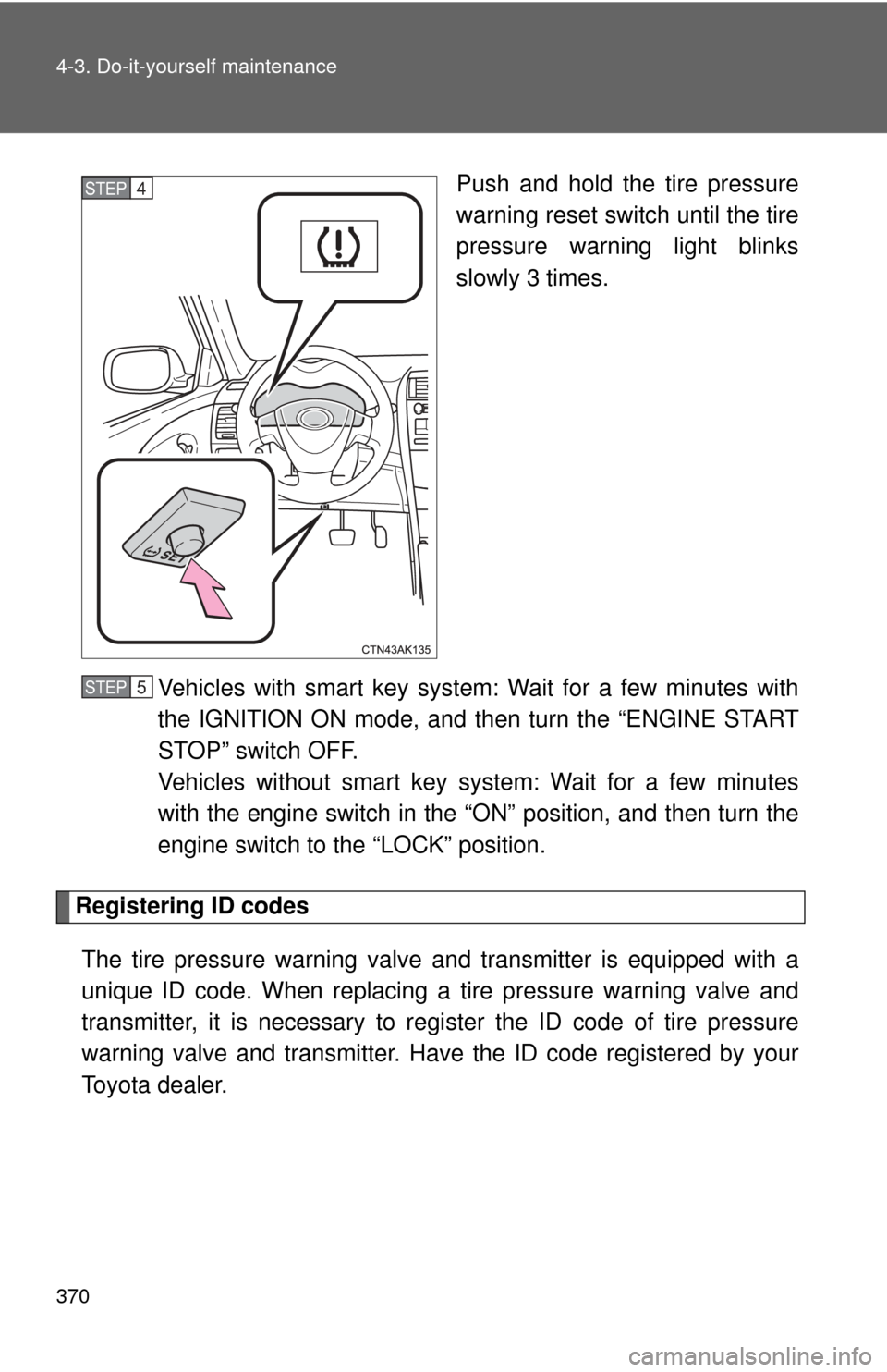
Push and hold the tire pressure
warning reset switch until the tire
pressure warning light blinks
slowly 3 times.
Vehicles with smart key system: Wait for a few minutes with
the IGNITION ON mode, and then turn the “ENGINE START
STOP” switch OFF.
Vehicles without smart key system: Wait for a few minutes
with the engine switch in the “O N” position, and then turn the
engine switch to the “LOCK” position.
Registering ID codes
The tire pressure warning valve and transmitter is equipped with a
unique ID code. When replacing a tire pressure warning valve and
transmitter, it is necessary to regi ster the ID code of tire pressure
warning valve and transmitter. Have the ID code registered by your
Toyota dealer.
STEP 4
STEP 5
Page 383 of 529
383
4-3. Do-it-yourself maintenance
4
Maintenance and care
Air conditioning filter
The air conditioning filter must be changed regularly to maintain air
conditioning efficiency.
■ Removal method
Vehicles with smart key system: Turn the “ENGINE START
STOP” switch OFF.
Vehicles without smart key system: Turn the engine switch
OFF.
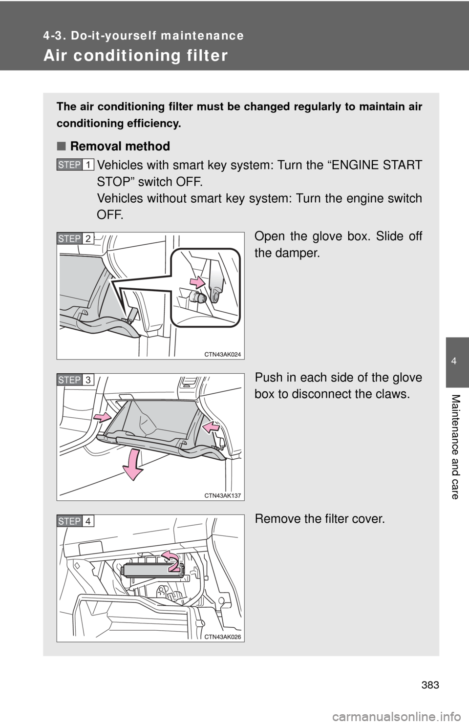
Open the glove box. Slide off
the damper.
Push in each side of the glove
box to disconnect the claws.
Remove the filter cover.
STEP 1
STEP 2
STEP 3
STEP 4
Page 385 of 529
385
4-3. Do-it-yourself maintenance
4
Maintenance and care
Key batter y
Replace the battery with a new one if it is discharged.
■You will need the following items:
●Flathead screwdriver (To prevent damage to the key, cover
the tip of the screwdriver with a rag.)
● Small Phillips-hea d screwdriver
● Lithium battery
Vehicles with smart key system: CR1632
Vehicles without smart ke y system: CR2025 (Type A)
CR2016 (Type B)
■ Replacing the battery (vehicles with smart key system)
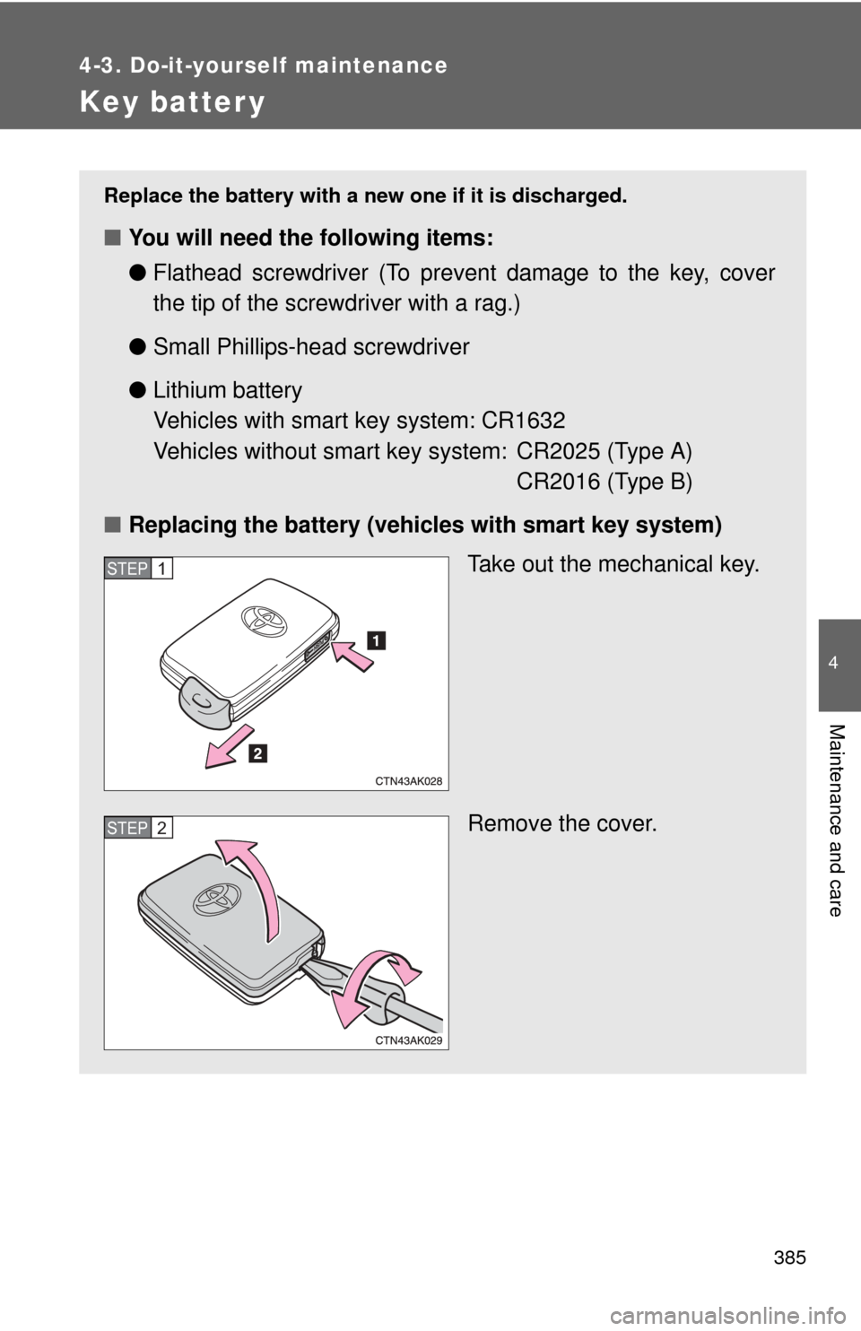
Take out the mechanical key.
Remove the cover.
STEP 1
STEP 2
Page 386 of 529
386 4-3. Do-it-yourself maintenance
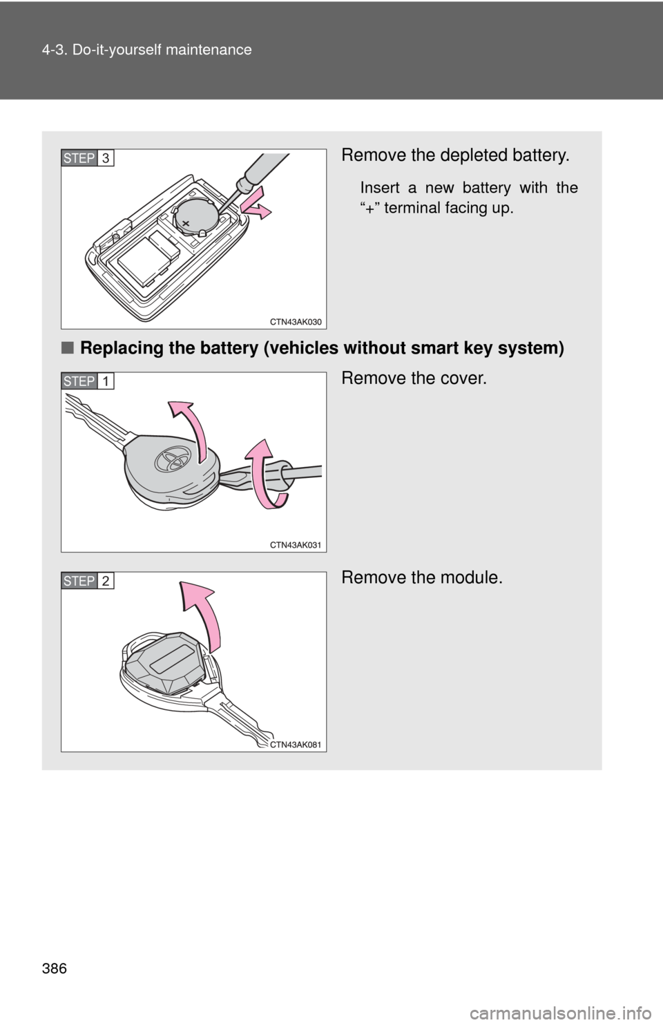
Remove the depleted battery.
Insert a new battery with the
“+” terminal facing up.
■Replacing the battery (vehicles without smart key system)
Remove the cover.
Remove the module.
STEP 3
STEP 1
STEP 2