ABS TOYOTA COROLLA 2022 Owners Manual (in English)
[x] Cancel search | Manufacturer: TOYOTA, Model Year: 2022, Model line: COROLLA, Model: TOYOTA COROLLA 2022Pages: 678, PDF Size: 147.24 MB
Page 76 of 678
741-4. Theft deterrent system
1-4.Theft deterrent system
Vehicles without a smart entry &
start system
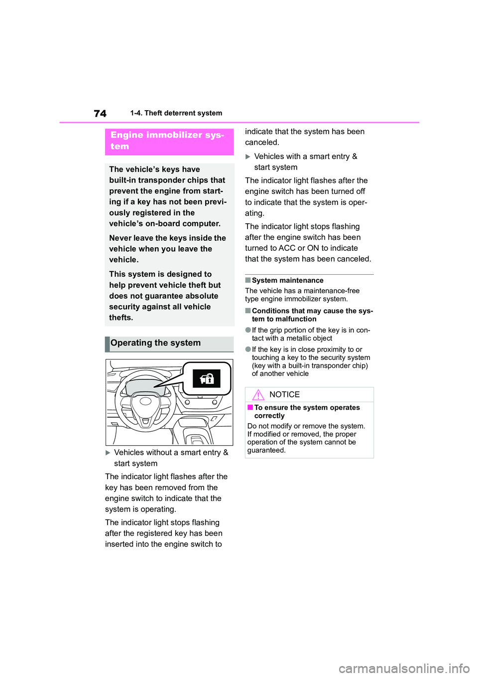
The indicator light flashes after the
key has been removed from the
engine switch to indicate that the
system is operating.
The indicator light stops flashing
after the registered key has been
inserted into the engine switch to
indicate that the system has been
canceled.
Vehicles with a smart entry &
start system
The indicator light flashes after the
engine switch has been turned off
to indicate that the system is oper-
ating.
The indicator light stops flashing
after the engine switch has been
turned to ACC or ON to indicate
that the system has been canceled.
■System maintenance
The vehicle has a maintenance-free
type engine immobilizer system.
■Conditions that may cause the sys-
tem to malfunction
●If the grip portion of the key is in con-
tact with a metallic object
●If the key is in close proximity to or
touching a key to the security system (key with a built-in transponder chip)
of another vehicle
Engine immobilizer sys-
tem
The vehicle’s keys have
built-in transponder chips that
prevent the engine from start-
ing if a key has not been previ-
ously registered in the
vehicle’s on-board computer.
Never leave the keys inside the
vehicle when you leave the
vehicle.
This system is designed to
help prevent vehicle theft but
does not guarantee absolute
security against all vehicle
thefts.
Operating the system
NOTICE
■To ensure the system operates
correctly
Do not modify or remove the system.
If modified or removed, the proper
operation of the system cannot be guaranteed.
Page 84 of 678
822-1. Instrument cluster
*1: These lights come on when the
engine switch is turned to ON to indi-
cate that a system check is being
performed. They will turn off after the
engine is started, or after a few sec-
onds. There may be a malfunction in
a system if the lights do not come
on, or turn off. Have the vehicle
inspected by any authorized Toyota
retailer or Toyota authorized repairer,
or any reliable repairer.
*2: As these lights are displayed on the
multi-information display, they will
not turn on when a system check, as
described in*1 above, is being per-
formed.
*3: This light illuminates on the
multi-information display.
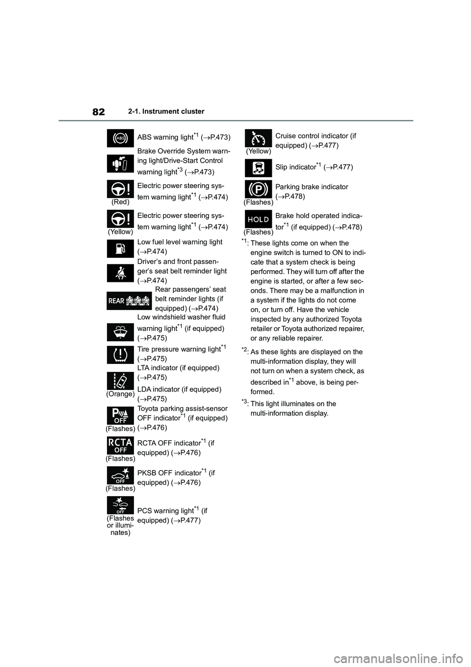
ABS warning light*1 ( P.473)
Brake Override System warn-
ing light/Drive-S tart Control
warning light*3 ( P.473)
(Red)
Electric power steering sys-
tem warning light*1 ( P.474)
(Yellow)
Electric power steering sys-
tem warning light*1 ( P.474)
Low fuel level warning light
( P.474)
Driver’s and front passen-
ger’s seat belt reminder light
( P.474)
Rear passengers’ seat
belt reminder lights (if
equipped) ( P.474)
Low windshield washer fluid
warning light*1 (if equipped)
( P.475)
Tire pressure warning light*1
( P.475)
(Orange)
LTA indicator (if equipped)
( P.475)
LDA indicator (if equipped)
( P.475)
(Flashes)
Toyota parking assist-sensor
OFF indicator*1 (if equipped)
( P.476)
(Flashes)
RCTA OFF indicator*1 (if
equipped) ( P.476)
(Flashes)
PKSB OFF indicator*1 (if
equipped) ( P.476)
(Flashes or illumi-nates)
PCS warning light*1 (if
equipped) ( P.477)
(Yellow)
Cruise control indicator (if
equipped) ( P.477)
Slip indicator*1 ( P.477)
(Flashes)
Parking brake indicator
( P.478)
(Flashes)
Brake hold operated indica-
tor*1 (if equipped) ( P.478)
Page 85 of 678
83
2
2-1. Instrument cluster
Vehicle status information and indicators
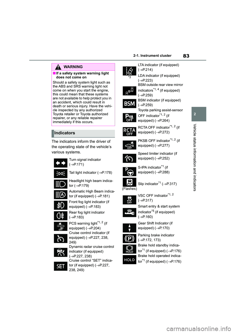
The indicators inform the driver of
the operating state of the vehicle’s
various systems.
WA R N I N G
■If a safety system warning light
does not come on
Should a safety system light such as the ABS and SRS warning light not
come on when you start the engine,
this could mean that these systems are not available to help protect you in
an accident, which could result in
death or serious injury. Have the vehi-
cle inspected by any authorized Toyota retailer or Toyota authorized
repairer, or any reliable repairer
immediately if this occurs.
Indicators
Turn signal indicator
( P.171)
Tail light indicator ( P.178)
Headlight high beam indica-
tor ( P.179)
Automatic High Beam indica-
tor (if equipped) ( P.181)
Front fog light indicator (if
equipped) ( P.183)
Rear fog light indicator
( P.183)
PCS warning light*1, 2 (if
equipped) ( P.204)
Cruise control indicator (if
equipped) ( P.227, 238,
249)
Dynamic radar cruise control
indicator (if equipped)
( P.227, 238)
Cruise control “SET” indica-
tor (if equipped) ( P.227,
238, 249)
*3
LTA indicator (if equipped)
( P.214)
LDA indicator (if equipped)
( P.223)
BSM outside rear view mirror
indicators*1, 4 (if equipped)
( P.259)
BSM indicator (if equipped)
( P.259)
Toyota parking assist-sensor
OFF indicator*1, 2 (if
equipped) ( P.264)
RCTA OFF indicator*1, 2 (if
equipped) ( P.272)
PKSB OFF indicator*1, 2 (if
equipped) ( P.277)
Speed limiter indicator (if
equipped) ( P.252)
S-IPA indicator*1 (if
equipped) ( P.288)
(Flashes)
Slip indicator*1 ( P.317)
VSC OFF indicator*1, 2
( P.317)
Smart entry & start system
indicator*5 (if equipped)
( P.160)
Gear Shift Indicator (if
equipped) ( P.170)
Parking brake indicator
( P.172, 173)
Brake hold standby indica-
tor*1 (if equipped) ( P.176)
Brake hold operated indica-
tor*1 (if equipped) ( P.176)
Page 218 of 678
2164-5. Using the driving support systems
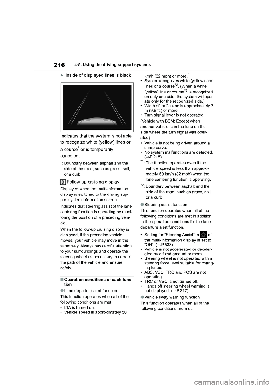
Inside of displayed lines is black
Indicates that the system is not able
to recognize white (yellow) lines or
a course* or is temporarily
canceled.
*: Boundary between asphalt and the
side of the road, such as grass, soil,
or a curb
Follow-up cruising display
Displayed when the multi-information
display is switched to the driving sup-
port system info rmation screen.
Indicates that steering assist of the lane
centering function is operating by moni-
toring the position of a preceding vehi-
cle.
When the follow-up cruising display is
displayed, if the preceding vehicle
moves, your vehicle may move in the
same way. Always pay careful attention
to your surroundings and operate the
steering wheel as necessary to correct
the path of the vehicle and ensure
safety.
■Operation conditions of each func- tion
●Lane departure alert function
This function operates when all of the
following conditions are met.
• LTA is turned on.
• Vehicle speed is approximately 50
km/h (32 mph) or more.*1
• System recognizes white (yellow) lane
lines or a course*2. (When a white
[yellow] line or course*2 is recognized
on only one side, the system will oper- ate only for the recognized side.)
• Width of traffic lane is approximately 3
m (9.8 ft.) or more. • Turn signal lever is not operated.
(Vehicle with BSM: Except when
another vehicle is in the lane on the
side where the turn signal was oper-
ated)
• Vehicle is not being driven around a
sharp curve. • No system malfunctio ns are detected.
( P.218)*1: The function operates even if the
vehicle speed is less than approxi-
mately 50 km/h (32 mph) when the
lane centering function is operating.
*2: Boundary between asphalt and the
side of the road, such as grass, soil,
or a curb
●Steering assist function
This function operates when all of the
following conditions are met in addition
to the operation conditions for the lane
departure alert function.
• Setting for “Steering Assist” in of
the multi-information display is set to “ON”. ( P.538)
• Vehicle is not accelerated or deceler-
ated by a fixed amount or more. • Steering wheel is not operated with a
steering force level suitable for chang-
ing lanes.
• ABS, VSC, TRC and PCS are not operating.
• TRC or VSC is not turned off.
• Hands off steering wheel warning is not displayed. ( P.217)
●Vehicle sway warning function
This function operates when all of the
following conditions are met.
Page 219 of 678
217
4
4-5. Using the driving support systems
Driving
• Setting for “Sway Warning” in of
the multi-information display is set to “ON”. ( P.538)
• Vehicle speed is approximately 50
km/h (32 mph) or more. • Width of traffic lane is approximately 3
m (9.8 ft.) or more.
• No system malfunctions are detected. ( P.218)
●Lane centering function
This function operates when all of the
following conditions are met.
• LTA is turned on.
• Setting for “Steering Assist” and “Lane
Centre” in of th e multi-information
display are set to “ON” ( P.538)
• This function recognizes white (yel-
low) lane lines or the position of a preceding vehicle (except when the
preceding vehicle is small, such as a
motorcycle). • The dynamic radar cruise control with
full-speed range is operating in vehi-
cle-to-vehicle distance control mode. • Width of traffic lane is approximately 3
to 4 m (10 to 13 ft.).
• Turn signal lever is not operated. • Vehicle is not being driven around a
sharp curve.
• No system malfunctions are detected. ( P.218)
• Vehicle does not accelerate or
decelerate by a fixed amount or more. • Steering wheel is not operated with a
steering force level suitable for chang-
ing lanes.
• ABS, VSC, TRC and PCS are not operating.
• TRC or VSC is not turned off.
• Hands off steering wheel warning is not displayed. ( P.217)
• The vehicle is being driven in the
center of a lane. • Steering assist function is not operat-
ing.
■Temporary cancellation of func-
tions
●When operation conditions are no
longer met, a function may be tempo-
rarily canceled. However, when the
operation conditions are met again, operation of the function is automati-
cally restored. ( P.216)
●If the operation conditions (P.216)
are no longer met while the lane cen-
tering function is operating, the buzzer may sound to indicate that the func-
tion has been temporarily canceled.
■Steering assist function/lane cen-
tering function
●Depending on the vehicle speed, lane
departure situation, road conditions, etc., the driver may not feel the func-
tion is operating or the function may
not operate at all.
●The steering control of the function is
overridden by the driver’s steering wheel operation.
●Do not attempt to test the operation of the steering assist function.
■Lane departure alert function
●The warning buzzer may be difficult to hear due to external noise, audio play-
back, etc.
●If the edge of the course* is not clear
or straight, the lane departure alert
function may not operate.
●Vehicle with BSM: It may not be possi-
ble for the system to determine if there is a danger of a collision with a vehicle
in an adjacent lane.
●Do not attempt to test the operation of
the lane departure alert function.*: Boundary between asphalt and the
side of the road, such as grass, soil,
or a curb
■Hands off steering wheel warning
In the following situations, a warning message urging the driver to hold the
steering wheel and the symbol shown in
the illustration are displayed on the multi-information display to warn the
driver. The warning stops when the sys-
tem determines that the driver holds the steering wheel. Always keep your hands
Page 226 of 678
2244-5. Using the driving support systems
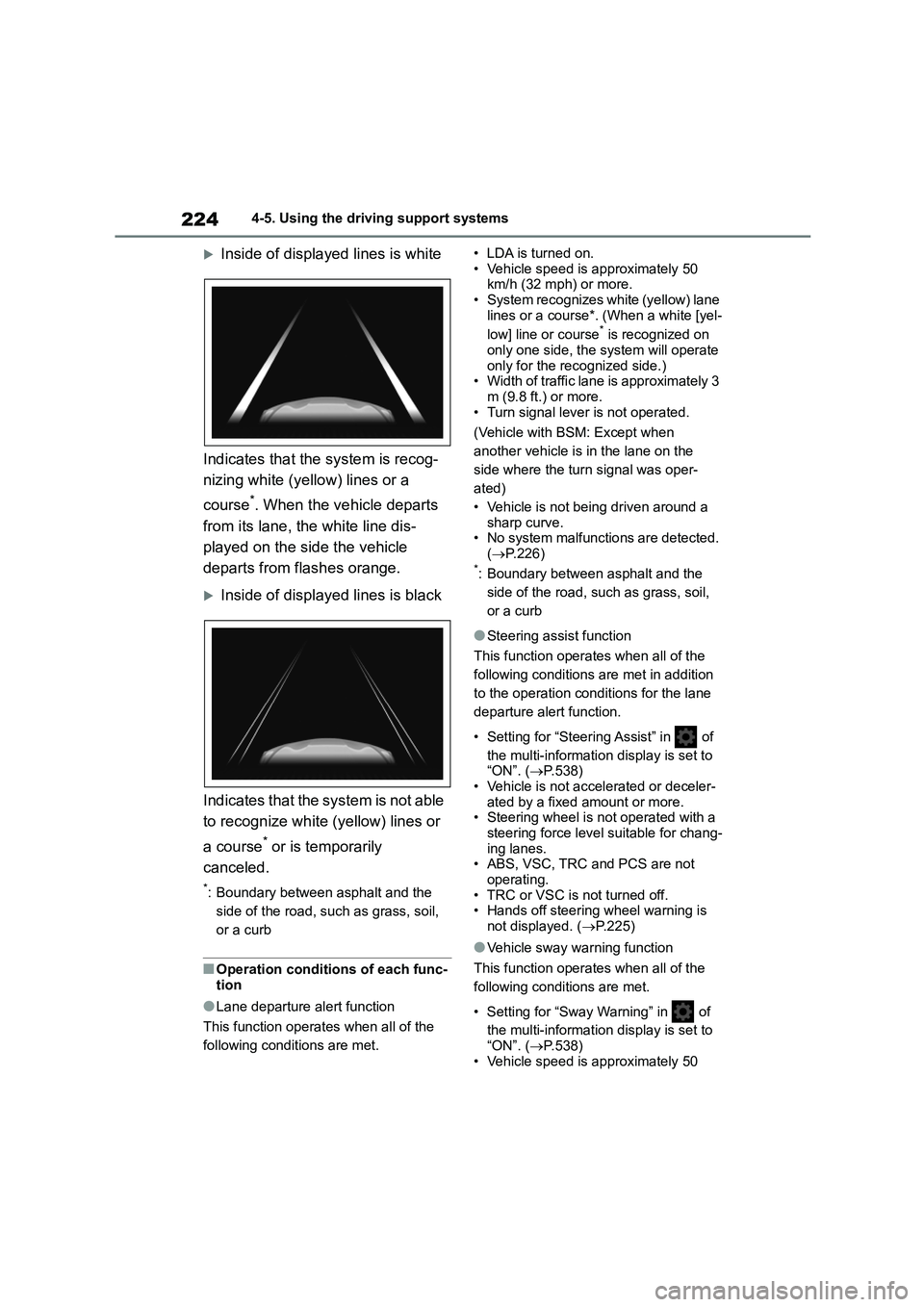
Inside of displayed lines is white
Indicates that the system is recog-
nizing white (yellow) lines or a
course*. When the vehicle departs
from its lane, the white line dis-
played on the side the vehicle
departs from flashes orange.
Inside of displayed lines is black
Indicates that the system is not able
to recognize white (yellow) lines or
a course* or is temporarily
canceled.
*: Boundary between asphalt and the
side of the road, such as grass, soil,
or a curb
■Operation conditions of each func-
tion
●Lane departure alert function
This function operates when all of the
following conditions are met.
• LDA is turned on.
• Vehicle speed is approximately 50 km/h (32 mph) or more.
• System recognizes white (yellow) lane
lines or a course*. (When a white [yel-
low] line or course* is recognized on
only one side, the system will operate
only for the recognized side.) • Width of traffic lane is approximately 3
m (9.8 ft.) or more.
• Turn signal lever is not operated.
(Vehicle with BSM: Except when
another vehicle is in the lane on the
side where the turn signal was oper-
ated)
• Vehicle is not being driven around a
sharp curve.
• No system malfunctio ns are detected. ( P.226)*: Boundary between asphalt and the
side of the road, such as grass, soil,
or a curb
●Steering assist function
This function operates when all of the
following conditions are met in addition
to the operation conditions for the lane
departure alert function.
• Setting for “Steering Assist” in of
the multi-information display is set to
“ON”. ( P.538) • Vehicle is not accelerated or deceler-
ated by a fixed amount or more.
• Steering wheel is not operated with a steering force level suitable for chang-
ing lanes.
• ABS, VSC, TRC and PCS are not operating.
• TRC or VSC is not turned off.
• Hands off steering wheel warning is
not displayed. ( P.225)
●Vehicle sway warning function
This function operates when all of the
following conditions are met.
• Setting for “Sway Warning” in of
the multi-information display is set to
“ON”. ( P.538)
• Vehicle speed is approximately 50
Page 230 of 678
2284-5. Using the driving support systems
WA R N I N G
• Conditions under which the vehi-
cle-to-vehicle distance control
mode may not function correctly: P. 2 3 7
●Set the speed appropriately depending on the speed limit, traffic
flow, road conditions, weather con-
ditions, etc. The driver is responsi-
ble for checking the set speed.
●Even when the system is function-
ing normally, the condition of the preceding vehicle as detected by
the system may differ from the con-
dition observed by the driver. Therefore, the driver must always
remain alert, assess the danger of
each situation and drive safely. Relying solely on this system or
assuming the system ensures
safety while driving can lead to an accident, resulting in death or seri-
ous injury.
●Switch the dynamic radar cruise
control with full-speed range setting
to off, using the cruise control main switch when not in use.
■Cautions regarding the driving assist systems
Observe the following precautions, as
there are limitations to the assistance provided by the system . Failure to do
so may cause an accident resulting in
death or serious injury.
●Assisting the driver to measure fol- lowing distance
The dynamic radar cruise control with
full-speed range is only intended to help the driver in determining the fol-
lowing distance between the driver’s
own vehicle and a designated vehicle traveling ahead. It is not a mechanism
that allows careless or inattentive
driving, and it is not a system that can assist the driver in low-visibility condi-
tions.
It is still necessary for driver to pay close attention to the vehicle’s
surroundings.
●Assisting the driver to judge proper
following distance
The dynamic radar cruise control with full-speed range determines whether
the following distance between the
driver’s own vehicle and a designated vehicle traveling ahead is within a set
range. It is not capable of making any
other type of judgement. Therefore, it is absolutely necessary for the driver
to remain vigilant and to determine
whether or not there is a possibility of danger in any given situation.
●Assisting the driver to operate the vehicle
The dynamic radar cruise control with
full-speed range does not include functions which will prevent or avoid
collisions with vehicles ahead of your
vehicle. Therefore, if there is ever any possibility of danger, the driver must
take immediate and direct control of
the vehicle and act appropriately in order to ensure the safety of all
involved.
Page 242 of 678
2404-5. Using the driving support systems
WA R N I N G
●Assisting the driver to judge proper
following distance
The dynamic radar cruise control determines whether the following dis-
tance between the driver’s own vehi-
cle and a designated vehicle traveling ahead is within a set range. It is not
capable of making any other type of
judgement. Therefore, it is absolutely
necessary for the driver to remain vig- ilant and to determine whether or not
there is a possibility of danger in any
given situation.
●Assisting the driver to operate the
vehicle
The dynamic radar cruise control
does not include functions which will
prevent or avoid collisions with vehi- cles ahead of your vehicle. Therefore,
if there is ever any possibility of dan-
ger, the driver must take immediate and direct control of the vehicle and
act appropriately in order to ensure
the safety of all involved.
■Situations unsuitable for
dynamic radar cruise control
Do not use dynamic radar cruise con-
trol in any of the following situations.
Doing so may result in inappropriate speed control and could cause an
accident resulting in death or serious
injury.
●Roads where there are pedestrians,
cyclists, etc.
●In heavy traffic
●On roads with sharp bends
●On winding roads
●On slippery roads, such as those
covered with rain, ice or snow
●On steep downhills, or where there are sudden changes between sharp
up and down gradients
Vehicle speed may exceed the set speed when driving down a steep hill.
●At entrances to freeways and high-ways
●When weather conditions are bad enough that they may prevent the
sensors from detecting correctly
(fog, snow, sandstorm, heavy rain, etc.)
●When there is rain, snow, etc. on the front surface of the radar or
front camera
●In traffic conditions that require fre-
quent repeated acceleration and
deceleration
●When your vehicle is towing a
trailer or during emergency towing
●When an approach warning buzzer
is heard often
Page 268 of 678
2664-5. Using the driving support systems
■If “Parking Assist Unavailable
Please Clean Parking Assist Sen- sor” is displayed on the multi-infor-
mation display
A sensor may be covered with ice, snow, dirt, etc. Remove the ice, snow,
dirt, etc., from the sensor to return the
system to normal.
Also, due to ice forming on a sensor at
low temperatures, a warning message
may be displayed or the sensor may not be able to detect an object. Once the ice
melts, the system will return to normal.
■Sensor detection information
The following situations may occur dur- ing use.
●The sensors may be able to only detect objects near the front and rear
bumpers.
●Depending on the shape of the object
and other factors, the detection dis-
tance may shorten, or detection may be impossible.
●If an object is extremely close to a sensor, it may not be detected.
●There will be a short delay between object detection and display. Even at
low speeds, there is a possibility that
the object will come within the sen- sor’s detection areas before the dis-
play is shown and the warning beep
sounds.
●It might be difficult to hear the buzzer
due to the volume of the audio system or air flow noise of the air conditioning
system.
●It may be difficult to hear the buzzer if
buzzers for other systems are sound-
ing.
■Objects which the system may not
be properly detected
The shape of the object may prevent the
sensor from detecting it. Pay particular
attention to the following objects:
●Wires, fences, ropes, etc.
●Cotton, snow and other materials that
absorb sound waves
●Sharply-angled objects
●Low objects
●Tall objects with upper sections pro- jecting outwards in the direction of
your vehicle
People may not be detected if they are wearing certain types of clothing.
■Situations in which the system may
not operate properly
Certain vehicle conditions and the sur- rounding environment may affect the
ability of a sensor to correctly detect
objects. Particular instances where this may occur are listed below.
●There is dirt, snow or ice on a sensor. (Cleaning the sensors will resolve this
problem.)
●A sensor is frozen. (Thawing the area
will resolve this problem.)
In especially cold weather, if a sensor is frozen the sensor display may be
displayed abnormally, or objects, such
as a wall, may not be detected.
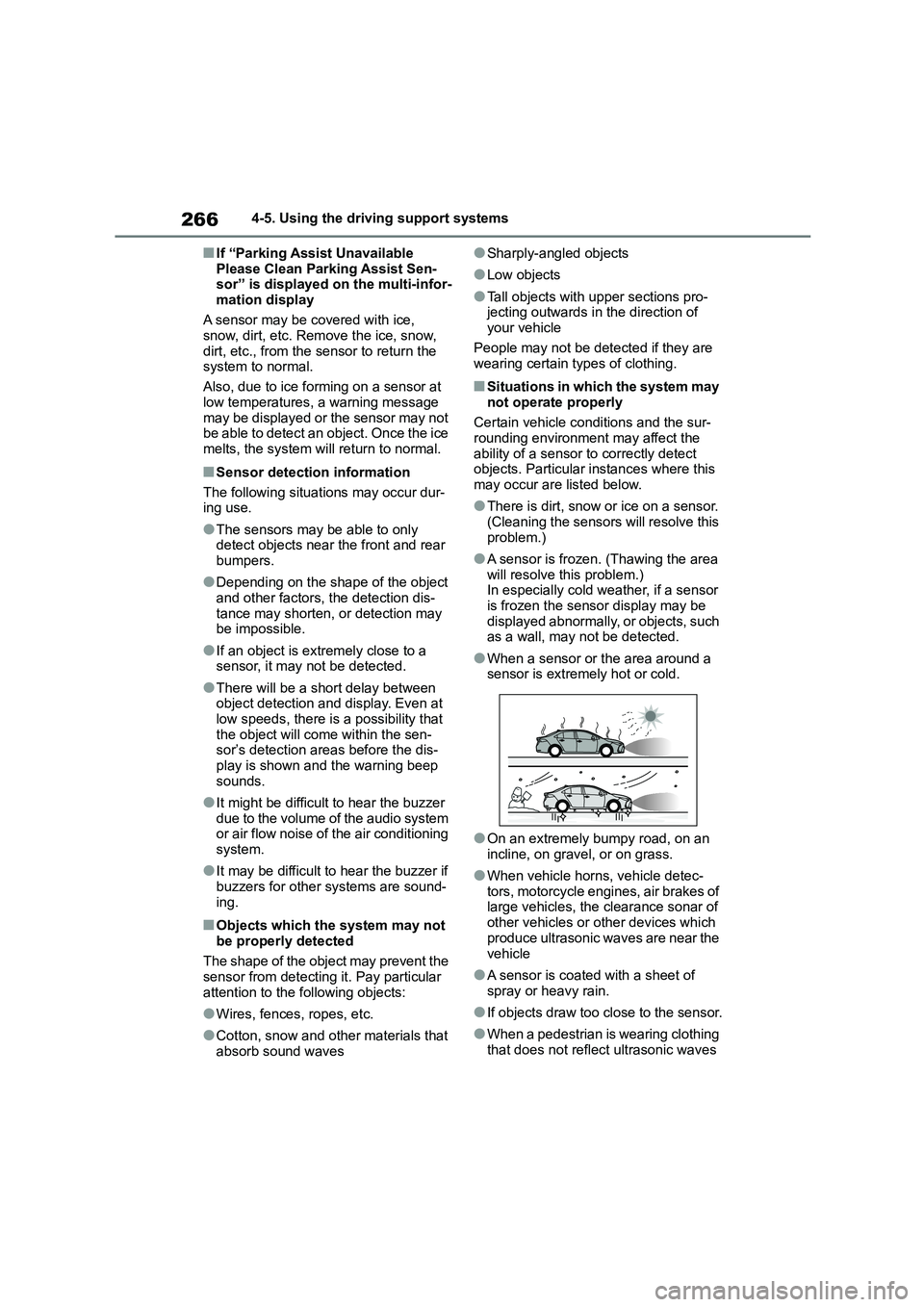
●When a sensor or the area around a
sensor is extremely hot or cold.
●On an extremely bumpy road, on an
incline, on gravel, or on grass.
●When vehicle horns, vehicle detec-
tors, motorcycle engines, air brakes of large vehicles, the clearance sonar of
other vehicles or other devices which
produce ultrasonic waves are near the
vehicle
●A sensor is coated with a sheet of
spray or heavy rain.
●If objects draw too close to the sensor.
●When a pedestrian is wearing clothing
that does not reflect ultrasonic waves
Page 318 of 678
3164-5. Using the driving support systems
■ABS (Anti-lock Brake System)
Helps to prevent wheel lock when
the brakes are applied suddenly, or
if the brakes are applied while driv-
ing on a slippery road surface
■Brake assist
Generates an increased level of
braking force after the brake pedal
is depressed when the system
detects a panic stop situation
■VSC (Vehicle St ability Control)
Helps the driver to control skidding
when swerving suddenly or turning
on slippery road surfaces.
■VSC+ (Vehicle Stability Con-
trol+)
Provides cooperative control of the
ABS, TRC, VSC and EPS.
Helps to maintain directional stabil-
ity when swerving on slippery road
surfaces by controlling steering per-
formance.
■TRC (Traction Control)
Helps to maintain drive power and
prevent the drive wheels from spin-
ning when starting the vehicle or
accelerating on slippery roads
■Active Cornering Assist (ACA)
Helps to prevent the vehicle from
drifting to the outer side by perform-
ing inner wheel brake control when
attempting to acce lerate while turn-
ing
■Hill-start assist control
Helps to reduce the backward
movement of the vehicle when
starting on an uphill
■EPS (Electric Po wer Steering)
Employs an electric motor to
reduce the amount of effort needed
to turn the steering wheel.
■Emergency brake signal
When the brakes are applied sud-
denly, the emergency flashers auto-
matically flash to alert the vehicle
behind.
■Secondary Collision Brake (if
equipped)
When the SRS airbag sensor
detects a collisi on and the system
operates, the brakes and brake
lights are automatically controlled
to reduce the vehicle speed and
help reduce the poss ibility of further
damage due to a secondary colli-
sion.
Driving assist systems
To keep driving safety and per-
formance, the following sys-
tems operate au tomatically in
response to various driving sit-
uations. Be aware, however,
that these systems are supple-
mentary and should not be
relied upon too heavily when
operating the vehicle.
Summary of the driving
assist systems