engine TOYOTA COROLLA HATCHBACK 2023 Owners Manual
[x] Cancel search | Manufacturer: TOYOTA, Model Year: 2023, Model line: COROLLA HATCHBACK, Model: TOYOTA COROLLA HATCHBACK 2023Pages: 436, PDF Size: 8.72 MB
Page 292 of 436
2926-3. Do-it-yourself maintenance
■Setting using the current
tire inflation pressure
4.2-inch display
1 Park the vehicle in a safe
place and then start the
engine.
The tire inflation pressure cannot
be set while the vehicle is moving.
2Select of the multi-infor-
mation display and then
press .
3 Press or to select
“Vehicle Settings” and then
press and hold .
4 Press or to select
“TPWS setting” and then
press .
5 Press or to select
“Tire Pressure Setting” and
then press .
6 Press or to select
“Setting by Current Pressure”
and then press .
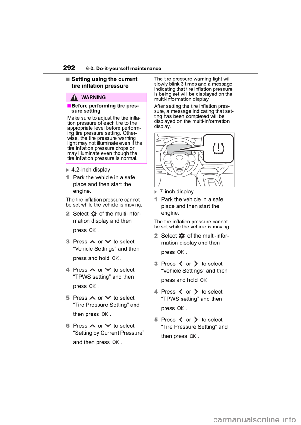
The tire pressure warning light will
slowly blink 3 times and a message
indicating that tire inflation pressure
is being set will be displayed on the
multi-information display.
After setting the tire inflation pres-
sure, a message indicating that set-
ting has been completed will be
displayed on the multi-information
display.
7-inch display
1 Park the vehicle in a safe
place and then start the
engine.
The tire inflation pressure cannot
be set while the ve hicle is moving.
2Select of the multi-infor-
mation display and then
press .
3 Press or to select
“Vehicle Settings” and then
press and hold .
4 Press or to select
“TPWS setting” and then
press .
5 Press or to select
“Tire Pressure Setting” and
then press .
WARNING
■Before performing tire pres-
sure setting
Make sure to adjust the tire infla-
tion pressure of each tire to the
appropriate level before perform-
ing tire pressure setting. Other-
wise, the tire pressure warning
light may not illuminate even if the
tire inflation pressure drops or
may illuminate ev en though the
tire inflation pressure is normal.
Page 293 of 436
2936-3. Do-it-yourself maintenance
6
Maintenance and care
6Press or to select
“Setting by Current Pressure”
and then press .
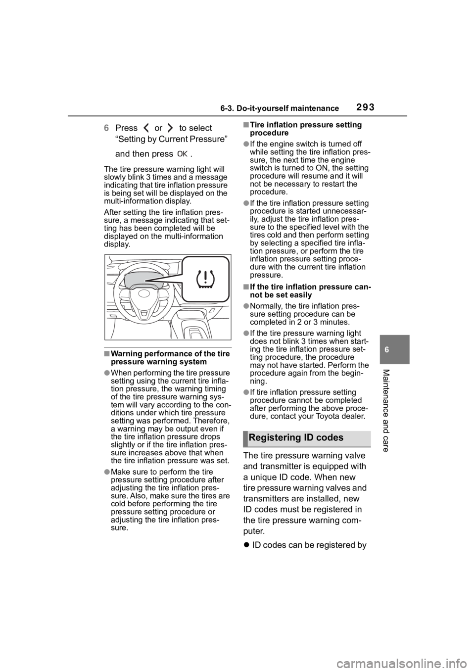
The tire pressure warning light will
slowly blink 3 times and a message
indicating that tire inflation pressure
is being set will be displayed on the
multi-information display.
After setting the tire inflation pres-
sure, a message indicating that set-
ting has been completed will be
displayed on the multi-information
display.
■Warning performance of the tire
pressure warning system
●When performing the tire pressure
setting using the current tire infla-
tion pressure, the warning timing
of the tire pressu re warning sys-
tem will vary accor ding to the con-
ditions under which tire pressure
setting was performed. Therefore,
a warning may be output even if
the tire inflation pressure drops
slightly or if the tire inflation pres-
sure increases above that when
the tire inflation pressure was set.
●Make sure to perform the tire
pressure setting procedure after
adjusting the tire inflation pres-
sure. Also, make sure the tires are
cold before performing the tire
pressure setting procedure or
adjusting the tire inflation pres-
sure.
■Tire inflation pressure setting
procedure
●If the engine switch is turned off
while setting the tir e inflation pres-
sure, the next time the engine
switch is turned to ON, the setting
procedure will resume and it will
not be necessary to restart the
procedure.
●If the tire inflation pressure setting
procedure is started unnecessar-
ily, adjust the tire inflation pres-
sure to the specified level with the
tires cold and then perform setting
by selecting a specified tire infla-
tion pressure, or perform the tire
inflation pressure setting proce-
dure with the curren t tire inflation
pressure.
■If the tire inflation pressure can-
not be set easily
●Normally, the tire inflation pres-
sure setting pro cedure can be
completed in 2 or 3 minutes.
●If the tire pressur e warning light
does not blink 3 times when start-
ing the tire inflation pressure set-
ting procedure, t he procedure
may not have started. Perform the
procedure again from the begin-
ning.
●If tire inflation pressure setting
procedure cannot be completed
after performing the above proce-
dure, contact your Toyota dealer.
The tire pressure warning valve
and transmitter is equipped with
a unique ID code. When new
tire pressure warning valves and
transmitters are installed, new
ID codes must be registered in
the tire pressure warning com-
puter.
ID codes can be registered by
Registering ID codes
Page 294 of 436
2946-3. Do-it-yourself maintenance
yourself, but depending on
the driving conditions and
driving environment, registra-
tion may take some time to
complete.
When using a wheel set
which all of the ID codes have
already been registered, the
wheel set can be changed in
a short amount of time.
Before performing ID code reg-
istration, make sure that no
wheels with tire pressure warn-
ing valve and transmitters
installed are near the vehicle.
4.2-inch display
1 Park the vehicle in a safe
place and turn the engine
switch off, wait for approxi-
mately 20 minutes or more,
and then start the engine.
The ID code registration procedure
cannot be performed while the
vehicle is moving.
2Select of the multi-infor-
mation display and then
press .
3 Press or to select
“Vehicle Settings” and then
press and hold .
4 Press or to select
“TPWS setting” and then
press . 5
Press or to select
“Tire Set Switching” and then
press .
6 Press or to select
“Register New Valve / ID” and
then press ..
7 Press or to select
“Tire Set 1” or “Tire Set 2”.
Then press .
ID codes will be regi stered to the
displayed wheel set.
If ID codes have already been reg-
istered for that wheel set, the tire
pressure warning light will slowly
blink 3 times, and a message indi-
cating that change is occurring will
be displayed on the multi-informa-
tion display.
8 Select “OK” and then press
.
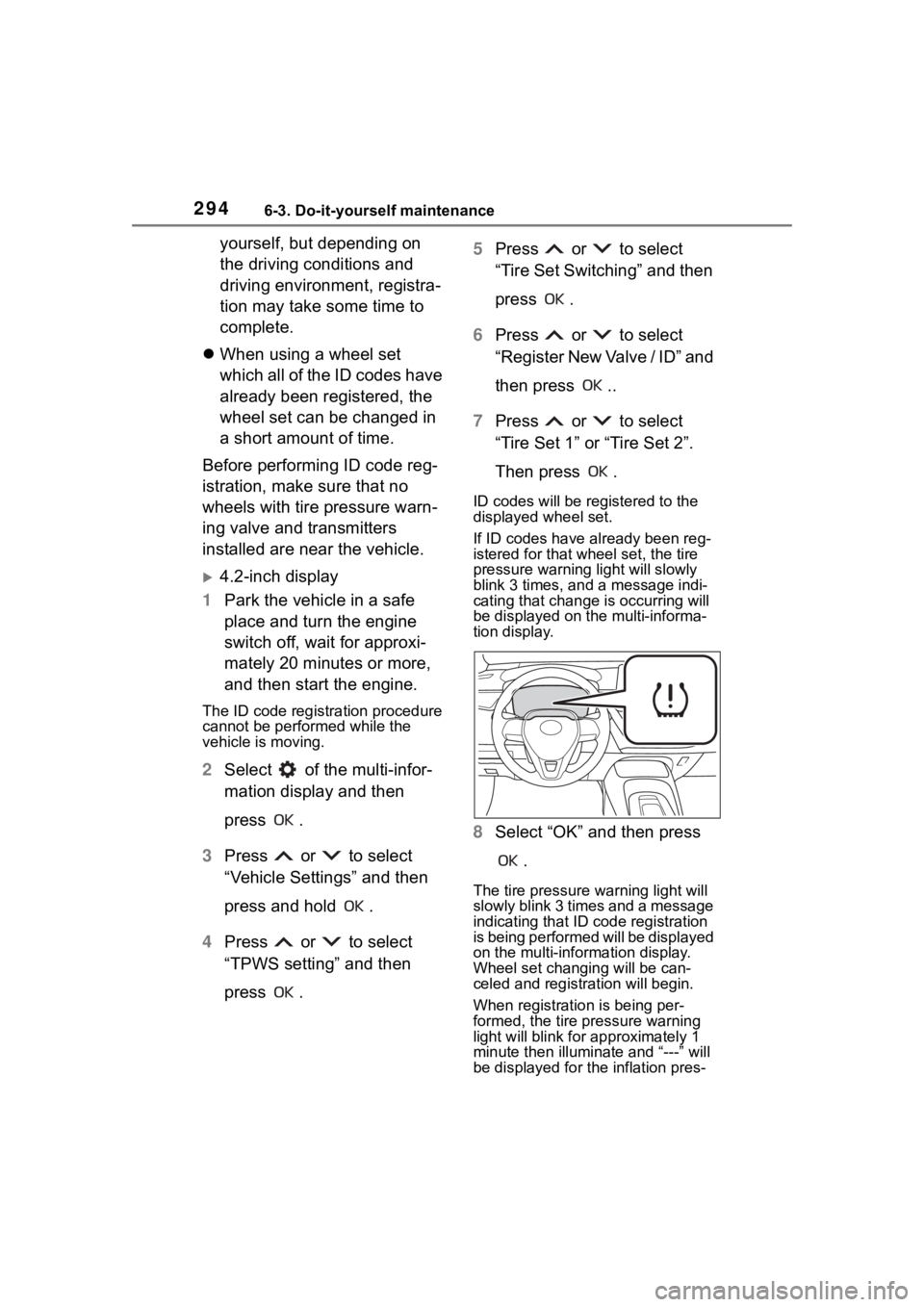
The tire pressure warning light will
slowly blink 3 times and a message
indicating that ID code registration
is being performed will be displayed
on the multi-information display.
Wheel set changing will be can-
celed and registration will begin.
When registration is being per-
formed, the tire pressure warning
light will blink for approximately 1
minute then illumina te and “---” will
be displayed for the inflation pres-
Page 295 of 436

2956-3. Do-it-yourself maintenance
6
Maintenance and care
sure of each tire on the multi-infor-
mation display.
9Drive straight (with occa-
sional left and right turns) at
approximately 25 mph (40
km/h) or more for approxi-
mately 10 to 30 minutes.
When registration is complete, the
tire pressure warni ng light will turn
off and a message indicating that
registration has been completed
will be displayed on the multi-infor-
mation display.
Registration may take longer than
normal to complete if the vehicle
speed cannot be maintained at
approximately 25 mph (40 km/h) or
more. If registration cannot be com-
pleted after driving for 1 hour or
more, perform the registration pro-
cedure again from the beginning.
10 If the tire inflation pressure of
the wheel set installed differs
from that of the previous set,
it will be necessary to per-
form the tire inflation pres-
sure setting procedure of the
tire pressure warning system.
If the specified tire inflation pres-
sure is the same, i t will not be nec-
essary to perform the tire inflation
pressure setting procedure.
7-inch display
1 Park the vehicle in a safe
place and turn the engine
switch off, wait for approxi-
mately 20 minutes or more,
and then start the engine.
The ID code registration procedure
cannot be performed while the
vehicle is moving.
2Select of the multi-infor-
mation display and then
press .
3 Press or to select
“Vehicle Settings” and then
press and hold .
4 Press or to select
“TPWS setting” and then
press .
5 Press or to select
“Tire Set Switching” and then
press .
6 Press or to select
“Register New Valve / ID” and
then press .
7 Press or to select
“Tire Set 1” or “Tire Set 2”.
Then press .
ID codes will be regi stered to the
displayed wheel set.
If ID codes have already been reg-
istered for that wheel set, the tire
pressure warning light will slowly
blink 3 times, and a message indi-
cating that change is occurring will
be displayed on the multi-informa-
tion display.
Page 303 of 436
3036-3. Do-it-yourself maintenance
6
Maintenance and care
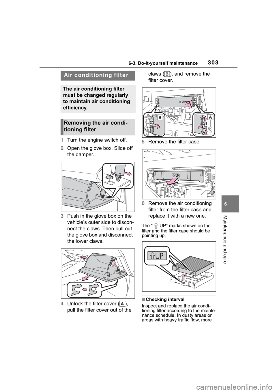
1Turn the engine switch off.
2 Open the glove box. Slide off
the damper.
3 Push in the glove box on the
vehicle’s outer side to discon-
nect the claws. Then pull out
the glove box and disconnect
the lower claws.
4 Unlock the filter cover ( ),
pull the filter cover out of the claws ( ), and remove the
filter cover.
5 Remove the filter case.
6 Remove the air conditioning
filter from the filter case and
replace it with a new one.
The “ UP” marks shown on the
filter and the filter case should be
pointing up.
■Checking interval
Inspect and replace the air condi-
tioning filter according to the mainte-
nance schedule. In dusty areas or
areas with heavy traffic flow, more
Air condition ing filter
The air conditioning filter
must be changed regularly
to maintain air conditioning
efficiency.
Removing the air condi-
tioning filter
Page 306 of 436

3066-3. Do-it-yourself maintenance
1Turn the engine switch off.
2 Open the fuse box cover.
Engine compartment: type A
fuse box
Push the tabs in and lift the lid off.
Engine compartment: type B
fuse box
Push the tabs in and lift the lid off.
WARNING
●If you accidentally swallow a
battery or put a b attery into a
part of your body, get emer-
gency medical attention imme-
diately.
■To prevent battery explosion
or leakage of flammable liq-
uid or gas
●Replace the battery with a new
battery of the same type. If a
wrong type of battery is used, it
may explode.
●Do not expose batteries to
extremely low pressure due to
high altitude or extremely high
temperatures.
●Do not burn, bre ak or cut a bat-
tery.
NOTICE
■When replacing the battery
Use a flathead screwdriver of
appropriate size. Applying exces-
sive force may deform or damage
the cover.
■For normal operation after
replacing the battery
Observe the following precautions
to prevent accidents:
●Always work with dry hands.
Moisture may cau se the battery
to rust.
●Do not touch or move any other
component inside the remote
control.
●Do not bend either of the battery
terminals.
Checking a nd replac-
ing fuses
If any of the electrical com-
ponents do not operate, a
fuse may have blown. If this
happens, check and replace
the fuses as necessary.
Checking and replacing
fuses
Page 311 of 436

311
7
7
When trouble arises
When trouble arises
.7-1. Essential informationEmergency flashers .... 312
If your vehicle has to be stopped in an emergency.................................. 312
If the vehicle is submerged or water on the road is ris-
ing ............................. 313
7-2. Steps to take in an emer- gency
If your vehicle needs to be towed......................... 315
If you think something is wrong ........................ 318
Fuel pump shut off system .................................. 319
If a warning light turns on or a warning buzzer sounds.................................. 320
If a warning message is dis- played........................ 330
If you have a flat tire (vehi- cles without spare tire).................................. 334
If you have a flat tire (vehi- cles with a spare tire).................................. 346
If the engine will not start .................................. 354
If you lose your keys ... 356
If the electronic key does not operate properly .. 356If the vehicle
battery is dis-
charged ..................... 358
If your vehicle overheats .................................. 362
If the vehicle becomes stuck .................................. 364
Page 312 of 436
3127-1. Essential information
7-1.Essential information
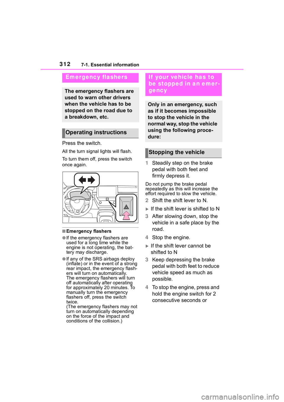
Press the switch.
All the turn signal lights will flash.
To turn them off, press the switch
once again.
■Emergency flashers
●If the emergency flashers are
used for a long time while the
engine is not operating, the bat-
tery may discharge.
●If any of the SRS airbags deploy
(inflate) or in the event of a strong
rear impact, the emergency flash-
ers will turn on automatically.
The emergency flashers will turn
off automatically after operating
for approximately 20 minutes. To
manually turn t he emergency
flashers off, press the switch
twice.
(The emergency flashers may not
turn on automatically depending
on the force of the impact and
conditions of the collision.)
1 Steadily step on the brake
pedal with both feet and
firmly depress it.
Do not pump the brake pedal
repeatedly as this will increase the
effort required to slow the vehicle.
2Shift the shift lever to N.
If the shift lever is shifted to N
3 After slowing down, stop the
vehicle in a safe place by the
road.
4 Stop the engine.
If the shift lever cannot be
shifted to N
3 Keep depressing the brake
pedal with both feet to reduce
vehicle speed as much as
possible.
4 To stop the engine, press and
hold the engine switch for 2
consecutive seconds or
Emergency flashers
The emergency flashers are
used to warn other drivers
when the vehicle has to be
stopped on the road due to
a breakdown, etc.
Operating instructions
If your vehicle has to
be stopped in an emer-
gency
Only in an emergency, such
as if it becomes impossible
to stop the vehicle in the
normal way, stop the vehicle
using the following proce-
dure:
Stopping the vehicle
Page 313 of 436
3137-1. Essential information
7
When trouble arises
more, or press it briefly 3
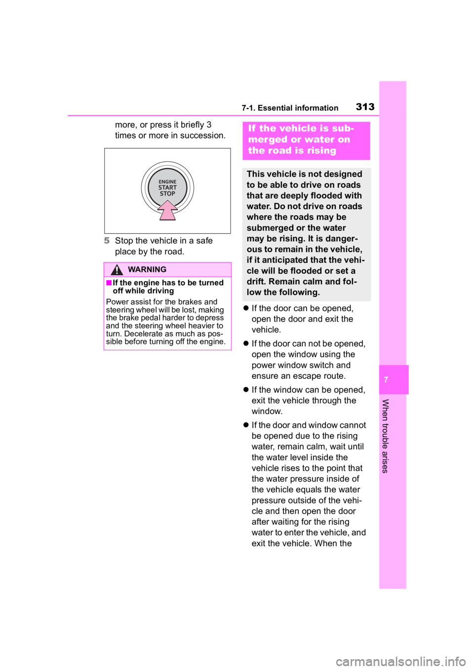
times or more in succession.
5 Stop the vehicle in a safe
place by the road.
If the door can be opened,
open the door and exit the
vehicle.
If the door can not be opened,
open the window using the
power window switch and
ensure an escape route.
If the window can be opened,
exit the vehicle through the
window.
If the door and window cannot
be opened due to the rising
water, remain calm, wait until
the water level inside the
vehicle rises to the point that
the water pressure inside of
the vehicle equals the water
pressure outside of the vehi-
cle and then open the door
after waiting for the rising
water to enter the vehicle, and
exit the vehicle. When the
WARNING
■If the engine has to be turned
off while driving
Power assist for the brakes and
steering wheel will be lost, making
the brake pedal harder to depress
and the steering wheel heavier to
turn. Decelerate as much as pos-
sible before turning off the engine.
If the vehicle is sub-
merged or water on
the road is rising
This vehicle is not designed
to be able to drive on roads
that are deeply flooded with
water. Do not drive on roads
where the roads may be
submerged or the water
may be rising. It is danger-
ous to remain in the vehicle,
if it anticipated that the vehi-
cle will be flooded or set a
drift. Remain calm and fol-
low the following.
Page 314 of 436

3147-1. Essential information
outside water level exceeds
half the height of the door, the
door cannot be opened from
the inside due to water pres-
sure.
■Water level exceeds the floor
When the water level exceeds the
floor and time has passed, the elec-
trical equipment will get damaged,
the power windows will not operate,
the engine stop, and the vehicle
may not be able to get moving.
■Using an emergency escape
hammer*
Laminated glass is used in the wind-
shield on this vehicle.
Laminated glass cannot be shat-
tered with an emergency hammer
*.
Tempered glass is used in the win-
dows on this vehicle.
*: Contact your Toyota dealer or
aftermarket accessory manufac-
turer for further information about
an emergency hammer.
WARNING
■Caution while driving
Do not drive on roads where the
roads may be submerged or the
water may be rising. Otherwise
the vehicle may be damaged and
cannot move, as well as become
flooded and set a drift, which may
lead to death.