ECU TOYOTA FR-S 2015 (in English) Owner's Guide
[x] Cancel search | Manufacturer: TOYOTA, Model Year: 2015, Model line: FR-S, Model: TOYOTA FR-S 2015Pages: 452, PDF Size: 9.97 MB
Page 202 of 452
202 2-4. Using other driving systems
Disabling the TRAC system
If the vehicle gets stuck in mud, dirt or snow, the TRAC system may
reduce power from the engine to the wheels. Pressing to turn
the system off may make it easier for you to rock the vehicle in order
to free it.
In this case, the brake LSD function remains on.
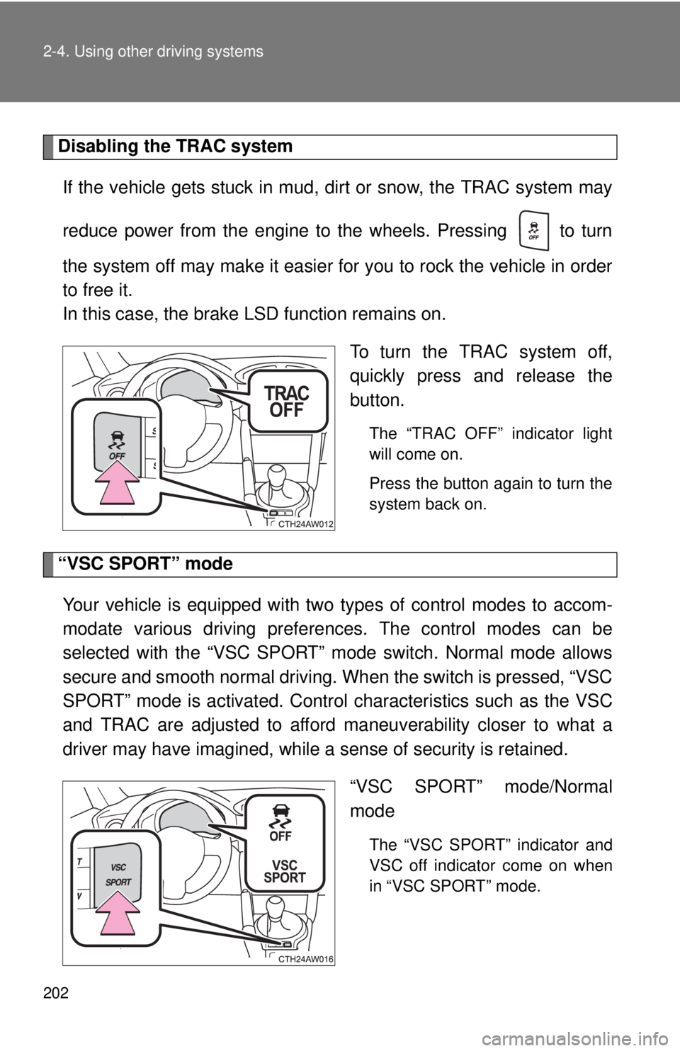
To turn the TRAC system off,
quickly press and release the
button.
The “TRAC OFF” indicator light
will come on.
Press the button again to turn the
system back on.
“VSC SPORT” mode
Your vehicle is equipped with two types of control modes to accom-
modate various driving preferences. The control modes can be
selected with the “VSC SPORT” mode switch. Normal mode allows
secure and smooth normal driving. When the switch is pressed, “VSC
SPORT” mode is activated. Control characteristics such as the VSC
and TRAC are adjusted to afford maneuverability closer to what a
driver may have imagined, while a sense of security is retained.
“VSC SPORT” mode/Normal
mode
The “VSC SPORT” indicator and
VSC off indicator come on when
in “VSC SPORT” mode.
Page 207 of 452
207
2
When driving
2-5. Driving information
Cargo and luggage
Capacity and distribution
Cargo capacity depends on the total weight of the occupants.
(Cargo capacity) = (Total load capacity) - (Total weight of occupants)
Steps for Determining Correct Load Limit
(1)Locate the statement “The combined weight of occupants and
cargo should never exceed XXX kg or XXX lbs.” on your vehicle's
placard.
(2)Determine the combined weight of the driver and passengers that
will be riding in your vehicle.
(3)Subtract the combined weight of the driver and passengers from
XXX kg or XXX lbs.
(4)The resulting figure equals the available amount of cargo and lug-
gage load capacity.
For example, if the “XXX” amount equals 1400 lbs. and there will
be five 150 lb passengers in your vehicle, the amount of available
cargo and luggage load capacity is 650 lbs. (1400 - 750 (5 150) =
650 lbs.)
(5)Determine the combined weight of luggage and cargo being
loaded on the vehicle. That weight may not safely exceed the avail-
able cargo and luggage load capacity calculated in Step 4.
Take notice of the following information about storage precau-
tions, cargo capacity and load:
●Stow cargo and luggage in the trunk whenever possible.
●Be sure all items are secured in place.
●To maintain vehicle balance while driving, position luggage
evenly within the luggage compartment.
●For better fuel economy, do not carry unnecessary weight.
Page 210 of 452

210 2-5. Driving information
CAUTION
■Storage precautions
Observe the following precautions.
Failure to do so may result in death or serious injury.
●Stow cargo and luggage in the trunk whenever possible.
●To prevent cargo and luggage from sliding forward during braking, do
not stack anything in the enlarged trunk. Keep cargo and luggage low,
as close to the floor as possible.
●When you fold down the rear seats, long items should not be placed
directly behind the front seats.
●Never allow anyone to ride in the enlarged trunk. It is not designed for
passengers. They should ride in their seats with their seat belts prop-
erly fastened. Otherwise, they are much more likely to suffer death or
serious bodily injury, in the event of sudden braking, sudden swerving
or an accident.
●Do not place cargo or luggage in or on the following locations as the
item may get under the clutch, brake or accelerator pedal and prevent
the pedals from being depressed properly, block the driver’s vision, or
hit the driver or passengers, causing an accident:
• At the feet of the driver
• On the front passenger or rear seats (when stacking items)
• On the package tray
• On the instrument panel
• On the dashboard
●Secure all items in the occupant compartment, as they may shift and
injure someone during sudden braking, sudden swerving or an acci-
dent.
■Capacity and distribution
●Do not exceed the maximum axle weight rating or the total vehicle
weight rating.
●Even if the total load of occupant's weight and the cargo load is less
than the total load capacity, do not apply the load unevenly. Improper
loading may cause deterioration of steering or braking control which
may cause death or serious injury.
Page 239 of 452
239 3-4. Using the storage features
3
Interior features
CAUTION
■Caution while driving
Observe the following precautions.
Failure to do so may cause an accident resulting in death or serious injury.
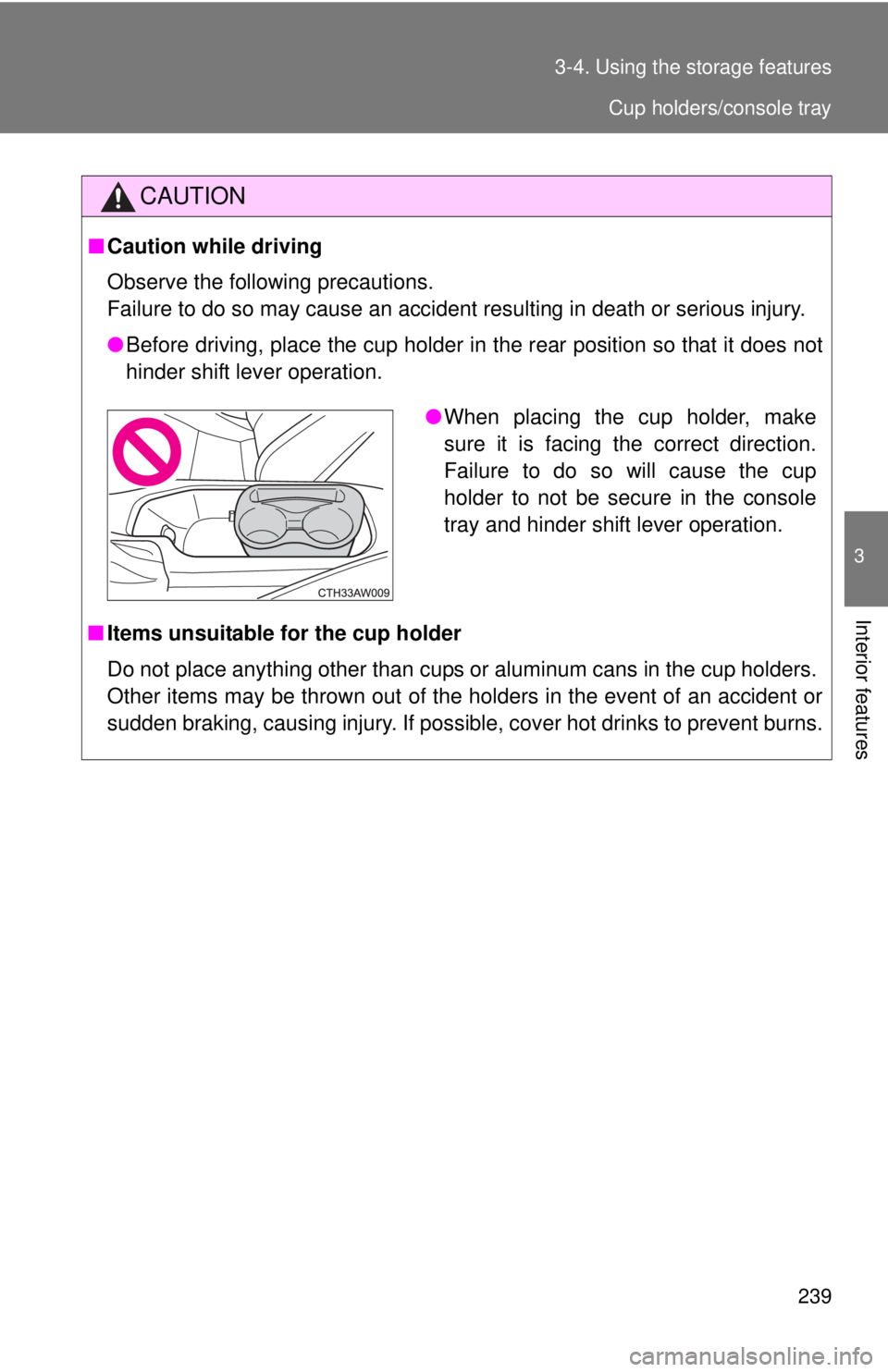
●Before driving, place the cup holder in the rear position so that it does not
hinder shift lever operation.
■Items unsuitable for the cup holder
Do not place anything other than cups or aluminum cans in the cup holders.
Other items may be thrown out of the holders in the event of an accident or
sudden braking, causing injury. If possible, cover hot drinks to prevent burns.
●When placing the cup holder, make
sure it is facing the correct direction.
Failure to do so will cause the cup
holder to not be secure in the console
tray and hinder shift lever operation.
Cup holders/console tray
Page 246 of 452
246
3-5. Other interior features
Floor mat
Use only floor mats designed specifically for vehicles of the same
model and model year as your vehicle. Fix them securely in place
onto the carpet.
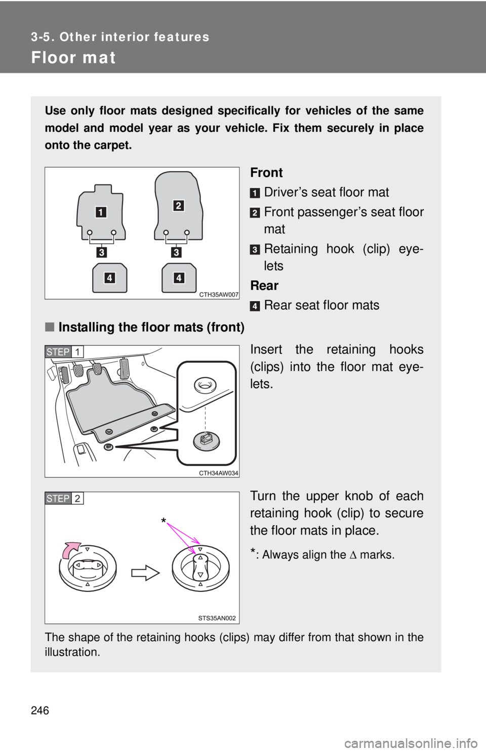
Front
Driver’s seat floor mat
Front passenger’s seat floor
mat
Retaining hook (clip) eye-
lets
Rear
Rear seat floor mats
■Installing the floor mats (front)
Insert the retaining hooks
(clips) into the floor mat eye-
lets.
Turn the upper knob of each
retaining hook (clip) to secure
the floor mats in place.
*: Always align the marks.
The shape of the retaining hooks (clips) may differ from that shown in the
illustration.
STEP 1
STEP 2
*
Page 247 of 452
247 3-5. Other interior features
3
Interior features
CAUTION
Observe the following precautions.
Failure to do so may cause the driver's floor mat to slip, possibly interfering
with the pedals while driving. An unexpectedly high speed may result or it may
become difficult to stop the vehicle, leading to a serious accident, resulting in
death or serious injury.
■When installing a floor mat
●Do not use floor mats designed for other models or different model year
vehicles, even if they are Scion Genuine floor mats.
●Driver’s seat floor mat: Only use floor mats designed for the driver's seat.
●Front: Always install the floor mat securely using the retaining hooks (clips)
provided.
●Do not use two or more floor mats on top of each other.
●Do not place the floor mat bottom-side up or upside-down.
■Before driving
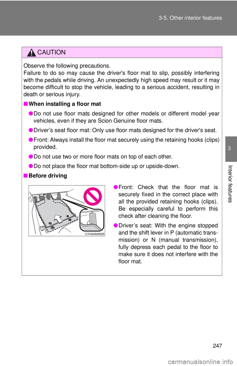
●Front: Check that the floor mat is
securely fixed in the correct place with
all the provided retaining hooks (clips).
Be especially careful to perform this
check after cleaning the floor.
●Driver’s seat: With the engine stopped
and the shift lever in P (automatic trans-
mission) or N (manual transmission),
fully depress each pedal to the floor to
make sure it does not interfere with the
floor mat.
Page 261 of 452
261 4-2. Maintenance
4
Maintenance and care
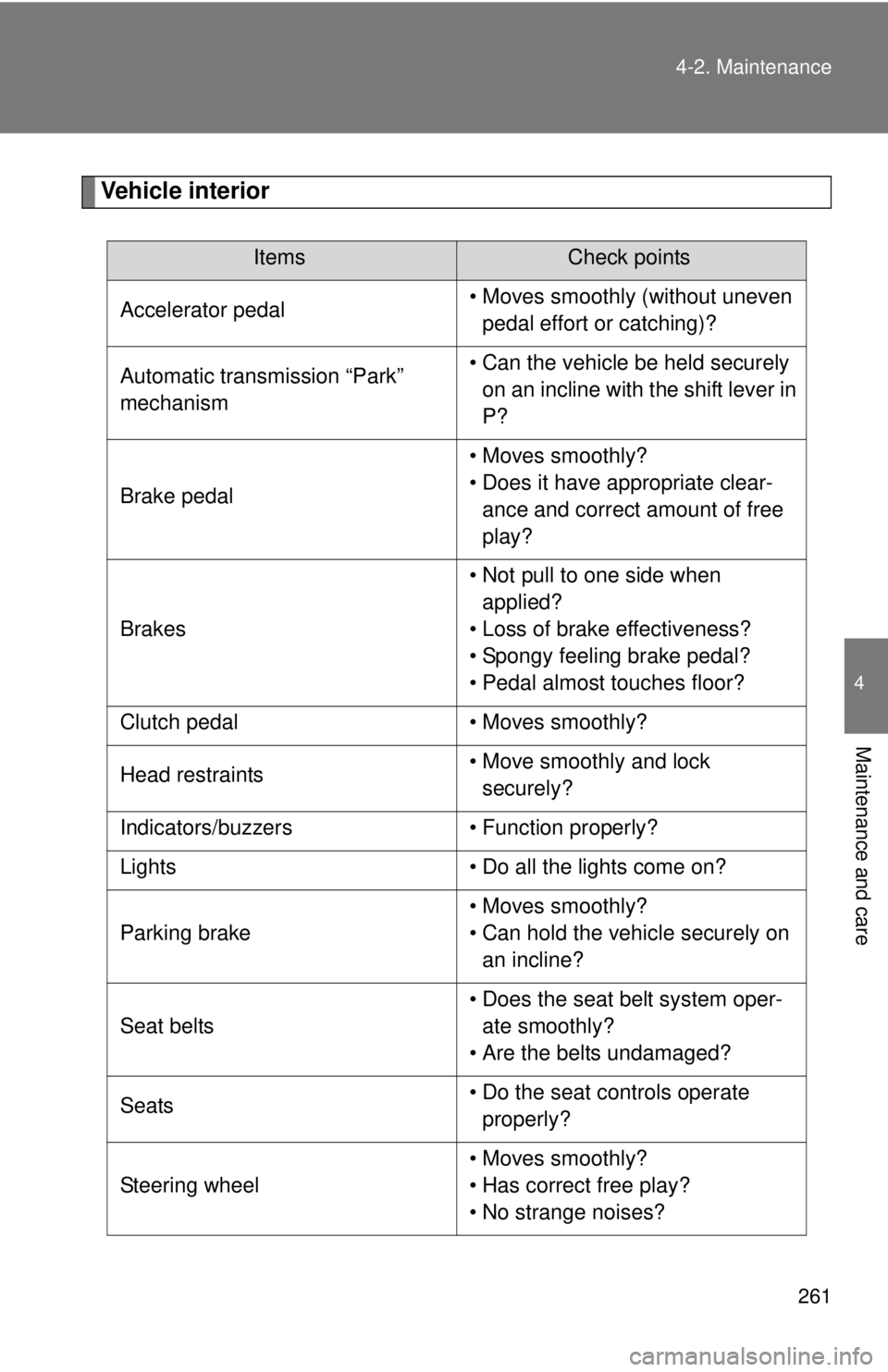
Vehicle interior
ItemsCheck points
Accelerator pedal• Moves smoothly (without uneven
pedal effort or catching)?
Automatic transmission “Park”
mechanism• Can the vehicle be held securely
on an incline with the shift lever in
P?
Brake pedal• Moves smoothly?
• Does it have appropriate clear-
ance and correct amount of free
play?
Brakes• Not pull to one side when
applied?
• Loss of brake effectiveness?
• Spongy feeling brake pedal?
• Pedal almost touches floor?
Clutch pedal • Moves smoothly?
Head restraints• Move smoothly and lock
securely?
Indicators/buzzers • Function properly?
Lights • Do all the lights come on?
Parking brake• Moves smoothly?
• Can hold the vehicle securely on
an incline?
Seat belts• Does the seat belt system oper-
ate smoothly?
• Are the belts undamaged?
Seats• Do the seat controls operate
properly?
Steering wheel• Moves smoothly?
• Has correct free play?
• No strange noises?
Page 280 of 452

280 4-3. Do-it-yourself maintenance
Remove the vent plug.
Add distilled water.
If the “UPPER LEVEL” line cannot be seen, check the fluid level by
looking directly at the cell.
Put the vent plug back on and close securely.
■Before recharging
When recharging, the battery produces hydrogen gas which is flammable
and explosive. Therefore, before recharging:
●If recharging with the battery installed on the vehicle, be sure to discon-
nect the ground cable.
●Make sure the power switch on the charger is off when connecting and
disconnecting the charger cables to the battery.
■After recharging/reconnecting the battery
●Unlocking the doors using the smart key system may not be possible
immediately after reconnecting the battery. If this happens, use the wire-
less remote control or the mechanical key to lock/unlock the doors.
●Start the engine with the “ENGINE START STOP” switch in ACCES-
SORY mode. The engine may not start with the “ENGINE START STOP”
switch turned off. However, the engine will operate normally from the sec-
ond attempt.
●The “ENGINE START STOP” switch mode is recorded by the vehicle. If
the battery is reconnected, the vehicle will return the “ENGINE START
STOP” switch mode to the status it was in before the battery was discon-
nected. Make sure to turn off the engine before disconnect the battery.
Take extra care when connecting the battery if the “ENGINE START
STOP” switch mode prior to discharge is unknown.
If the engine will not start even after multiple attempts, contact your Scion
dealer.
STEP 1
STEP 2
STEP 3
Page 307 of 452
307 4-3. Do-it-yourself maintenance
4
Maintenance and care
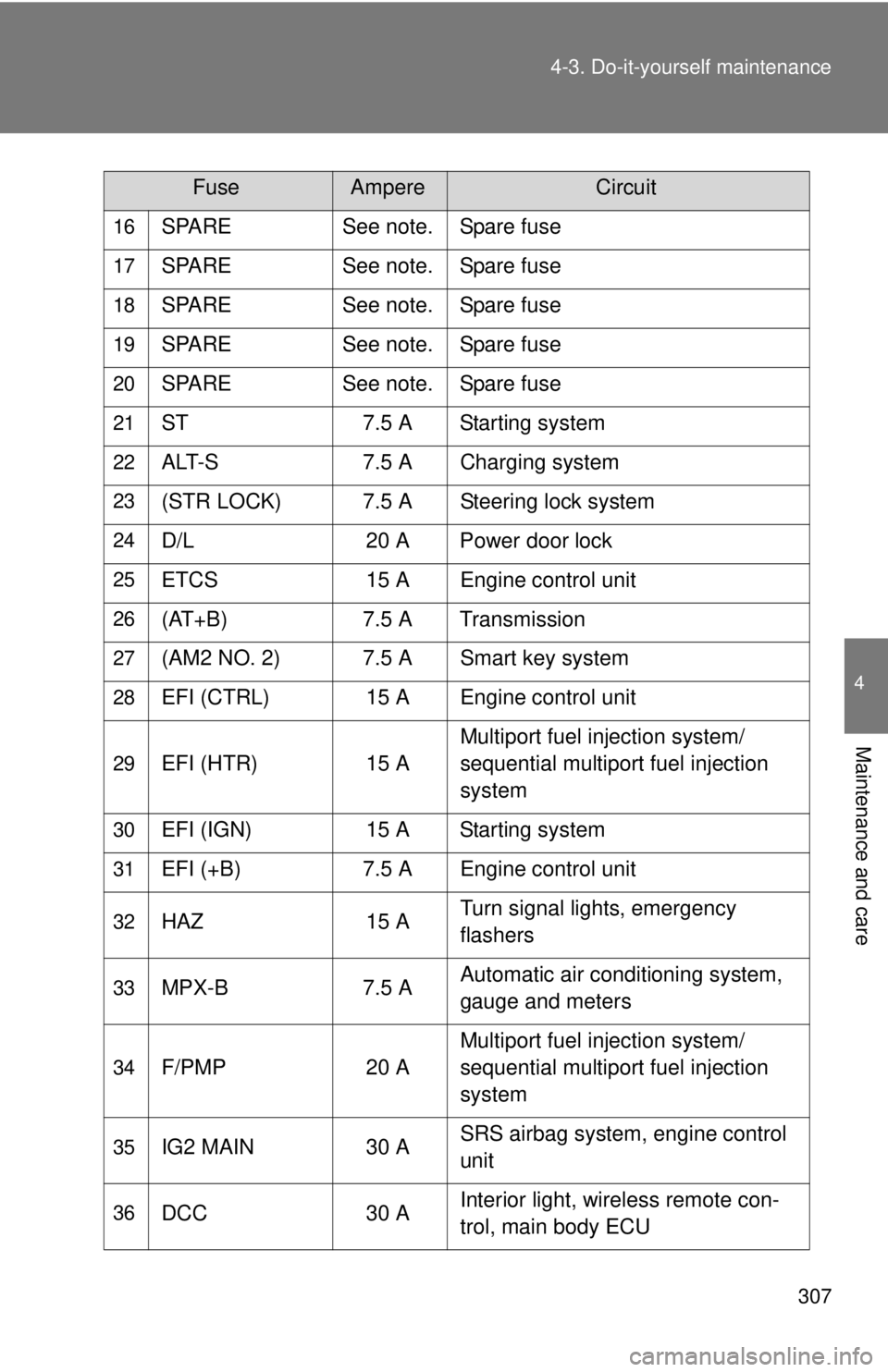
16SPARE See note. Spare fuse
17SPARE See note. Spare fuse
18SPARE See note. Spare fuse
19SPARE See note. Spare fuse
20SPARE See note. Spare fuse
21ST 7.5 A Starting system
22ALT-S 7.5 A Charging system
23(STR LOCK) 7.5 A Steering lock system
24D/L 20 A Power door lock
25ETCS 15 A Engine control unit
26(AT+B) 7.5 A Transmission
27(AM2 NO. 2) 7.5 A Smart key system
28EFI (CTRL) 15 A Engine control unit
29EFI (HTR) 15 AMultiport fuel injection system/
sequential multiport fuel injection
system
30EFI (IGN) 15 A Starting system
31EFI (+B) 7.5 A Engine control unit
32HAZ 15 ATurn signal lights, emergency
flashers
33MPX-B 7.5 AAutomatic air conditioning system,
gauge and meters
34F/PMP 20 AMultiport fuel injection system/
sequential multiport fuel injection
system
35IG2 MAIN 30 ASRS airbag system, engine control
unit
36DCC 30 AInterior light, wireless remote con-
trol, main body ECU
FuseAmpereCircuit
Page 308 of 452

308 4-3. Do-it-yourself maintenance
Note
One of each of the following spare fuses are provided: 7.5 A, 10 A, 15
A, 20 A, 25 A, 30 A.
37HORN NO. 2 7.5 A Horn
38HORN NO. 1 7.5 A Horn
39H-LP LH LO 15 A Left-hand headlight (low beam)
40H-LP RH LO 15 A Right-hand headlight (low beam)
41H-LP LH HI 10 A Left-hand headlight (high beam)
42H-LP RH HI 10 A Right-hand headlight (high beam)
43INJ 30 AMultiport fuel injection system/
sequential multiport fuel injection
system
44H-LP WASHER 30 A
45AM2 NO. 1 40 A Starting system, engine control unit
46EPS 80 A Electric power steering
47A/B MAIN 15 A SRS airbag system
48ECU-B 7.5 AWireless remote control, main body
ECU
49DOME 20 A Interior light
50IG2 7.5 A Engine control unit
FuseAmpereCircuit