TOYOTA GR SUPRA 2022 Owners Manual
Manufacturer: TOYOTA, Model Year: 2022, Model line: GR SUPRA, Model: TOYOTA GR SUPRA 2022Pages: 356, PDF Size: 39.14 MB
Page 231 of 356
2313-1. CONTROLS
3
CONTROLS
quickly removed from the wind-
shield and the front side win-
dows.
The LED is illuminated with the
system switched on.
The air flow can be adjusted
manually with the system
switched on.
The function is available with the
engine running.
The rear window defroster
switches off automatically after a
certain period of time.
The microfilter removes dust
and pollen from the incoming air.
Have this filter changed during
vehicle maintenance, refer to
page 301.The air flow directions can be
individually adjusted.
The air flow directions can be
adjusted for direct or indirect
ventilation.
Open the vents and position
them to ensure effective climate
control.
The air flow is directed towards
the passengers. The air flow
heats or cools noticeably,
depending on the adjusted tem-
perature.
The air flow is not directed
towards the passengers. The
car's interior is warmed or
cooled indirectly, depending on
the set temperature.
Switching on/off
Press the button.
If there is any window
condensation, press the
button on the driver's
side or switch on the air
conditioning. Make sure
that air can flow to the
windshield.
Rear window defroster
Press the button. The
LED lights up.
Microfilter
Ventilation
Concept
Adjusting the ventilation
General information
Direct ventilation
Indirect ventilation
Page 232 of 356
2323-1. CONTROLS
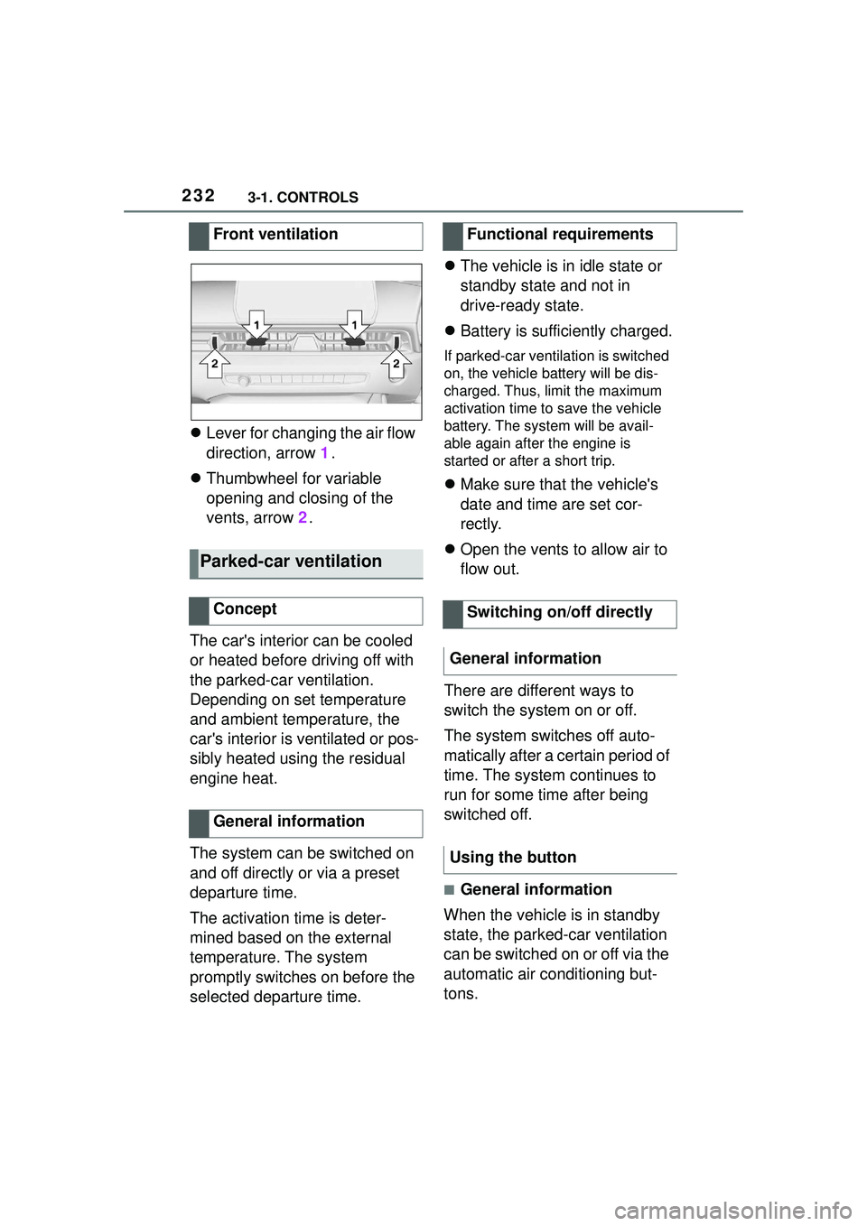
Lever for changing the air flow
direction, arrow 1.
Thumbwheel for variable
opening and closing of the
vents, arrow 2.
The car's interior can be cooled
or heated before driving off with
the parked-car ventilation.
Depending on set temperature
and ambient temperature, the
car's interior is ventilated or pos-
sibly heated using the residual
engine heat.
The system can be switched on
and off directly or via a preset
departure time.
The activation time is deter-
mined based on the external
temperature. The system
promptly switches on before the
selected departure time.
The vehicle is in idle state or
standby state and not in
drive-ready state.
Battery is sufficiently charged.
If parked-car ventilation is switched
on, the vehicle battery will be dis-
charged. Thus, limit the maximum
activation time to save the vehicle
battery. The system will be avail-
able again after the engine is
started or after a short trip.
Make sure that the vehicle's
date and time are set cor-
rectly.
Open the vents to allow air to
flow out.
There are different ways to
switch the system on or off.
The system switches off auto-
matically after a certain period of
time. The system continues to
run for some time after being
switched off.
■General information
When the vehicle is in standby
state, the parked-car ventilation
can be switched on or off via the
automatic air conditioning but-
tons.
Front ventilation
Parked-car ventilation
Concept
General information
Functional requirements
Switching on/off directly
General information
Using the button
Page 233 of 356
2333-1. CONTROLS
3
CONTROLS
■Switching on
Press any button except:
Rear window defroster.
Lower air flow button side.
Seat heating.
Menu.
■Switching off
The system switches off after
leaving and locking the vehicle.
Press and hold the bot-
tom button.
1 "My Vehicle"
2 "Vehicle settings"
3 "Climate functions"
4 "Comfort ventilation"
5 "Activate now" Different departure times can be
adjusted to ensure a comfort-
able interior temperature in the
vehicle at the time of departure.
One-time departure time: the
time can be set.
The system is switched on once.
Departure time with week-
day: time and day of the week
can be set.
On the desired weekdays, the sys-
tem will be switched on promptly
before the set departure time.
The departure time is prese-
lected in two steps:
Set departure times.
Activate departure times.
A minimum of 10 minutes
should pass between set-
ting/activating the departure
time and the planned departure
time to allow a sufficient period
of time for the climate control.
■Via Toyota Supra Command
1 "My Vehicle"
2 "Vehicle settings"
3 "Climate functions"
4 "Comfort ventilation"
5 Select the desired departure
time.
Via Toyota Supra Command
Display
SymbolDescription
Symbol on the auto-
matic air conditioning
indicates the system is
switched on.
REST is displayed on
the automatic air condi-
tioning. The residual
engine heat is used.
Departure time
Concept
Setting the departure time
Page 234 of 356
2343-1. CONTROLS
6Set the departure time.
7 Select day of the week, if
needed.
■Functional requirement
If a departure time is to influ-
ence the switching on of
parked-car ventilation, the
respective departure time must
be activated first.
■Via Toyota Supra Command
1 "My Vehicle"
2 "Vehicle settings"
3 "Climate functions"
4 "Comfort ventilation"
5 "For departure time"
6 Activate the desired depar-
ture time.
The symbol on the automatic
air conditioning signals an acti-
vated departure time. This chapter describes all stan-
dard, country-specific and
optional features offered with
the series. It also describes fea-
tures and functions that are not
necessarily available in your
vehicle, e.g., due to the selected
options or country versions. This
also applies to safety-related
functions and systems. When
using these functions and sys-
tems, the applicable laws and
regulations must be observed.
The integrated Universal
Remote Control in the interior
mirror can operate up to 3 func-
tions of remote-controlled sys-
tems such as garage door
drives, barriers, or lighting sys-
tems.
The Integrated Universal
Remote Control replaces up to 3
different hand-held transmitters.
To operate the remote control,
the buttons on the interior mirror
must be programmed with the
Activating the departure time
Display
Interior equipment
Vehicle features and
options
Integrated Universal
Remote Control
Concept
General information
Page 235 of 356
2353-1. CONTROLS
3
CONTROLS
desired functions. The
hand-held transmitter for the
particular system is required in
order to program the remote
control.
Before selling the vehicle, delete
the stored functions for the sake
of security.
If possible, do not install the
antenna of the remote-con-
trolled system, e.g. the garage
door drive, near metal objects to
ensure the best possible opera-
tion.Additional questions are
answered by:
Your Toyota dealer.
www.homelink.com on the
Internet.
HomeLink is a registered trade-
mark of Gentex Corporation.
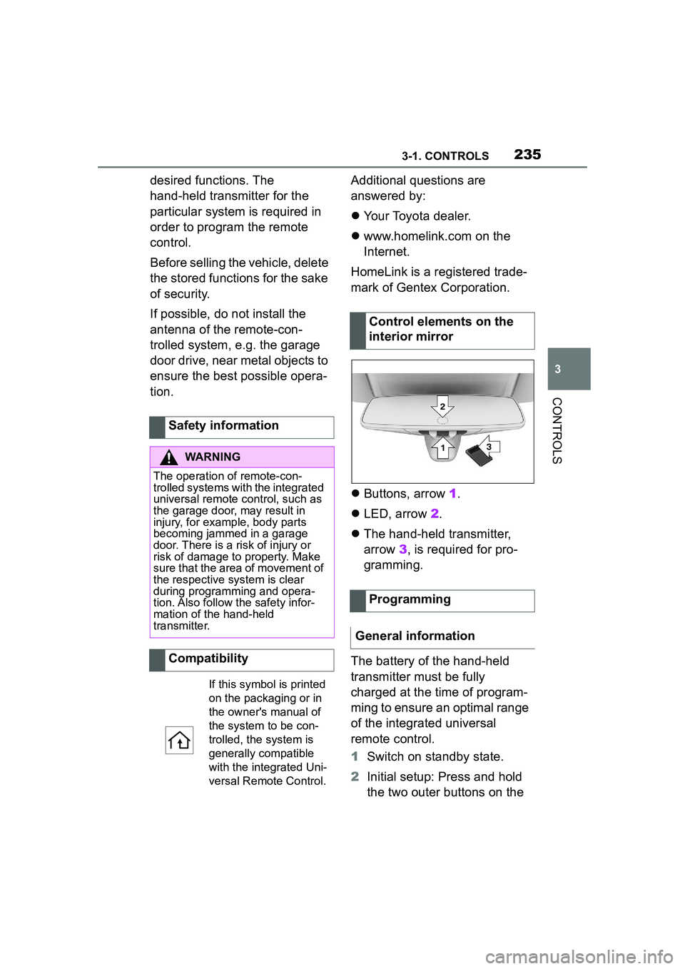
Buttons, arrow 1.
LED, arrow 2.
The hand-held transmitter,
arrow 3, is required for pro-
gramming.
The battery of the hand-held
transmitter must be fully
charged at the time of program-
ming to ensure an optimal range
of the integrated universal
remote control.
1 Switch on standby state.
2 Initial setup: Press and hold
the two outer buttons on the
Safety information
WARNING
The operation of remote-con-
trolled systems with the integrated
universal remote control, such as
the garage door, may result in
injury, for example, body parts
becoming jammed in a garage
door. There is a risk of injury or
risk of damage to property. Make
sure that the area of movement of
the respective system is clear
during programming and opera-
tion. Also follow the safety infor-
mation of the hand-held
transmitter.
Compatibility
If this symbol is printed
on the packaging or in
the owner's manual of
the system to be con-
trolled, the system is
generally compatible
with the integrated Uni-
versal Remote Control.
Control elements on the
interior mirror
Programming
General information
Page 236 of 356
2363-1. CONTROLS
interior mirror simultaneously
for approximately 10 seconds
until the LED flashes green
rapidly. This erases all pro-
gramming of the buttons on
the interior mirror.
3 Press the interior mirror but-
ton to be programmed. The
LED on the interior mirror will
slowly begin flashing orange.
4 Hold the hand-held transmit-
ter for the system to be used
approx. 1 to 12 in/2.5 to 30
cm away from the buttons on
the interior mirror. The
required distance depends
on the hand-held transmitter.
5 Press and hold the button of
the desired function on the
hand-held transmitter.
Canada: if programming with the
hand-held transmitter was inter-
rupted, hold down the interior mirror
button and repeatedly press and
release the hand-held transmitter
button for 2 seconds.
6
The LED lights up green: pro-
gramming completed.
Release the button.
The LED flashes fast: pro-
gramming is not complete.
Press the button on the interior mir-
ror for 2 seconds and release. Per-
form this procedure three times to
complete the programming proce-
dure.
If the integrated universal remote
control remains nonoperational,
continue with the special features for change code wireless systems.
LED does not flash green
after 60 seconds: program-
ming not completed.
Repeat steps 3 to 6.
To program other functions on
other buttons, repeat steps 3 to
5.
If you are unable to operate the
remote-controlled system after
repeated programming, please
check if the system to be con-
trolled features a rolling code
radio system.
Refer to the owner's manual for
the system.
For systems with a rolling code
radio system, the integrated
Universal Remote Control and
the system also have to be syn-
chronized.
Please read the owner's manual
to find out how to synchronize
the system.
Synchronizing is easier with the
aid of a second person.
Synchronizing the universal
remote control with the system:
1 Park the vehicle within range
of the remote-controlled sys-
tem.
2 Program the relevant button
on the interior mirror as
described.
Special feature of the rolling
code wireless system
Page 237 of 356
2373-1. CONTROLS
3
CONTROLS
3Locate and press the syn-
chronizing button on the sys-
tem being programmed, e.g.
at the garage gate. You have
approx. 30 seconds for the
next step.
4 Hold down the programmed
button on the interior mirror
for approximately 3 seconds
and then release it. If neces-
sary, repeat this step up to
three times in order to finish
synchronization. Once syn-
chronization is complete, the
programmed function will be
carried out.
1 Switch on standby state.
2 Press and hold the interior
mirror button to be pro-
grammed.
3 As soon as the LED on the
interior mirror flashes orange
after approx. 20 seconds,
release the button.
4 Hold the hand-held transmit-
ter for the system to be used
approx. 1 to 12 in/2.5 to 30
cm away from the buttons on
the interior mirror. The
required distance depends
on the hand-held transmitter.
5 Press and hold the button of
the desired function on the
hand-held transmitter.
Canada: if programming with the hand-held transmitter was inter-
rupted, hold down the interior mirror
button and repeatedly press and
release the hand-held transmitter
button for 2 seconds.
6
The LED can light up in dif-
ferent ways.
The LED lights up green: the
programming procedure is
completed.
Release the button.
The LED flashes fast: the
hand-held transmitter was
detected but programming is
not complete.
Press the button on the interior mir-
ror for 2 seconds and release. Per-
form this procedure three times to
complete the programming proce-
dure.
If the universal remote control
remains nonoperational, continue
with the special features for change
code wireless systems.
LED does not flash green
after 60 seconds: program-
ming not completed.
Repeat steps 3 to 6.
If the programming procedure is
not completed, the previous pro-
gramming will remain
unchanged.
Reprogramming individ-
ual buttons
Page 238 of 356
2383-1. CONTROLS
The system, such as the garage
door, can be operated using the
button on the interior mirror
while the drive-ready or standby
state is switched on. To do this,
hold down the button within
receiving range of the system
until the function is activated.
The interior mirror LED stays lit
while the wireless signal is being
transmitted.
All stored functions will be
deleted. The functions cannot
be deleted individually.
Press and hold the two outer
buttons on the interior mirror
simultaneously for approxi-
mately 10 seconds until the LED
on the interior mirror flashes
green rapidly.Fold the sun visor down or up.
A vanity mirror is located in the
sun visor behind a cover. When
the cover is opened, the mirror
lighting switches on.
The lighter socket can be used
as a socket for electrical equip-
ment when standby and
drive-ready state are switched
on.
The total load of all sockets
must not exceed 140 watts at 12
volts.
Do not damage the socket by
using non-compatible connec-
tors.
Operation
WARNING
The operation of remote-con-
trolled systems with the integrated
universal remote control, such as
the garage door, may result in
injury, for example, body parts
becoming jammed in a garage
door. There is a risk of injury or
risk of damage to property. Make
sure that the area of movement of
the respective system is clear
during programming and opera-
tion. Also follow the safety infor-
mation of the hand-held
transmitter.
Deleting stored functions
Sun visor
Glare shield
Vanity mirror
Sockets
Concept
General information
Page 239 of 356
2393-1. CONTROLS
3
CONTROLS
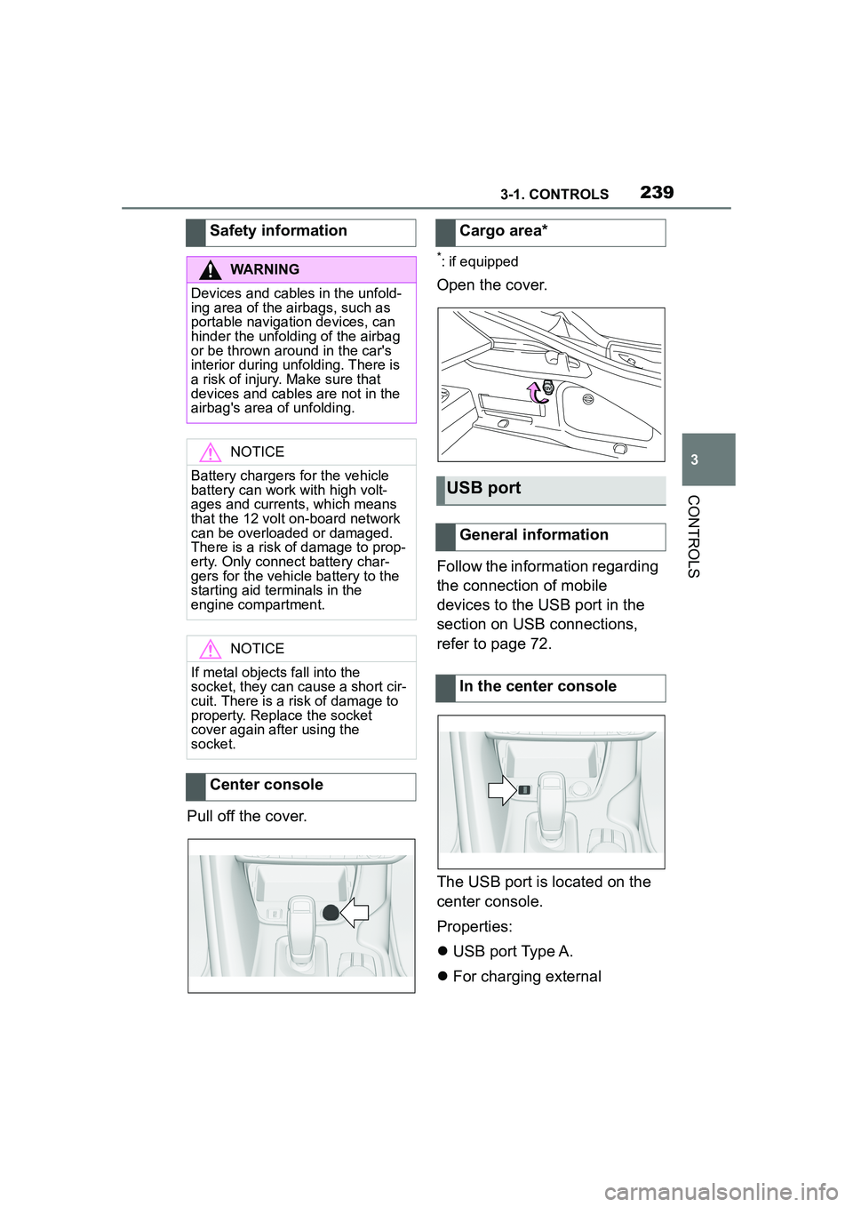
Pull off the cover.
*: if equipped
Open the cover.
Follow the information regarding
the connection of mobile
devices to the USB port in the
section on USB connections,
refer to page 72.
The USB port is located on the
center console.
Properties:
USB port Type A.
For charging external
Safety information
WARNING
Devices and cables in the unfold-
ing area of the airbags, such as
portable navigation devices, can
hinder the unfolding of the airbag
or be thrown around in the car's
interior during unfolding. There is
a risk of injury. Make sure that
devices and cables are not in the
airbag's area of unfolding.
NOTICE
Battery chargers for the vehicle
battery can work with high volt-
ages and currents, which means
that the 12 volt on-board network
can be overloaded or damaged.
There is a risk of damage to prop-
erty. Only connect battery char-
gers for the vehicle battery to the
starting aid terminals in the
engine compartment.
NOTICE
If metal objects fall into the
socket, they can cause a short cir-
cuit. There is a risk of damage to
property. Replace the socket
cover again after using the
socket.
Center console
Cargo area*
USB port
General information
In the center console
Page 240 of 356
2403-1. CONTROLS
devices.
Charging current:
max. 1.5 A (vehicles without wire-
less charger)
max. 2.1 A (vehicles with wireless
charger)
For data transfer.
The wireless charging tray
enables the following functions
to be performed without cables:
Charging the rechargeable
battery of a mobile phone with
Qi capability and of other
mobile devices, which support
the Qi standard.
Connect the mobile phone to
the external antenna.
Depending on the country, this pro-
vides for better network reception
and a consistent reproduction qual-
ity.
When inserting the mobile
phone, make sure there are no
objects between it and the wire-
less charging tray.
During charging, the surface of
the tray and the mobile phone
may become warm. Higher tem-
peratures may lead to a reduc-
tion in the charge current through the mobile phone, and
in isolated cases the charging
process is paused temporarily.
Follow the relevant instructions
in the mobile phone owner's
manual.
If the vehicle is equipped
with a charge indicator, the Con-
trol Display shows whether a
mobile phone with Qi capability
is being charged.
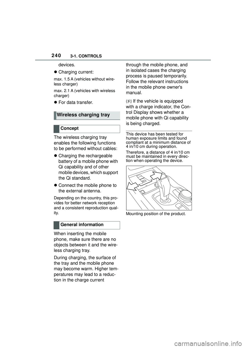
This device has been tested for
human exposure limits and found
compliant at a minimum distance of
4 in/10 cm during operation.
Therefore, a distance of 4 in/10 cm
must be maintained in every direc-
tion when operating the device.
Mounting position of the product.
Wireless charging tray
Concept
General information