cooling TOYOTA HIGHLANDER HYBRID 2008 XU40 / 2.G Owners Manual
[x] Cancel search | Manufacturer: TOYOTA, Model Year: 2008, Model line: HIGHLANDER HYBRID, Model: TOYOTA HIGHLANDER HYBRID 2008 XU40 / 2.GPages: 580, PDF Size: 13.29 MB
Page 32 of 580
32 1-1. Hybrid system
●To help prevent the 12-volt battery from becoming discharged, drive the
vehicle at least once a month, and operate the accessories only when
the “READY” indicator is on. When parking the vehicle, make sure the
doors is closed and all lights are turned off.
■ After the 12-volt battery has di scharged or has been changed or
removed
The gasoline engine may not stop even if the vehicle is running on the hybrid
battery (traction battery). If this continues for a few days, contact your Toyota
dealer.
■ Sounds and vibrations specific to a hybrid vehicle
There may be no engine sounds or vibration even though the vehicle is able
to move. Always put the shift lever in P when parked.
The following sounds or vibrations may occur when the hybrid system is
operating, and are not a malfunction:
●Motor sounds may be heard from the engine compartment.
● Sounds may be heard from the hybrid battery (traction battery) behind
the rear seat when the hybrid system starts or stops.
● Sounds may be heard from the transaxle when the hybrid system starts
or stops, or while the vehicle is idling.
● Engine sounds may be heard when accelerating sharply.
● Sounds may be heard from the regenerative brake when you press the
brake pedal.
● Vibration may be felt when the gasoline engine starts or stops.
● You may hear cooling fan sounds coming from the air intake vents below
the second seat.
■ Maintenance, repair, recycling, and disposal
Contact your Toyota dealer regarding maintenance, repair, recycling and
disposal. Do not dispose of the vehicle yourself.
Page 34 of 580
34 1-1. Hybrid system
■Hybrid battery air vent
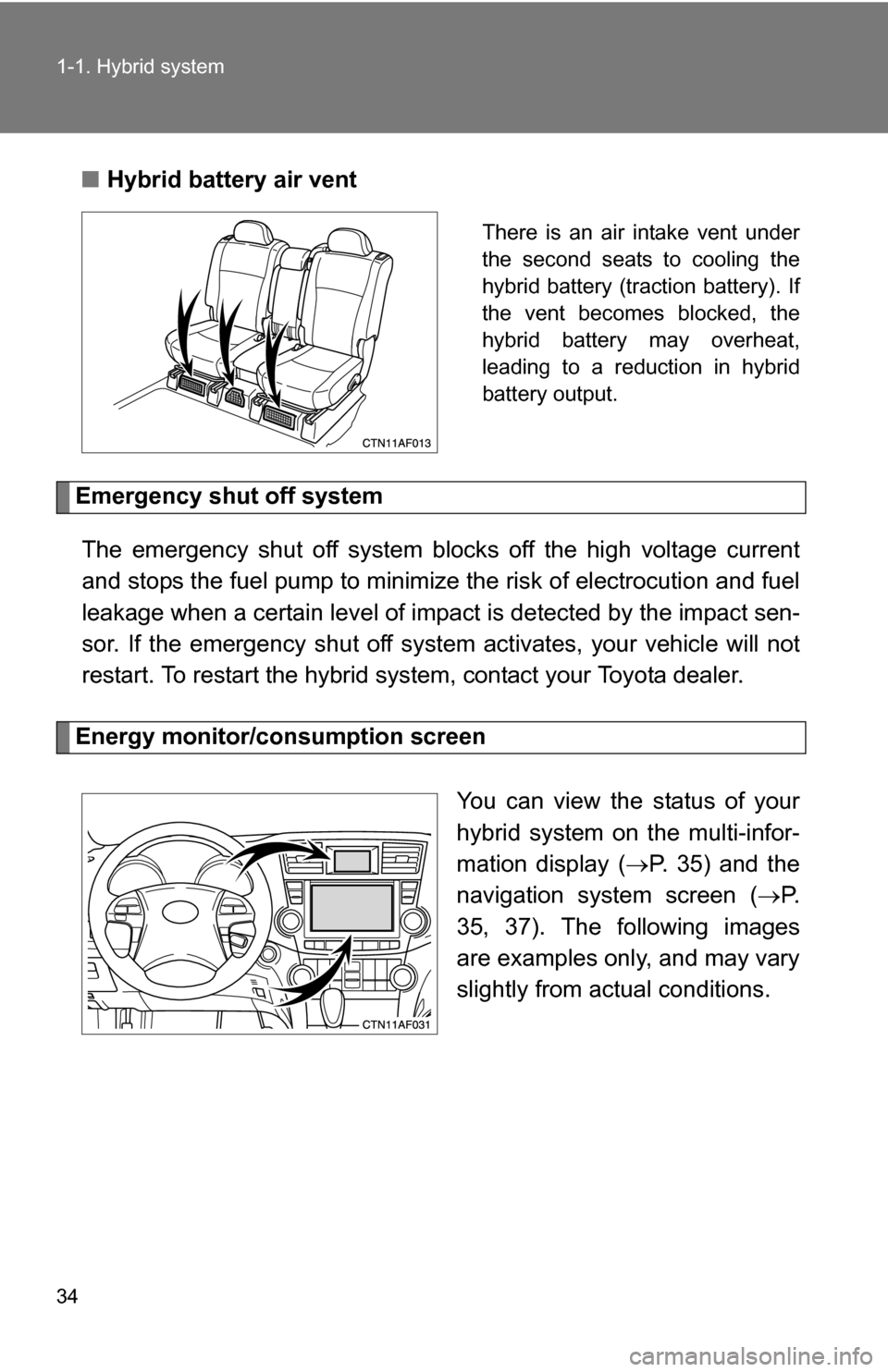
There is an air intake vent under
the second seats to cooling the
hybrid battery (traction battery). If
the vent becomes blocked, the
hybrid battery may overheat,
leading to a reduction in hybrid
battery output.
Emergency shut off system
The emergency shut off system blocks off the high voltage current
and stops the fuel pump to minimize the risk of electrocution and fuel
leakage when a certain level of impact is detected by the impact sen-
sor. If the emergency shut off syste m activates, your vehicle will not
restart. To restart the hybrid system, contact your Toyota dealer.
Energy monitor/consumption screen
You can view the status of your
hybrid system on the multi-infor-
mation display (P. 35) and the
navigation system screen ( P.
35, 37). The following images
are examples only, and may vary
slightly from actual conditions.
Page 248 of 580
248
3-1. Using the air conditioning system and defogger
Front manual air conditioning system (if equipped)
Adjusting the settings
■ Adjusting the temperature setting
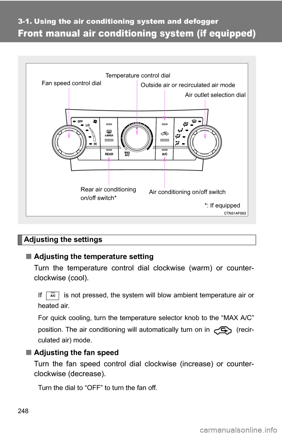
Turn the temperature control dial clockwise (warm) or counter-
clockwise (cool).
If is not pressed, the system will blow ambient temperature air or
heated air.
For quick cooling, turn the temperature selector knob to the “MAX A/C”
position. The air conditioning will automatically turn on in (recir-
culated air) mode.
■ Adjusting the fan speed
Turn the fan speed control dial clockwise (increase) or counter-
clockwise (decrease).
Turn the dial to “OFF” to turn the fan off.
Fan speed control dial
Air outlet selection dial
Air conditioning on/off switch
Temperature control dial
Outside air or recirculated air mode
Rear air conditioning
on/off switch*
*: If equipped
Page 418 of 580
418 4-3. Do-it-yourself maintenance
CAUTION
The engine compartment contains many mechanisms and fluids that may
move suddenly, become hot, or become electrically energized. To avoid death
or serious injury observe the following precautions.
■When working on the engine compartment
●Make sure that the indicator on the “POWER” switch and the “READY”
indicator are both off.
● Keep hands, clothing, and tools away from the moving fan.
● Be careful not to touch the engine, power control unit, radiator, exhaust
manifold, etc. right after driving as they may be hot. Oil and other fluids
may also be hot.
● Do not leave anything that may burn easily, such as paper or rags, in the
engine compartment.
● Do not smoke, cause sparks or expose an open flame to fuel or the bat-
tery. Fuel and battery fumes are flammable.
● Be extremely cautious when working on the battery. It contains poisonous
and corrosive sulfuric acid.
● Never touch, disassemble, remove or replace the high voltage parts,
cables and their connectors. It can cause severe burns or electric shock
that may result in death or serious injury.
● Take care because brake fluid can harm your hands or eyes and damage
painted surfaces.
If fluid gets on your hands or in your eyes, flush the affected area with
clean water immediately.
If you still experience discomfort, see a doctor.
● Do not touch the engine compartment when the electric cooling fan is
operating.
The electric cooling fan may keep rotating for about 3 minutes even after
the “POWER” switch is OFF.
With the “POWER” switch in ON mode, the electric cooling fan may auto-
matically start to run if the air conditioning is on and/or the coolant temper-
ature is high. Be sure the “POWER” switch is OFF when working near the
electric cooling fan or radiator grille.
Page 424 of 580
424
4-3. Do-it-yourself maintenance
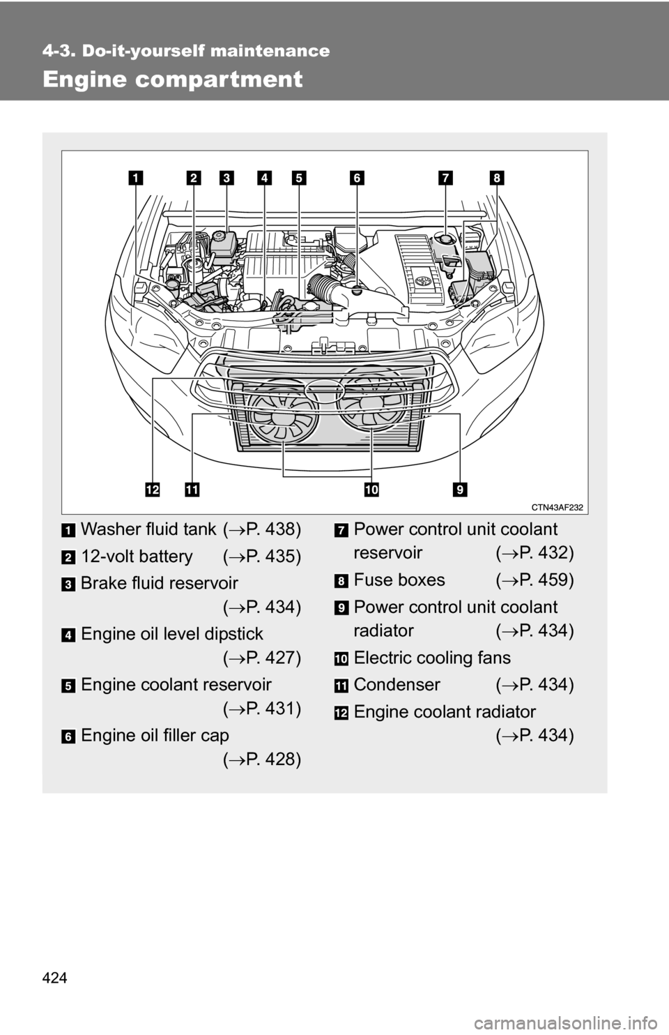
Engine compar tment
Washer fluid tank (P. 438)
12-volt battery ( P. 435)
Brake fluid reservoir ( P. 434)
Engine oil level dipstick ( P. 427)
Engine coolant reservoir ( P. 431)
Engine oil filler cap ( P. 428)Power control unit coolant
reservoir ( P. 432)
Fuse boxes ( P. 459)
Power control unit coolant
radiator ( P. 434)
Electric cooling fans
Condenser ( P. 434)
Engine coolant radiator ( P. 434)
Page 432 of 580
432 4-3. Do-it-yourself maintenance
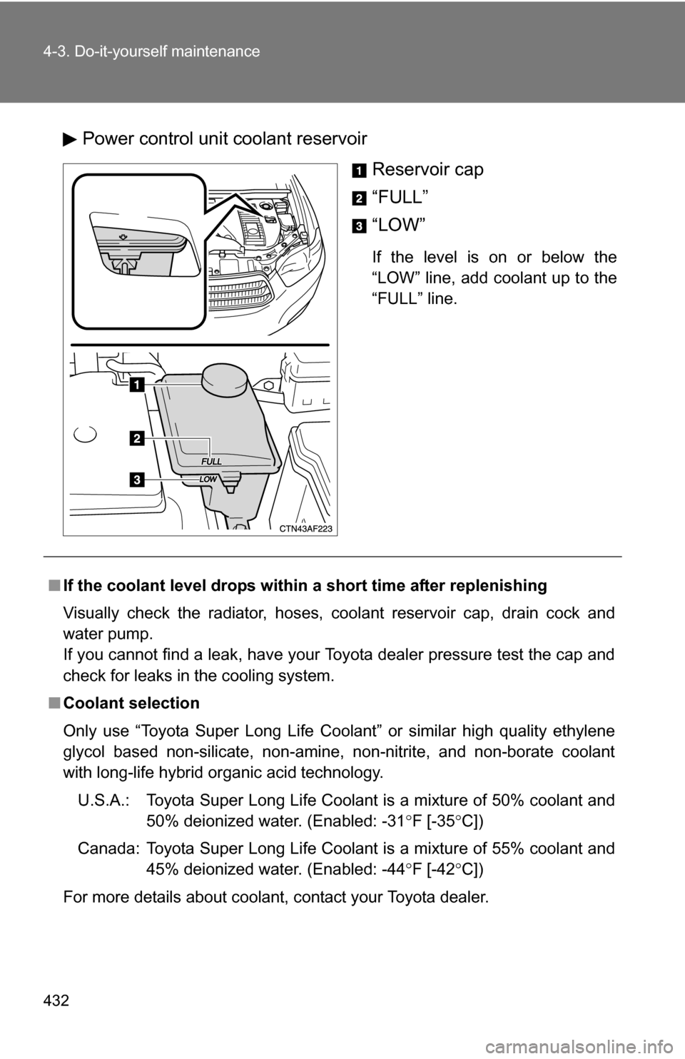
Power control unit coolant reservoirReservoir cap
“FULL”
“LOW”
If the level is on or below the
“LOW” line, add coolant up to the
“FULL” line.
■If the coolant level drops within a short time after replenishing
Visually check the radiator, hoses, coolant reservoir cap, drain cock and
water pump.
If you cannot find a leak, have your Toyota dealer pressure test the cap and
check for leaks in the cooling system.
■ Coolant selection
Only use “Toyota Super Long Life Coolant” or similar high quality ethylene
glycol based non-silicate, non-amine, non-nitrite, and non-borate coolant
with long-life hybrid organic acid technology.
U.S.A.: Toyota Super Long Life Coolant is a mixture of 50% coolant and 50% deionized water. (Enabled: -31 F [-35 C])
Canada: Toyota Super Long Life Coolant is a mixture of 55% coolant and 45% deionized water. (Enabled: -44 F [-42 C])
For more details about coolant, contact your Toyota dealer.
Page 433 of 580
433
4-3. Do-it-yourself maintenance
4
Maintenance and care
CAUTION
■
When the hybrid system is hot
Do not remove the coolant reservoir cap.
The cooling system may be under pressure and may spray hot coolant if the
cap is removed, causing burns or other injuries.
NOTICE
■When adding coolant
Coolant is neither plain water nor stra ight antifreeze. The correct mixture of
water and antifreeze must be used to provide proper lubrication, corrosion
protection and cooling. Be sure to read the antifreeze or coolant label.
■ If you spill coolant
Be sure to wash it off with water to prevent damage to parts or paint.
Page 434 of 580
434 4-3. Do-it-yourself maintenance
Radiator and condenserCheck the radiators and condenser and clear any foreign objects.
If either of the above parts are ex tremely dirty or you are not sure of
their condition, have your vehicl e checked by your Toyota dealer.
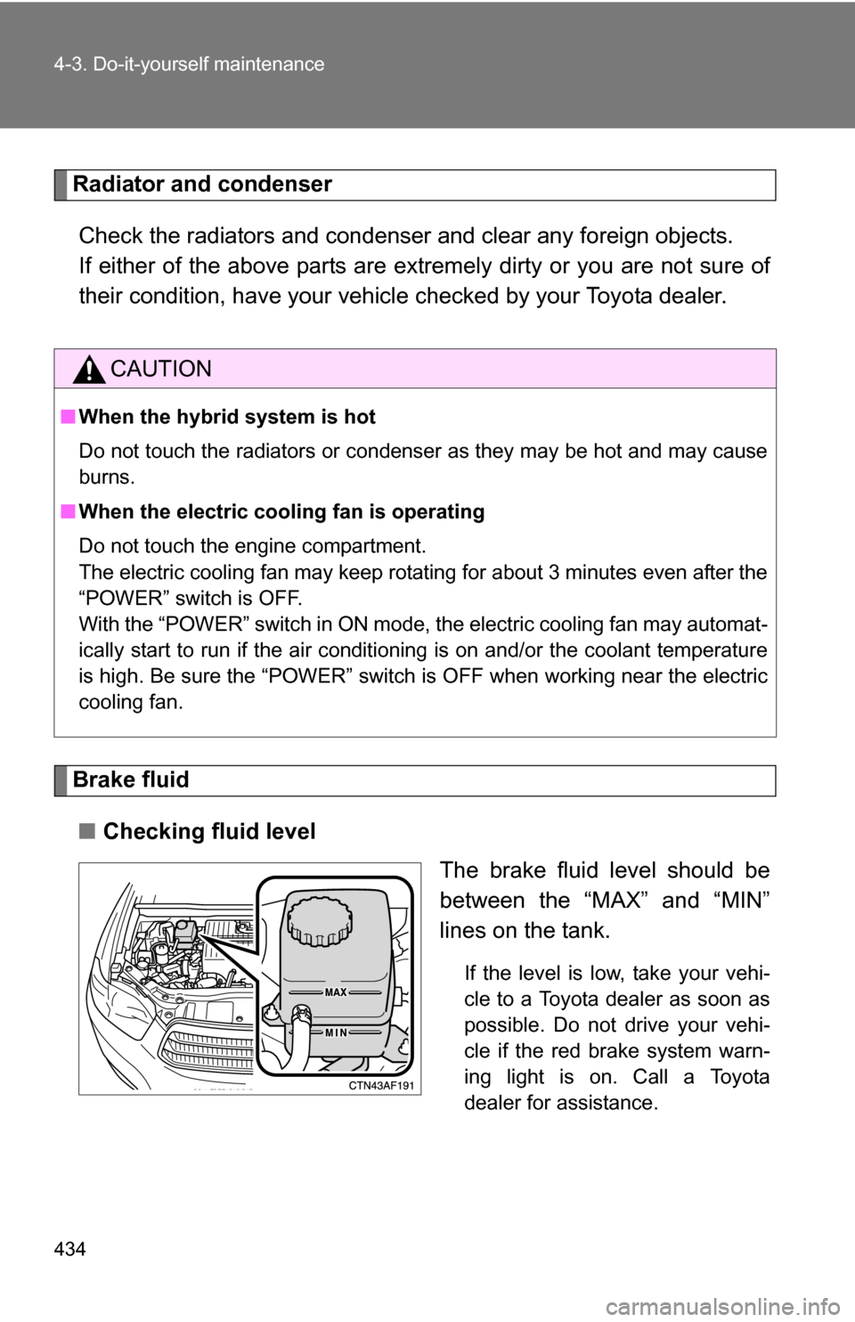
Brake fluid
■ Checking fluid level
The brake fluid level should be
between the “MAX” and “MIN”
lines on the tank.
If the level is low, take your vehi-
cle to a Toyota dealer as soon as
possible. Do not drive your vehi-
cle if the red brake system warn-
ing light is on. Call a Toyota
dealer for assistance.
CAUTION
■When the hybrid system is hot
Do not touch the radiators or condenser as they may be hot and may cause
burns.
■ When the electric cooling fan is operating
Do not touch the engine compartment.
The electric cooling fan may keep rotating for about 3 minutes even after the
“POWER” switch is OFF.
With the “POWER” switch in ON mode, the electric cooling fan may automat-
ically start to run if the air conditioning is on and/or the coolant temperature
is high. Be sure the “POWER” switch is OFF when working near the electric
cooling fan.
Page 463 of 580
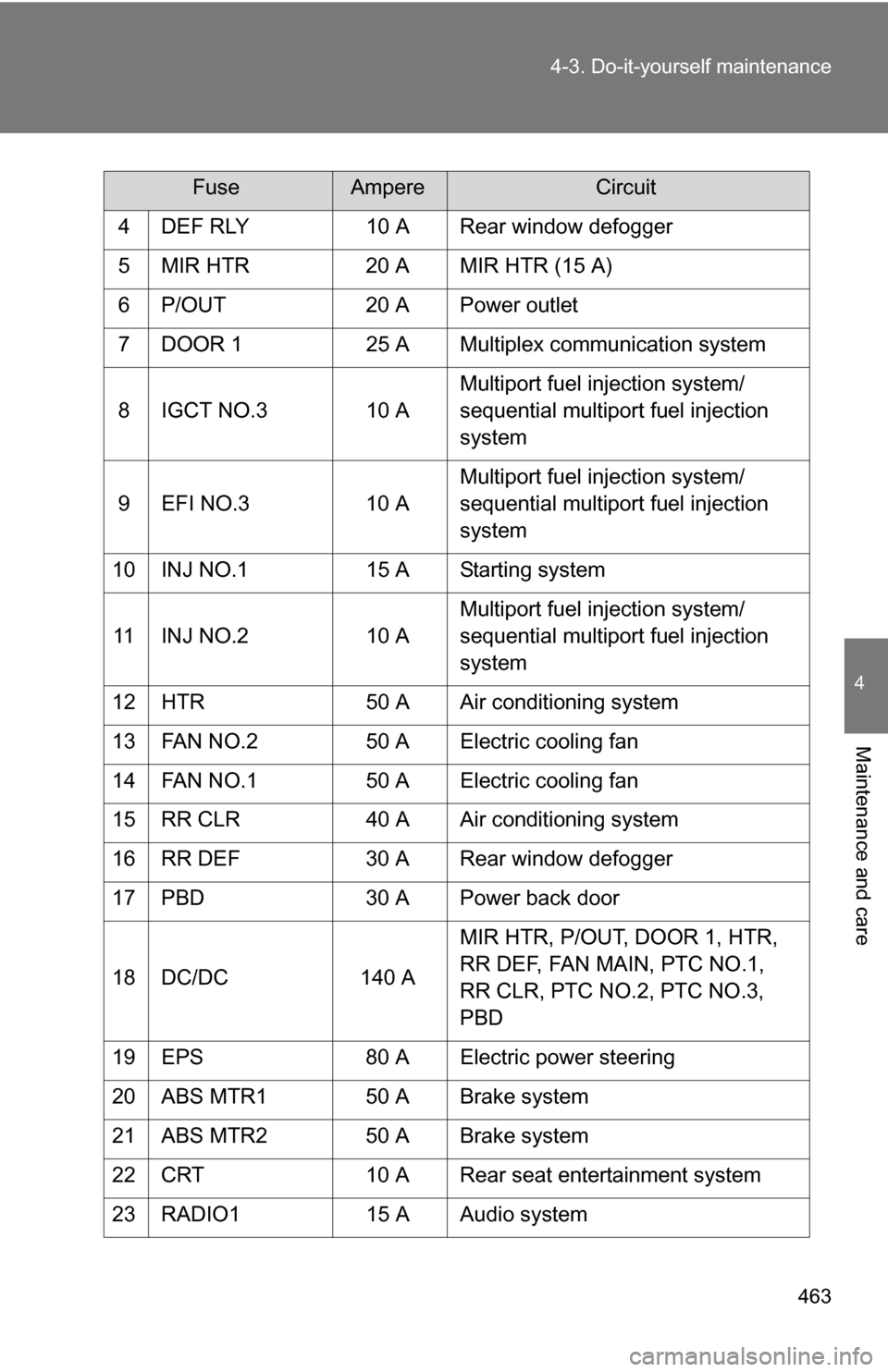
463
4-3. Do-it-yourself maintenance
4
Maintenance and care
4 DEF RLY
10 A Rear window defogger
5 MIR HTR 20 A MIR HTR (15 A)
6 P/OUT 20 A Power outlet
7 DOOR 1 25 A Multiplex communication system
8 IGCT NO.3 10 A Multiport fuel injection system/
sequential multiport fuel injection
system
9 EFI NO.3 10 AMultiport fuel injection system/
sequential multiport fuel injection
system
10 INJ NO.1 15 A Starting system
11 INJ NO.2 10 AMultiport fuel injection system/
sequential multiport fuel injection
system
12 HTR 50 A Air conditioning system
13 FAN NO.2 50 A Electric cooling fan
14 FAN NO.1 50 A Electric cooling fan
15 RR CLR 40 A Air conditioning system
16 RR DEF 30 A Rear window defogger
17 PBD 30 A Power back door
18 DC/DC 140 AMIR HTR, P/OUT, DOOR 1, HTR,
RR DEF, FAN MAIN, PTC NO.1,
RR CLR, PTC NO.2, PTC NO.3,
PBD
19 EPS 80 A Electric power steering
20 ABS MTR1 50 A Brake system
21 ABS MTR2 50 A Brake system
22 CRT 10 A Rear seat entertainment system
23 RADIO1 15 A Audio system
FuseAmpereCircuit
Page 464 of 580
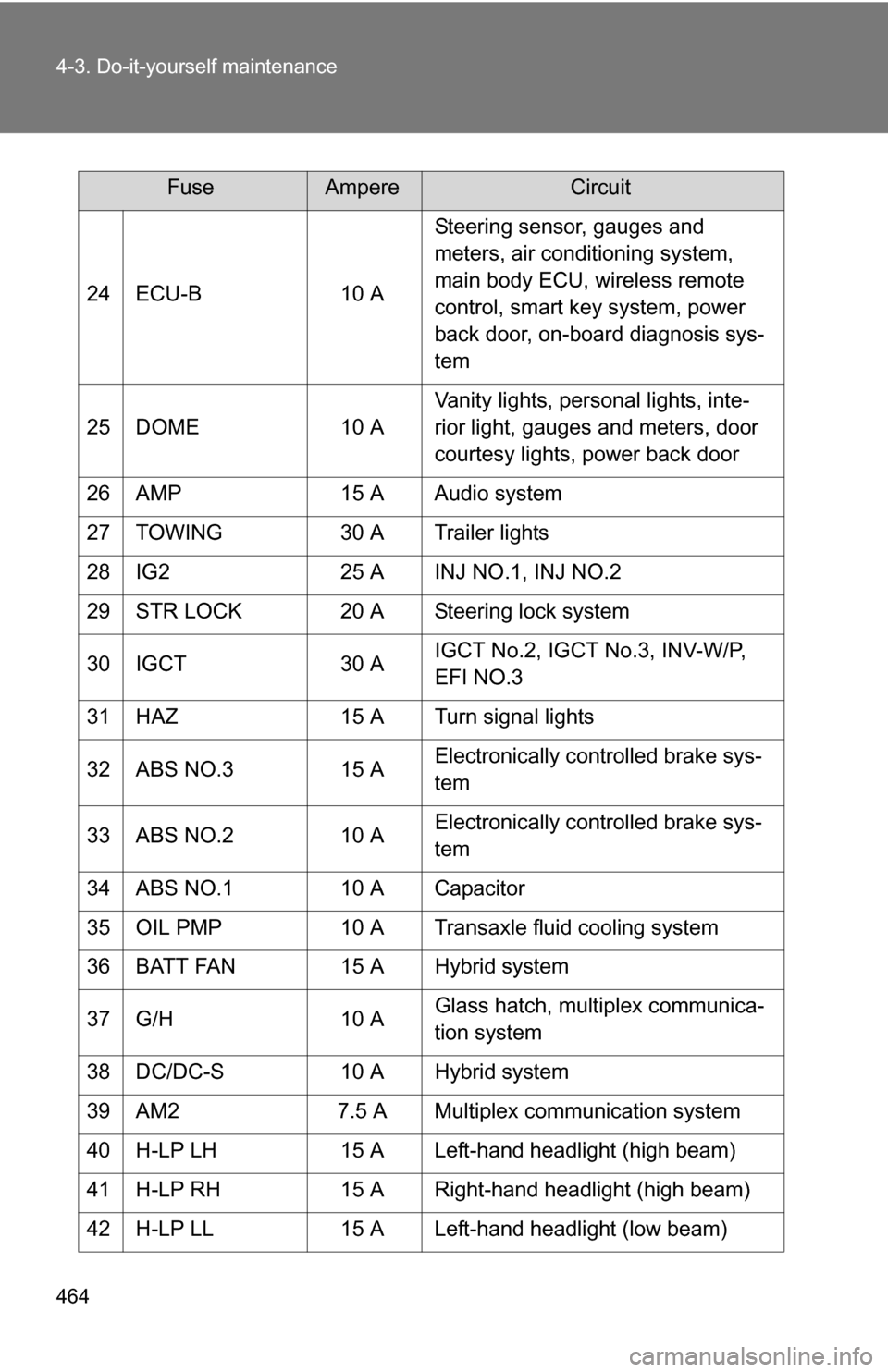
464 4-3. Do-it-yourself maintenance
24 ECU-B10 ASteering sensor, gauges and
meters, air conditioning system,
main body ECU, wireless remote
control, smart key system, power
back door, on-board diagnosis sys-
tem
25 DOME 10 AVanity lights, personal lights, inte-
rior light, gauges and meters, door
courtesy lights, power back door
26 AMP 15 A Audio system
27 TOWING 30 A Trailer lights
28 IG2 25 A INJ NO.1, INJ NO.2
29 STR LOCK 20 A Steering lock system
30 IGCT 30 AIGCT No.2, IGCT No.3, INV-W/P,
EFI NO.3
31 HAZ 15 A Turn signal lights
32 ABS NO.3 15 AElectronically controlled brake sys-
tem
33 ABS NO.2 10 AElectronically controlled brake sys-
tem
34 ABS NO.1 10 A Capacitor
35 OIL PMP 10 A Transaxle fluid cooling system
36 BATT FAN 15 A Hybrid system
37 G/H 10 AGlass hatch, multiplex communica-
tion system
38 DC/DC-S 10 A Hybrid system
39 AM2 7.5 A Multiplex communication system
40 H-LP LH 15 A Left-hand headlight (high beam)
41 H-LP RH 15 A Right-hand headlight (high beam)
42 H-LP LL 15 A Left-hand headlight (low beam)
FuseAmpereCircuit