turn signal TOYOTA HIGHLANDER HYBRID 2021 (in English) User Guide
[x] Cancel search | Manufacturer: TOYOTA, Model Year: 2021, Model line: HIGHLANDER HYBRID, Model: TOYOTA HIGHLANDER HYBRID 2021Pages: 578, PDF Size: 16.92 MB
Page 254 of 578
2544-5. Using the driving support systems
HIGHLANDER HV_UWhile the pre-collision warning function is operating,
if the steering wheel is
operated heavily or suddenly, the pre-collision warning may be cancelled.
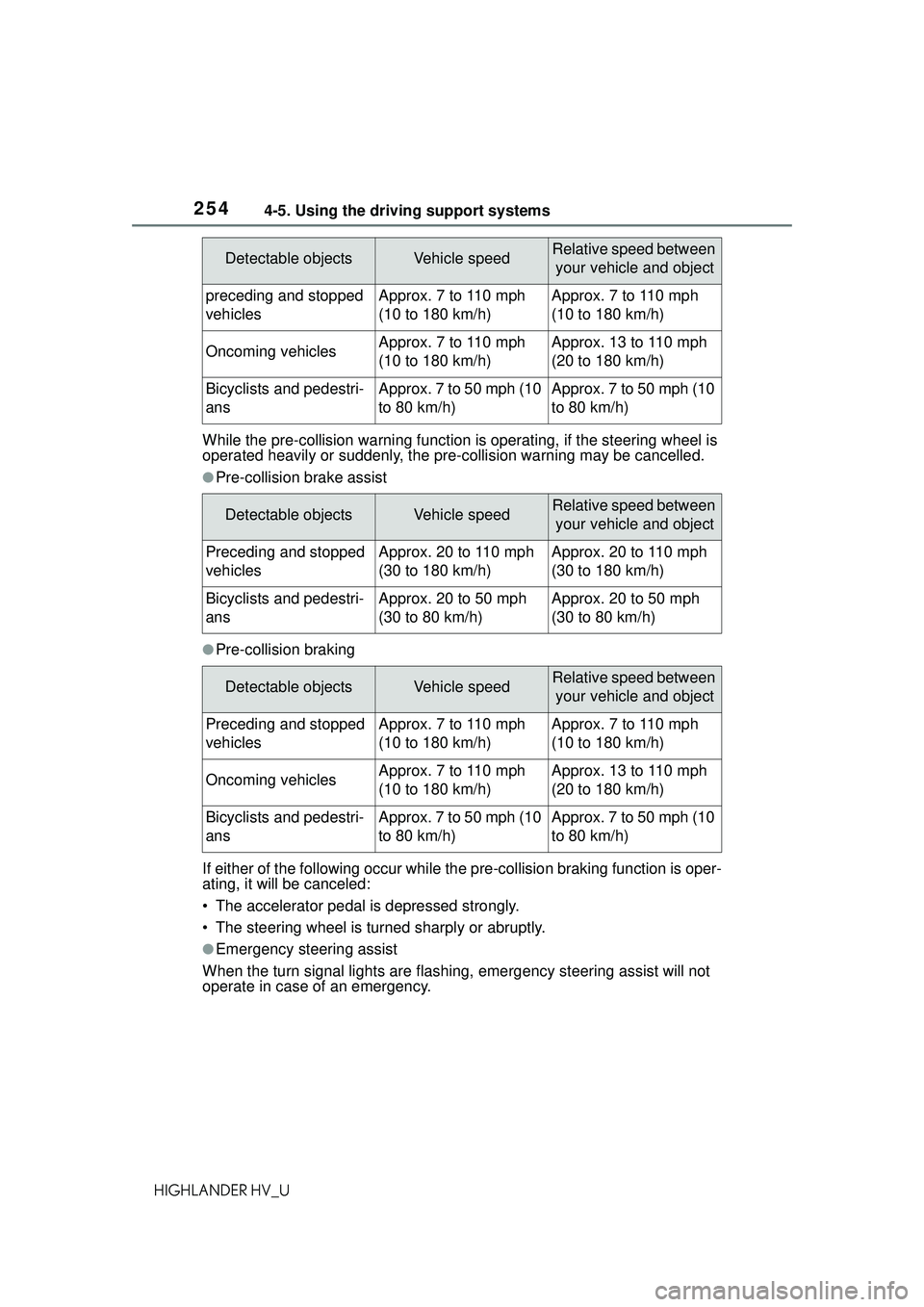
●Pre-collision brake assist
●Pre-collision braking
If either of the following occur while th e pre-collision braking function is oper-
ating, it will be canceled:
• The accelerator pedal is depressed strongly.
• The steering wheel is turned sharply or abruptly.
●Emergency steering assist
When the turn signal lights are flashing, emergency steering assist will not
operate in case of an emergency.
Detectable objectsVehicle speedRelative speed between
your vehicle and object
preceding and stopped
vehiclesApprox. 7 to 110 mph
(10 to 180 km/h)Approx. 7 to 110 mph
(10 to 180 km/h)
Oncoming vehiclesApprox. 7 to 110 mph
(10 to 180 km/h)Approx. 13 to 110 mph
(20 to 180 km/h)
Bicyclists and pedestri-
ansApprox. 7 to 50 mph (10
to 80 km/h)Approx. 7 to 50 mph (10
to 80 km/h)
Detectable objectsVehicle speedRelative speed between your vehicle and object
Preceding and stopped
vehiclesApprox. 20 to 110 mph
(30 to 180 km/h)Approx. 20 to 110 mph
(30 to 180 km/h)
Bicyclists and pedestri-
ansApprox. 20 to 50 mph
(30 to 80 km/h)Approx. 20 to 50 mph
(30 to 80 km/h)
Detectable objectsVehicle speedRelative speed between your vehicle and object
Preceding and stopped
vehiclesApprox. 7 to 110 mph
(10 to 180 km/h)Approx. 7 to 110 mph
(10 to 180 km/h)
Oncoming vehiclesApprox. 7 to 110 mph
(10 to 180 km/h)Approx. 13 to 110 mph
(20 to 180 km/h)
Bicyclists and pedestri-
ansApprox. 7 to 50 mph (10
to 80 km/h)Approx. 7 to 50 mph (10
to 80 km/h)
Page 255 of 578
2554-5. Using the driving support systems
4
Driving
HIGHLANDER HV_UIf any of the following occur while the
emergency steering assist function is
operating, it will be canceled:
• The accelerator pedal is depressed strongly.
• The steering wheel is turned sharply or abruptly.
• The brake pedal is depressed.
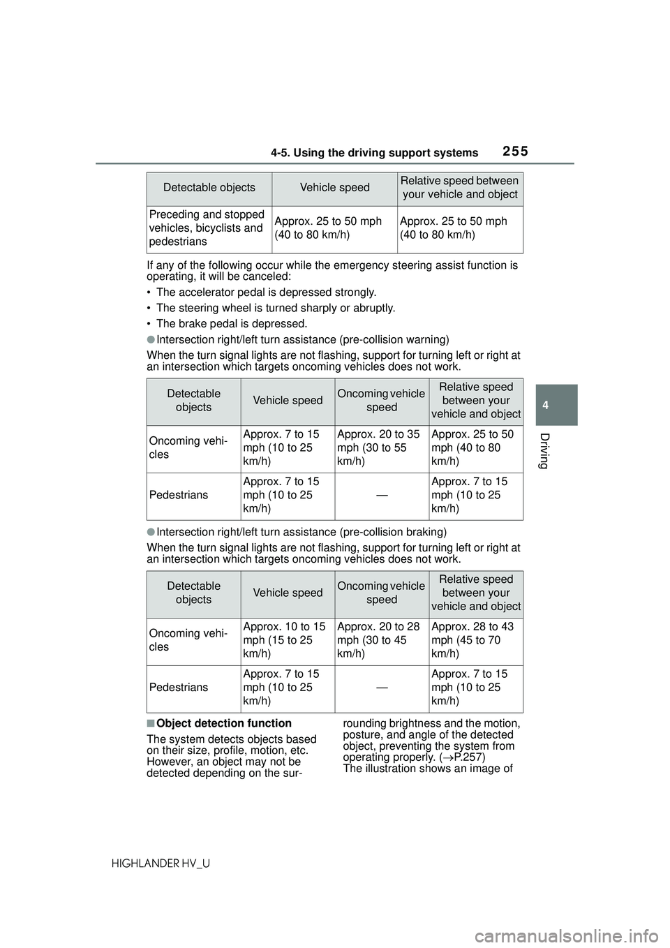
●Intersection right/left turn assistance (pre-collision warning)
When the turn signal lights are not flashing, support for turning left or right at
an intersection which targets onco ming vehicles does not work.
●Intersection right/left turn assistance (pre-collision braking)
When the turn signal lights are not flashing, support for turning left or right at
an intersection which targets onco ming vehicles does not work.
■Object detection function
The system detects objects based
on their size, profile, motion, etc.
However, an object may not be
detected depending on the sur- rounding brightness and the motion,
posture, and angle of the detected
object, preventing the system from
operating properly. (
P.257)
The illustration sh ows an image of
Detectable objectsVehicle speedRelative speed between
your vehicle and object
Preceding and stopped
vehicles, bicyclists and
pedestriansApprox. 25 to 50 mph
(40 to 80 km/h)Approx. 25 to 50 mph
(40 to 80 km/h)
Detectable objectsVehicle speedOncoming vehicle speedRelative speed between your
vehicle and object
Oncoming vehi-
clesApprox. 7 to 15
mph (10 to 25
km/h)Approx. 20 to 35
mph (30 to 55
km/h)Approx. 25 to 50
mph (40 to 80
km/h)
Pedestrians
Approx. 7 to 15
mph (10 to 25
km/h)
—
Approx. 7 to 15
mph (10 to 25
km/h)
Detectable objectsVehicle speedOncoming vehicle speedRelative speed between your
vehicle and object
Oncoming vehi-
clesApprox. 10 to 15
mph (15 to 25
km/h)Approx. 20 to 28
mph (30 to 45
km/h)Approx. 28 to 43
mph (45 to 70
km/h)
Pedestrians
Approx. 7 to 15
mph (10 to 25
km/h)
—
Approx. 7 to 15
mph (10 to 25
km/h)
Page 264 of 578
2644-5. Using the driving support systems
HIGHLANDER HV_U
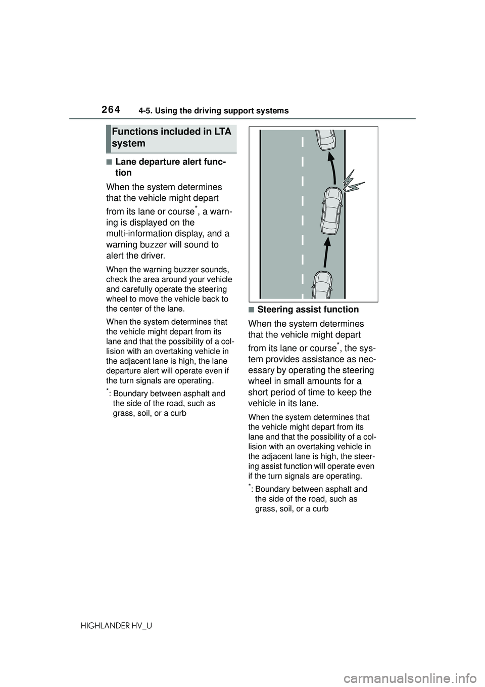
■Lane departure alert func-
tion
When the system determines
that the vehicle might depart
from its lane or course
*, a warn-
ing is displayed on the
multi-information display, and a
warning buzzer will sound to
alert the driver.
When the warning buzzer sounds,
check the area around your vehicle
and carefully operate the steering
wheel to move the vehicle back to
the center of the lane.
When the system de termines that
the vehicle might depart from its
lane and that the possibility of a col-
lision with an overtaking vehicle in
the adjacent lane is high, the lane
departure alert will operate even if
the turn signals are operating.
*: Boundary between asphalt and the side of the road, such as
grass, soil, or a curb
■Steering assist function
When the system determines
that the vehicle might depart
from its lane or course
*, the sys-
tem provides assistance as nec-
essary by operating the steering
wheel in small amounts for a
short period of time to keep the
vehicle in its lane.
When the system determines that
the vehicle might depart from its
lane and that the possibility of a col-
lision with an overtaking vehicle in
the adjacent lane is high, the steer-
ing assist function will operate even
if the turn signals are operating.
*: Boundary between asphalt and the side of the road, such as
grass, soil, or a curb
Functions included in LTA
system
Page 268 of 578
2684-5. Using the driving support systems
HIGHLANDER HV_Udisplay.
Indicates that steering assist of the
lane centering function is operating
by monitoring the position of a pre-
ceding vehicle.
When the follow-up cruising display
is displayed, if the preceding vehi-
cle moves, your vehicle may move
in the same way. Always pay care-
ful attention to your surroundings
and operate the steering wheel as
necessary to correct the path of the
vehicle and ensure safety.
■Operation conditions of each
function
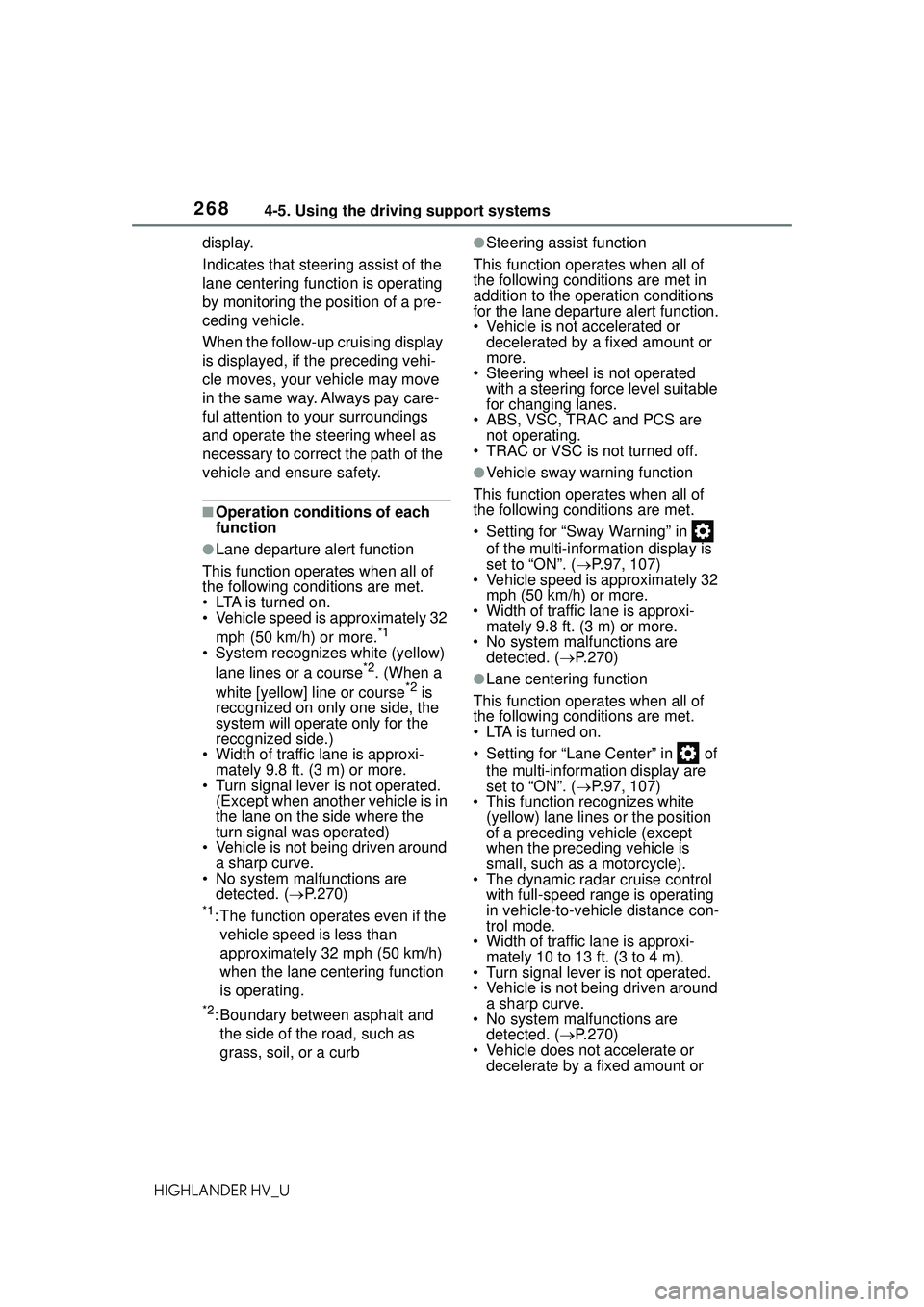
●Lane departure alert function
This function operates when all of
the following conditions are met.
• LTA is turned on.
• Vehicle speed is approximately 32 mph (50 km/h) or more.
*1
• System recognizes white (yellow) lane lines or a course*2. (When a
white [yellow] line or course*2 is
recognized on only one side, the
system will operate only for the
recognized side.)
• Width of traffic lane is approxi- mately 9.8 ft. (3 m) or more.
• Turn signal lever is not operated. (Except when another vehicle is in
the lane on the side where the
turn signal was operated)
• Vehicle is not being driven around a sharp curve.
• No system malfunctions are
detected. ( P.270)
*1: The function operates even if the
vehicle speed is less than
approximately 32 mph (50 km/h)
when the lane centering function
is operating.
*2: Boundary between asphalt and the side of the road, such as
grass, soil, or a curb
●Steering assist function
This function operates when all of
the following conditions are met in
addition to the operation conditions
for the lane departure alert function.
• Vehicle is not accelerated or decelerated by a fixed amount or
more.
• Steering wheel is not operated with a steering force level suitable
for changing lanes.
• ABS, VSC, TRAC and PCS are not operating.
• TRAC or VSC is not turned off.
●Vehicle sway warning function
This function operates when all of
the following conditions are met.
• Setting for “Sway Warning” in of the multi-information display is
set to “ON”. ( P.97, 107)
• Vehicle speed is approximately 32 mph (50 km/h) or more.
• Width of traffic lane is approxi- mately 9.8 ft. (3 m) or more.
• No system malfunctions are
detected. ( P.270)
●Lane centering function
This function operates when all of
the following conditions are met.
• LTA is turned on.
• Setting for “Lane Center” in of the multi-information display are
set to “ON”. ( P.97, 107)
• This function recognizes white (yellow) lane lines or the position
of a preceding vehicle (except
when the preceding vehicle is
small, such as a motorcycle).
• The dynamic radar cruise control with full-speed range is operating
in vehicle-to-vehicle distance con-
trol mode.
• Width of traffic lane is approxi-
mately 10 to 13 ft. (3 to 4 m).
• Turn signal lever is not operated.
• Vehicle is not being driven around a sharp curve.
• No system malfunctions are detected. ( P.270)
• Vehicle does not accelerate or decelerate by a fixed amount or
Page 275 of 578
2754-5. Using the driving support systems
4
Driving
HIGHLANDER HV_UWhen the turn signal lever is operated and your vehicle moves to an over-
taking lane while driving at 50 mph (
80 km/h) or more, the vehicle will accel-
erate to help to overtake a passing vehicle.
The system’s identification of what is an overtaking lane may be determined
solely based on the location of the steering wheel in the vehicle (left side
driver position versus right side driver position.) If the vehicle is driven to a
region where the overtaking lane is on a different side from where the vehi-
cle is normally driven, the vehicle may accelerate when the turn signal lever
is operated in the opposite direction to the overtaking lane (e.g., if the driver
normally operates the vehicle in a region where the overtaking lane is to the
right but then drives to a region where the overtaking lane is to the left, the
vehicle may accelerate when the ri ght turn signal is activated).
Example of acceleration
When there are no longer any preceding vehicles driving slower
than the set speed
The system accelerates until the set speed is reached. The system then
returns to constant speed cruising.
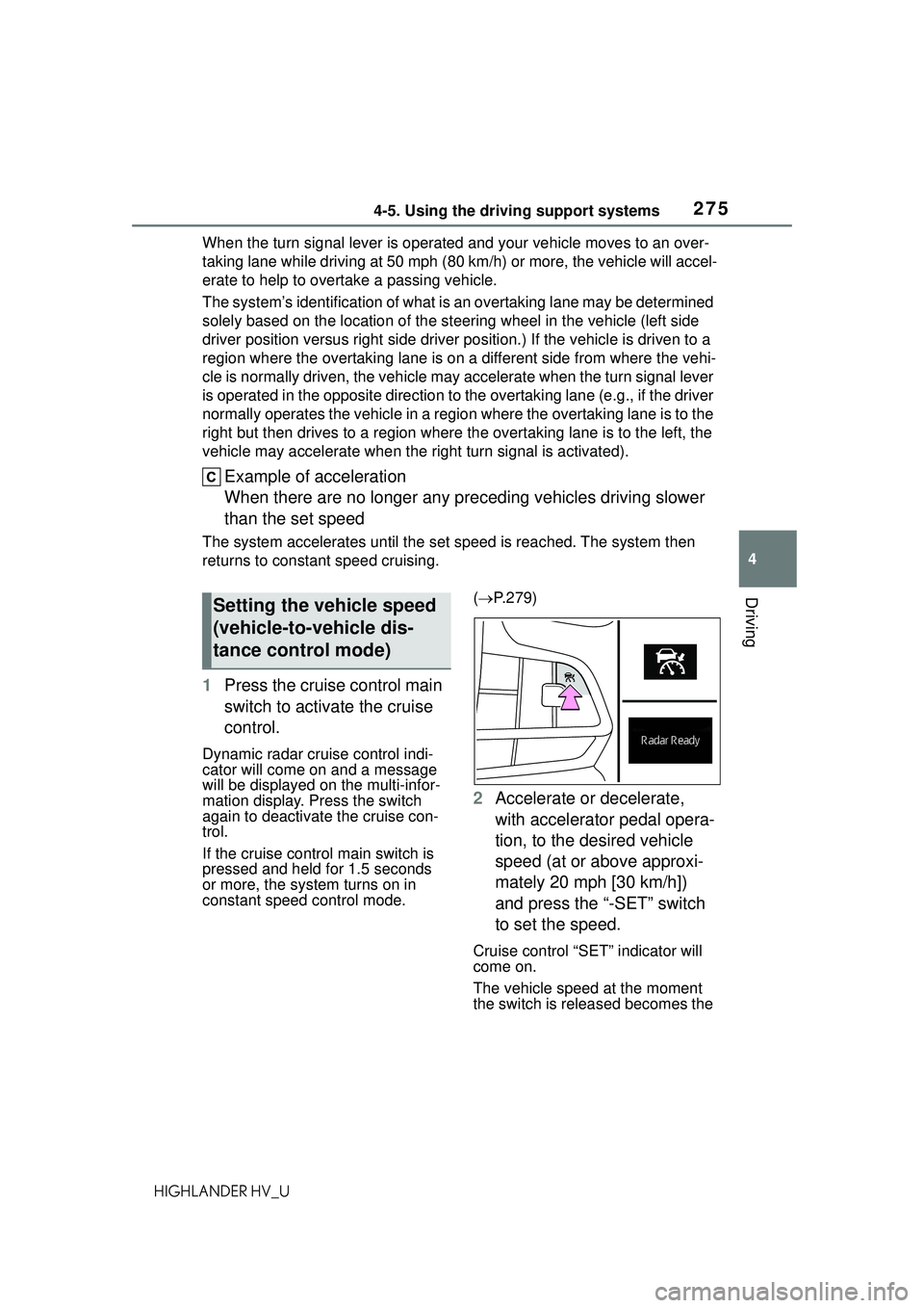
1 Press the cruise control main
switch to activate the cruise
control.
Dynamic radar cruise control indi-
cator will come on and a message
will be displayed on the multi-infor-
mation display. Press the switch
again to deactivate the cruise con-
trol.
If the cruise control main switch is
pressed and held for 1.5 seconds
or more, the system turns on in
constant speed control mode. (
P.279)
2 Accelerate or decelerate,
with accelerator pedal opera-
tion, to the desired vehicle
speed (at or above approxi-
mately 20 mph [30 km/h])
and press the “-SET” switch
to set the speed.
Cruise control “SET” indicator will
come on.
The vehicle speed at the moment
the switch is released becomes the
Setting the vehicle speed
(vehicle-to-vehicle dis-
tance control mode)
Page 286 of 578
2864-5. Using the driving support systems
HIGHLANDER HV_U
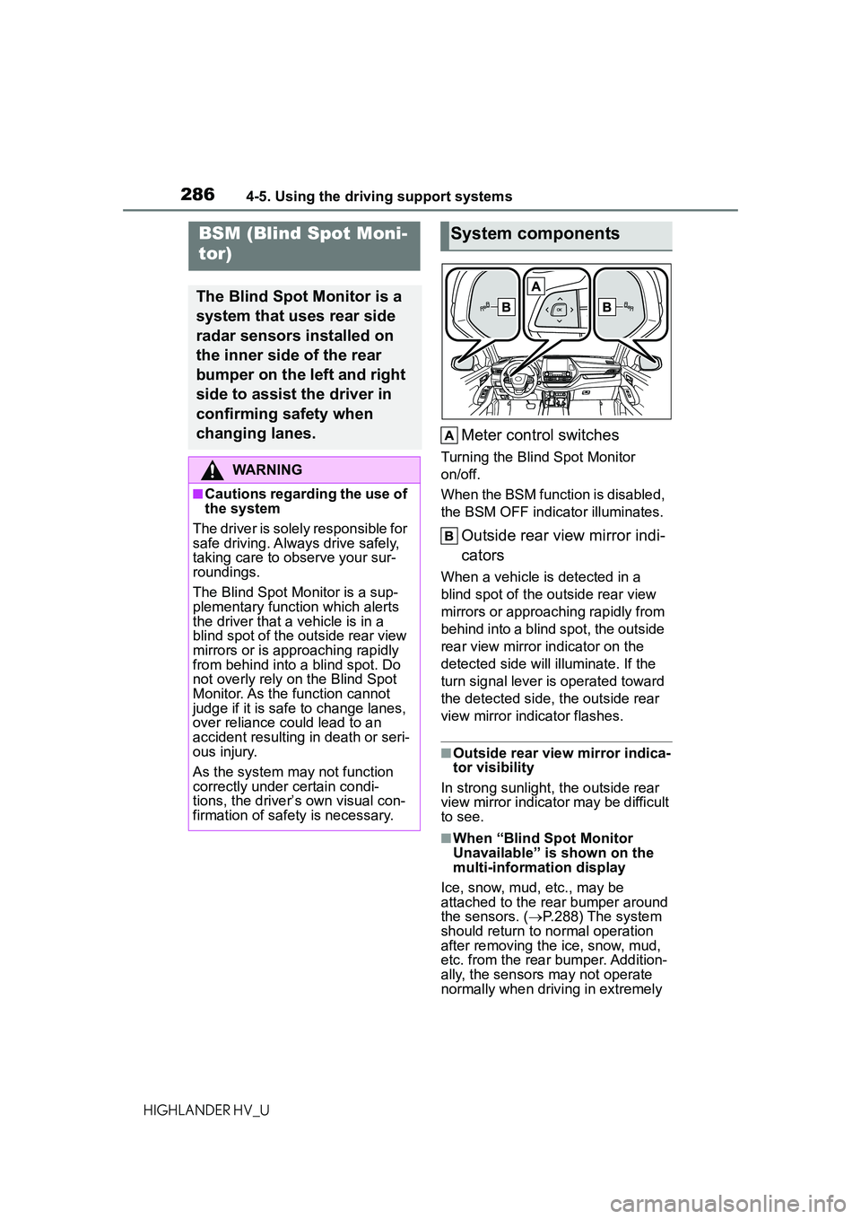
Meter control switches
Turning the Blind Spot Monitor
on/off.
When the BSM function is disabled,
the BSM OFF indicator illuminates.
Outside rear view mirror indi-
cators
When a vehicle is detected in a
blind spot of the outside rear view
mirrors or approaching rapidly from
behind into a blind spot, the outside
rear view mirror indicator on the
detected side will illuminate. If the
turn signal lever is operated toward
the detected side, the outside rear
view mirror indicator flashes.
■Outside rear view mirror indica-
tor visibility
In strong sunlight, the outside rear
view mirror indicator may be difficult
to see.
■When “Blind Spot Monitor
Unavailable” is shown on the
multi-information display
Ice, snow, mud, etc., may be
attached to the rear bumper around
the sensors. ( P.288) The system
should return to normal operation
after removing the ice, snow, mud,
etc. from the rear bumper. Addition-
ally, the sensors may not operate
normally when driving in extremely
BSM (Blind Spot Moni-
tor)
The Blind Spot Monitor is a
system that uses rear side
radar sensors installed on
the inner side of the rear
bumper on the left and right
side to assist the driver in
confirming safety when
changing lanes.
WARNING
■Cautions regarding the use of
the system
The driver is solely responsible for
safe driving. A lways drive safely,
taking care to observe your sur-
roundings.
The Blind Spot Monitor is a sup-
plementary function which alerts
the driver that a vehicle is in a
blind spot of the outside rear view
mirrors or is approaching rapidly
from behind into a blind spot. Do
not overly rely on the Blind Spot
Monitor. As the function cannot
judge if it is safe to change lanes,
over reliance could lead to an
accident resulting in death or seri-
ous injury.
As the system may not function
correctly under certain condi-
tions, the driver’s own visual con-
firmation of safety is necessary.
System components
Page 449 of 578
4496-3. Do-it-yourself maintenance
6
Maintenance and care
HIGHLANDER HV_U
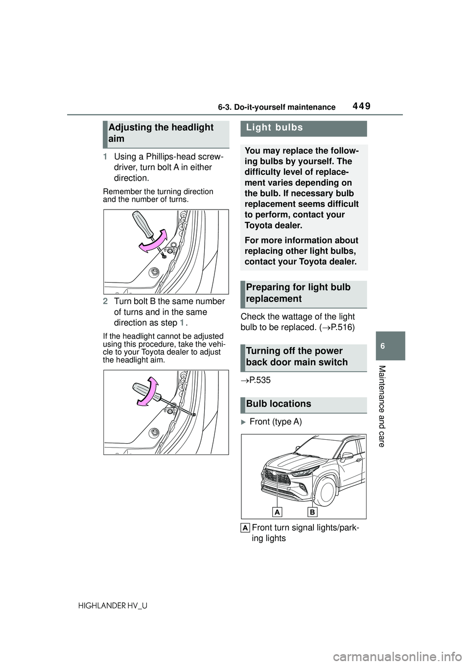
1Using a Phillips-head screw-
driver, turn bolt A in either
direction.
Remember the turning direction
and the number of turns.
2Turn bolt B the same number
of turns and in the same
direction as step 1.
If the headlight cannot be adjusted
using this procedure, take the vehi-
cle to your Toyota dealer to adjust
the headlight aim.
Check the wattage of the light
bulb to be replaced. ( P.516)
P.535
Front (type A)
Front turn signal lights/park-
ing lights
Adjusting the headlight
aimLight bulbs
You may replace the follow-
ing bulbs by yourself. The
difficulty level of replace-
ment varies depending on
the bulb. If necessary bulb
replacement seems difficult
to perform, contact your
Toyota dealer.
For more information about
replacing other light bulbs,
contact your Toyota dealer.
Preparing for light bulb
replacement
Turning off the power
back door main switch
Bulb locations
Page 450 of 578
4506-3. Do-it-yourself maintenance
HIGHLANDER HV_U
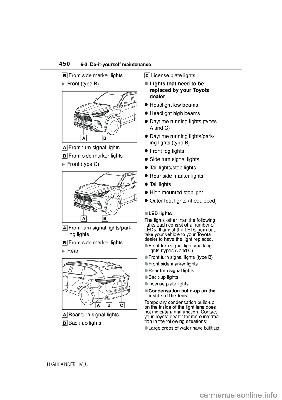
Front side marker lights
Front (type B)Front turn signal lights
Front side marker lights
Front (type C)Front turn signal lights/park-
ing lights
Front side marker lights
RearRear turn signal lights
Back-up lights License plate lights
■Lights that need to be
replaced by your Toyota
dealer
Headlight low beams
Headlight high beams
Daytime running lights (types
A and C)
Daytime running lights/park-
ing lights (type B)
Front fog lights
Side turn signal lights
Tail lights/stop lights
Rear side marker lights
Tail lights
High mounted stoplight
Outer foot lights (if equipped)
■LED lights
The lights other than the following
lights each consist of a number of
LEDs. If any of the LEDs burn out,
take your vehicle to your Toyota
dealer to have the light replaced.
●Front turn signal lights/parking
lights (types A and C)
●Front turn signal lights (type B)
●Front side marker lights
●Rear turn signal lights
●Back-up lights
●License plate lights
■Condensation build-up on the
inside of the lens
Temporary condensation build-up
on the inside of the light lens does
not indicate a malfunction. Contact
your Toyota dealer for more informa-
tion in the following situations:
●Large drops of water have built up
Page 451 of 578
4516-3. Do-it-yourself maintenance
6
Maintenance and care
HIGHLANDER HV_Uon the inside of the lens.
●Water has built up inside the light.
■When replacing light bulbs
P. 4 4 7
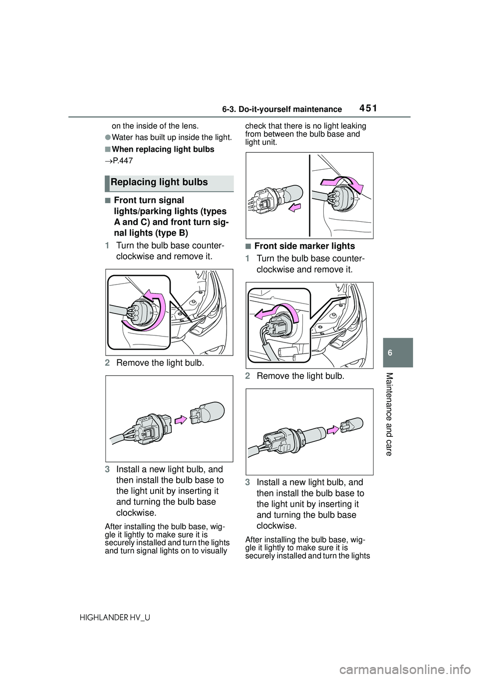
■Front turn signal
lights/parking lights (types
A and C) and front turn sig-
nal lights (type B)
1 Turn the bulb base counter-
clockwise and remove it.
2 Remove the light bulb.
3 Install a new light bulb, and
then install the bulb base to
the light unit by inserting it
and turning the bulb base
clockwise.
After installing the bulb base, wig-
gle it lightly to make sure it is
securely installed and turn the lights
and turn signal lights on to visually check that there is no light leaking
from between the bulb base and
light unit.
■Front side marker lights
1 Turn the bulb base counter-
clockwise and remove it.
2 Remove the light bulb.
3 Install a new light bulb, and
then install the bulb base to
the light unit by inserting it
and turning the bulb base
clockwise.
After installing the bulb base, wig-
gle it lightly to make sure it is
securely installed and turn the lights
Replacing light bulbs
Page 452 of 578
4526-3. Do-it-yourself maintenance
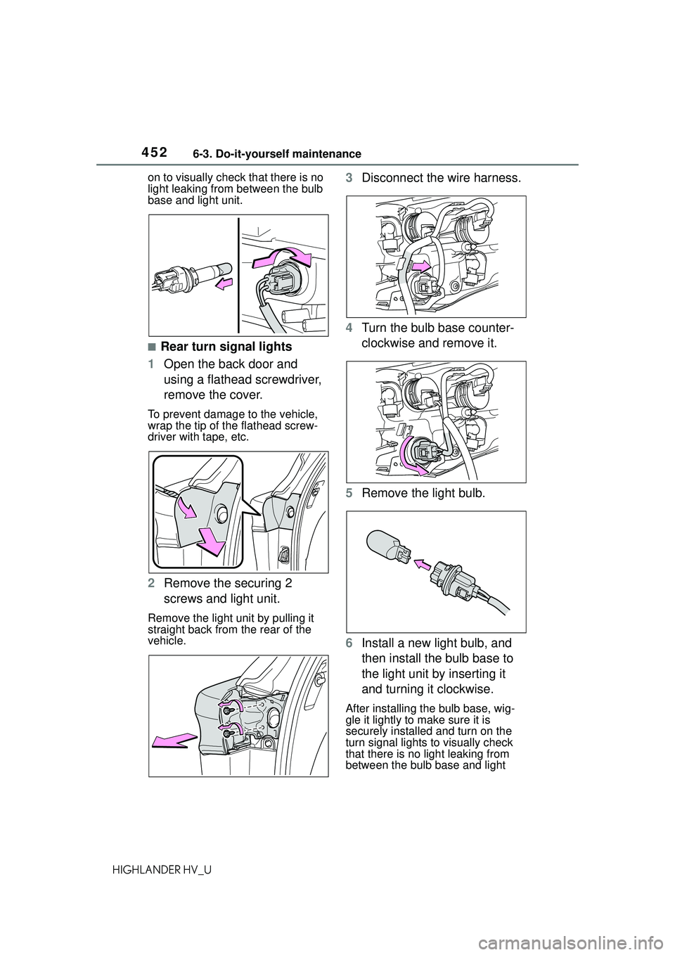
HIGHLANDER HV_Uon to visually check that there is no
light leaking from between the bulb
base and light unit.
■Rear turn signal lights
1 Open the back door and
using a flathead screwdriver,
remove the cover.
To prevent damage to the vehicle,
wrap the tip of the flathead screw-
driver with tape, etc.
2Remove the securing 2
screws and light unit.
Remove the light unit by pulling it
straight back from the rear of the
vehicle.
3Disconnect the wire harness.
4 Turn the bulb base counter-
clockwise and remove it.
5 Remove the light bulb.
6 Install a new light bulb, and
then install the bulb base to
the light unit by inserting it
and turning it clockwise.
After installing the bulb base, wig-
gle it lightly to make sure it is
securely installed and turn on the
turn signal lights to visually check
that there is no light leaking from
between the bulb base and light