fuse TOYOTA MIRAI 2022 Owners Manual
[x] Cancel search | Manufacturer: TOYOTA, Model Year: 2022, Model line: MIRAI, Model: TOYOTA MIRAI 2022Pages: 556, PDF Size: 17.34 MB
Page 4 of 556
4TABLE OF CONTENTS
Owners Manual_USA_M62084_en
6-1. Using the air conditioning
system and defogger
ALL AUTO control ......... 324
Automatic air conditioning system (vehicles with 8-inch
display) ........................ 325
Automatic air conditioning system (vehicles with 12.3-
inch display) ................ 332
Rear automatic air condition- ing system ................... 341
Heated steering wheel/seat heaters/seat ventilators 342
6-2. Using the interior lights Interior lights list ............ 346
6-3. Using the storage features List of storage features . 349
Trunk features ............... 352
6-4. Using the other interior fea- tures
Toyota multi-operation touch
(vehicle with the 12.3-inch
display) ........................ 353
Electronic sunshade...... 355
Other interior features ... 356
Garage door opener...... 371
7-1. Maintenance and care Cleaning and protecting the vehicle exterior ............ 380
Cleaning and protecting the vehicle interior ............. 3847-2. Maintenance
Maintenance requirements.................................... 387
General maintenance .... 388
7-3. Do-it-yourself maintenance Do-it-yourself service precau-tions ............................. 391
Hood .............................. 393
Positioning a floor jack .. 393
Fuel cell unit compartment .................................... 395
12-volt battery................ 400
Tires .............................. 403
Replacing the tire .......... 411
Tire inflation pressure .... 415
Wheels .......................... 417
Air conditioning filter ...... 419
Cleaning the traction battery air intake vents and filters
.................................... 420
Electronic key battery .... 423
Checking and replacing fuses .................................... 425
Headlight aim ................ 428
Light bulbs ..................... 429
8-1. Essential information Emergency flashers....... 432
If your vehicle has to be stopped in an emergency.................................... 432
If the vehicle is submerged or water on the road is rising.................................... 433
6Interior features
7Maintenance and care
8When trouble arises
Page 363 of 556
3636-4. Using the other interior features
Owners Manual_USA_M62084_en
6
Interior features
■The power outlet can be used
when
The power switch i s in ACC or ON.
■When stopping the fuel cell sys-
tem
Disconnect electrical devices with
charging functions, such as mobile
battery packs. If such devices are
left connected, the fuel cell system
may not stop normally.
Please use as a power supply
for electronic devices that use
less than 120 VAC (power con-
sumption of 1500 W).
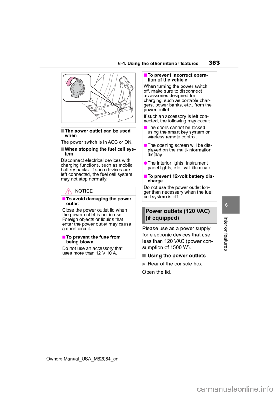
■Using the power outlets
Rear of the console box
Open the lid.
NOTICE
■To avoid damaging the power
outlet
Close the power outlet lid when
the power outlet is not in use.
Foreign objects or liquids that
enter the power outlet may cause
a short circuit.
■To prevent the fuse from
being blown
Do not use an accessory that
uses more than 12 V 10 A.
■To prevent inc orrect opera-
tion of the vehicle
When turning the power switch
off, make sure to disconnect
accessories designed for
charging, such as portable char-
gers, power banks, etc., from the
power outlet.
If such an accesso ry is left con-
nected, the following may occur:
●The doors cannot be locked
using the smart key system or
wireless remote control.
●The opening screen will be dis-
played on the multi-information
display.
●The interior lights, instrument
panel lights, etc., will illuminate.
■To prevent 12-volt battery dis-
charge
Do not use the p ower outlet lon-
ger than necessary when the fuel
cell system is off.
Power outlets (120 VAC)
(if equipped)
Page 379 of 556
379
Owners Manual_USA_M62084_en
7
7
Maintenance and care
Maintenance and care
7-1. Maintenance and careCleaning and protecting the vehicle exterior .......... 380
Cleaning and protecting the vehicle interior ........... 384
7-2. Maintenance Maintenance requirements.................................. 387
General maintenance.. 388
7-3. Do-it-yourself mainte- nance
Do-it-yourself service pre- cautions ..................... 391
Hood ........................... 393
Positioning a floor jack 393
Fuel cell unit compartment .................................. 395
12-volt battery ............. 400
Tires ............................ 403
Replacing the tire ........ 411
Tire inflation pressure.. 415
Wheels ......... ...............417
Air conditioning filter .... 419
Cleaning the traction battery air intake vents and filters.................................. 420
Electronic key battery.. 423
Checking and replacing fuses.......................... 425
Headlight aim .............. 428
Light bulbs................... 429
Page 391 of 556
3917-3. Do-it-yourself maintenance
Owners Manual_USA_M62084_en
7
Maintenance and care
7-3.Do-it-yourself maintenance
Do-it-yourself ser vice
precautions
If you perform maintenance
by yourself, be sure to fol-
low the correct procedure
as given in these sections.
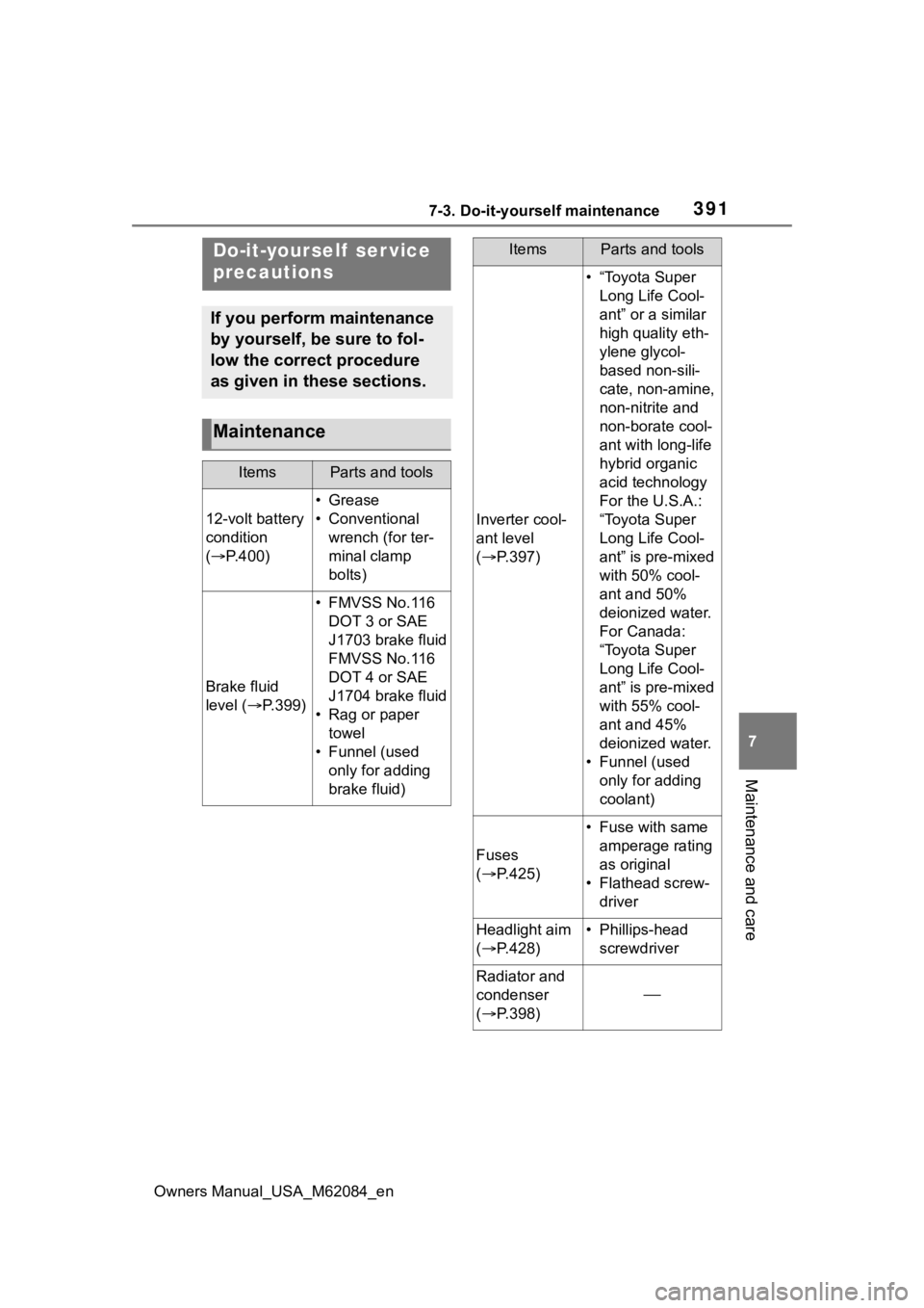
Maintenance
ItemsParts and tools
12-volt battery
condition
( P.400)
•Grease
• Conventional
wrench (for ter-
minal clamp
bolts)
Brake fluid
level ( P.399)
• FMVSS No.116
DOT 3 or SAE
J1703 brake fluid
FMVSS No.116
DOT 4 or SAE
J1704 brake fluid
• Rag or paper towel
• Funnel (used only for adding
brake fluid)
Inverter cool-
ant level
( P.397)
• “Toyota Super
Long Life Cool-
ant” or a similar
high quality eth-
ylene glycol-
based non-sili-
cate, non-amine,
non-nitrite and
non-borate cool-
ant with long-life
hybrid organic
acid technology
For the U.S.A.:
“Toyota Super
Long Life Cool-
ant” is pre-mixed
with 50% cool-
ant and 50%
deionized water.
For Canada:
“Toyota Super
Long Life Cool-
ant” is pre-mixed
with 55% cool-
ant and 45%
deionized water.
• Funnel (used only for adding
coolant)
Fuses
( P.425)
• Fuse with same
amperage rating
as original
• Flathead screw- driver
Headlight aim
( P.428)• Phillips-head
screwdriver
Radiator and
condenser
( P.398)
ItemsParts and tools
Page 395 of 556
3957-3. Do-it-yourself maintenance
Owners Manual_USA_M62084_en
7
Maintenance and care
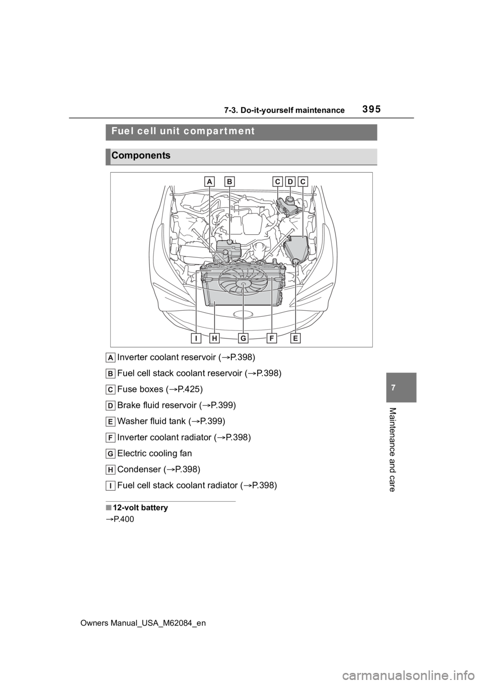
Inverter coolant reservoir ( P.398)
Fuel cell stack coolant reservoir ( P.398)
Fuse boxes ( P.425)
Brake fluid reservoir ( P.399)
Washer fluid tank ( P.399)
Inverter coolant radiator ( P.398)
Electric cooling fan
Condenser ( P.398)
Fuel cell stack coolant radiator ( P.398)
■12-volt battery
P. 4 0 0
Fuel cell unit compartment
Components
Page 425 of 556
4257-3. Do-it-yourself maintenance
Owners Manual_USA_M62084_en
7
Maintenance and care
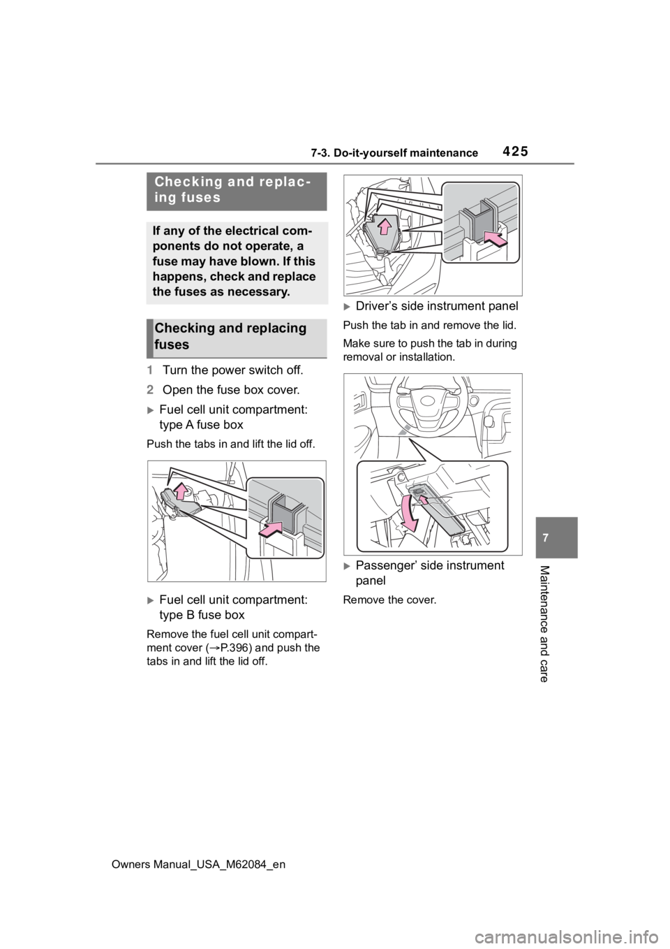
1 Turn the power switch off.
2 Open the fuse box cover.
Fuel cell unit compartment:
type A fuse box
Push the tabs in and lift the lid off.
Fuel cell unit compartment:
type B fuse box
Remove the fuel cell unit compart-
ment cover (P.396) and push the
tabs in and lift the lid off.
Driver’s side instrument panel
Push the tab in and remove the lid.
Make sure to push the tab in during
removal or installation.
Passenger’ side instrument
panel
Remove the cover.
Checking and replac-
ing fuses
If any of the electrical com-
ponents do not operate, a
fuse may have blown. If this
happens, check and replace
the fuses as necessary.
Checking and replacing
fuses
Page 427 of 556
4277-3. Do-it-yourself maintenance
Owners Manual_USA_M62084_en
7
Maintenance and care
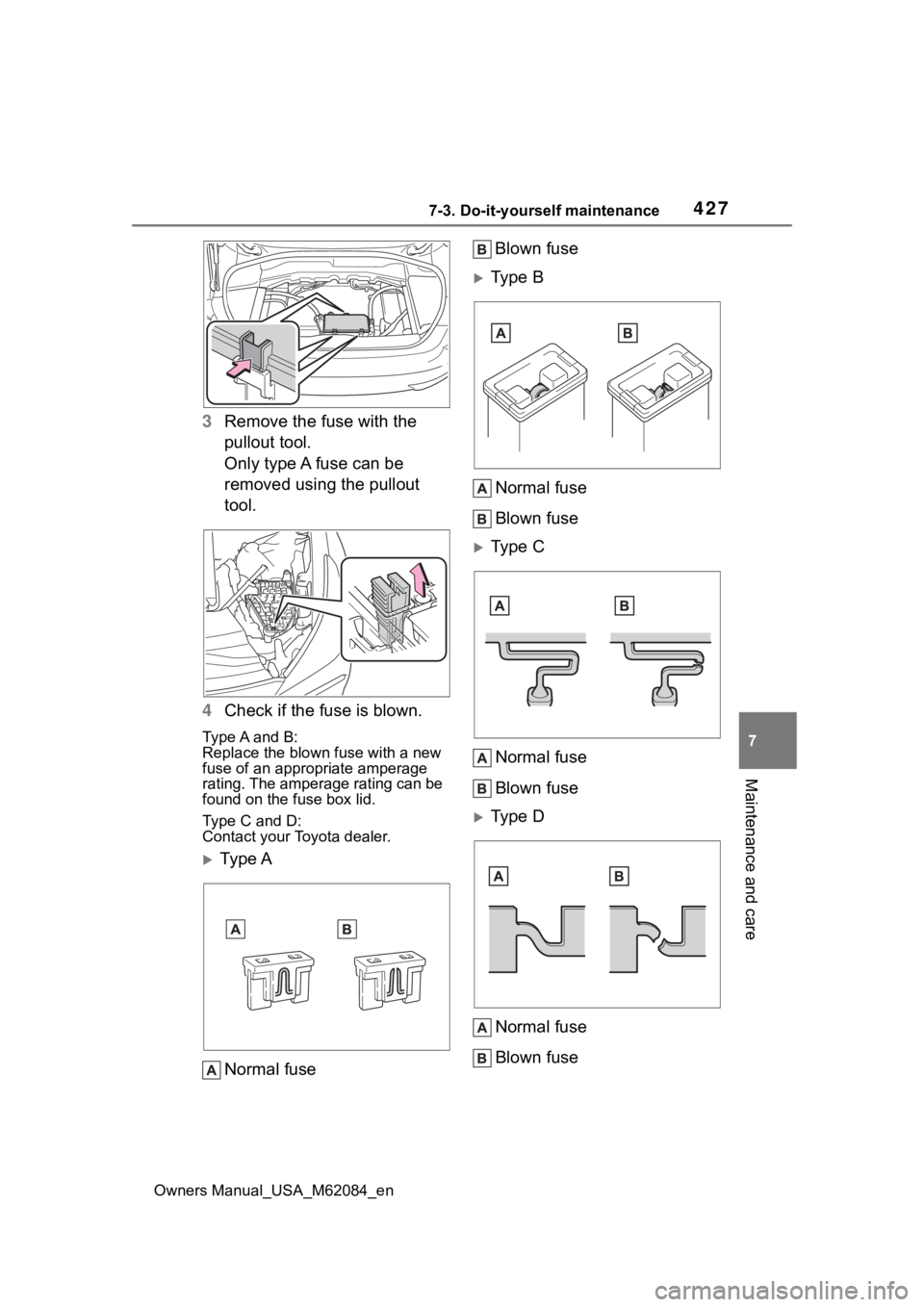
3 Remove the fuse with the
pullout tool.
Only type A fuse can be
removed using the pullout
tool.
4 Check if the fuse is blown.
Type A and B:
Replace the blown fuse with a new
fuse of an appropriate amperage
rating. The amperage rating can be
found on the fuse box lid.
Type C and D:
Contact your Toyota dealer.
Ty p e A
Normal fuse Blown fuse
Type B
Normal fuse
Blown fuse
Type CNormal fuse
Blown fuse
Type DNormal fuse
Blown fuse
Page 428 of 556
4287-3. Do-it-yourself maintenance
Owners Manual_USA_M62084_en
■After a fuse is replaced
●When installing the lid, make sure
that the tab is installed securely.
●If the lights do not turn on even
after the fuse has been replaced,
a bulb may need replacement.
●If the replaced fuse blows again,
have the vehicle inspected by
your Toyota dealer.
■If there is an overload in a cir-
cuit
The fuses are designed to blow, pro-
tecting the wiring harness from
damage.
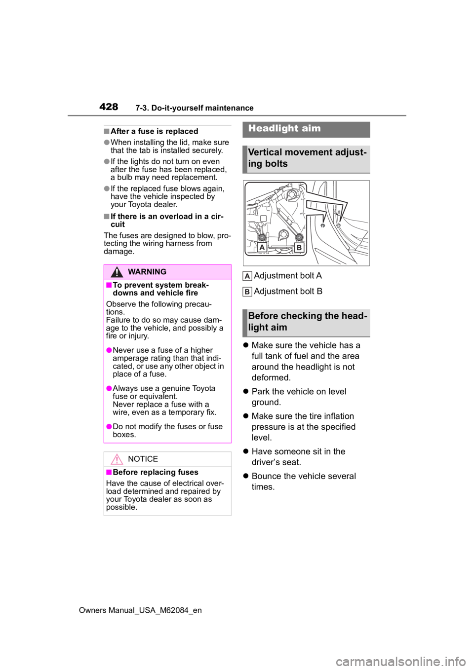
Adjustment bolt A
Adjustment bolt B
Make sure the vehicle has a
full tank of fuel and the area
around the headlight is not
deformed.
Park the vehicle on level
ground.
Make sure the tire inflation
pressure is at the specified
level.
Have someone sit in the
driver’s seat.
Bounce the vehicle several
times.WARNING
■To prevent system break-
downs and vehicle fire
Observe the following precau-
tions.
Failure to do so may cause dam-
age to the vehicle, and possibly a
fire or injury.
●Never use a fuse of a higher
amperage rating than that indi-
cated, or use any other object in
place of a fuse.
●Always use a genuine Toyota
fuse or equivalent.
Never replace a fuse with a
wire, even as a temporary fix.
●Do not modify the fuses or fuse
boxes.
NOTICE
■Before replacing fuses
Have the cause of electrical over-
load determined and repaired by
your Toyota dealer as soon as
possible.
Headlight aim
Vertical movement adjust-
ing bolts
Before checking the head-
light aim
Page 466 of 556
4668-2. Steps to take in an emergency
Owners Manual_USA_M62084_en
One of the following may be the
cause of the problem:
The electronic key may not be
functioning properly.
( P.468)
There may not be sufficient
fuel in the vehicle’s tank.
Refuel the vehicle.
The fuel door may be open.
( P.205)
There may be a malfunction
in the immobilizer system.
( P. 6 9 )
There may be a malfunction
in the shift control system.
*
( P.175, 453)
There may be a malfunction
in the steering lock system.
The fuel cell system may be
malfunctioning due to an elec-
trical problem such as elec- tronic key battery depletion or
a blown fuse. However,
depending on the type of mal-
function, an interim measure
is available to start the fuel
cell system. (
P.467)
There is a possibility that the
temperature of the traction
battery is extremely low
(approximately below -22˚F [-
30˚C]). ( P.83, 172)
It is possible the fuel cell sys-
tem is frozen. ( P.172)
*: It may not be possible to shift the
shift position from P.
One of the following may be the
cause of the problem:
The 12-volt battery may be
discharged. ( P.471)
The 12-volt battery terminal
connections may be loose or
corroded. ( P.400)
One of the following may be the
cause of the problem:
One or both of the 12-volt bat-
tery terminals may be discon-
If the fuel cell system
will not start
Reasons for the fuel cell
system not starting vary
depending on the situation.
Check the following and
perform the appropriate
procedure:
The fuel cell system will
not start even though the
correct starting procedure
is being followed.
( P.172)
The interior lights and
headlights are dim, or the
horn does not sound or
sounds at a low volume.
The interior lights and
headlights do not turn on,
or the horn does not
sound.
Page 471 of 556
4718-2. Steps to take in an emergency
Owners Manual_USA_M62084_en
8
When trouble arises
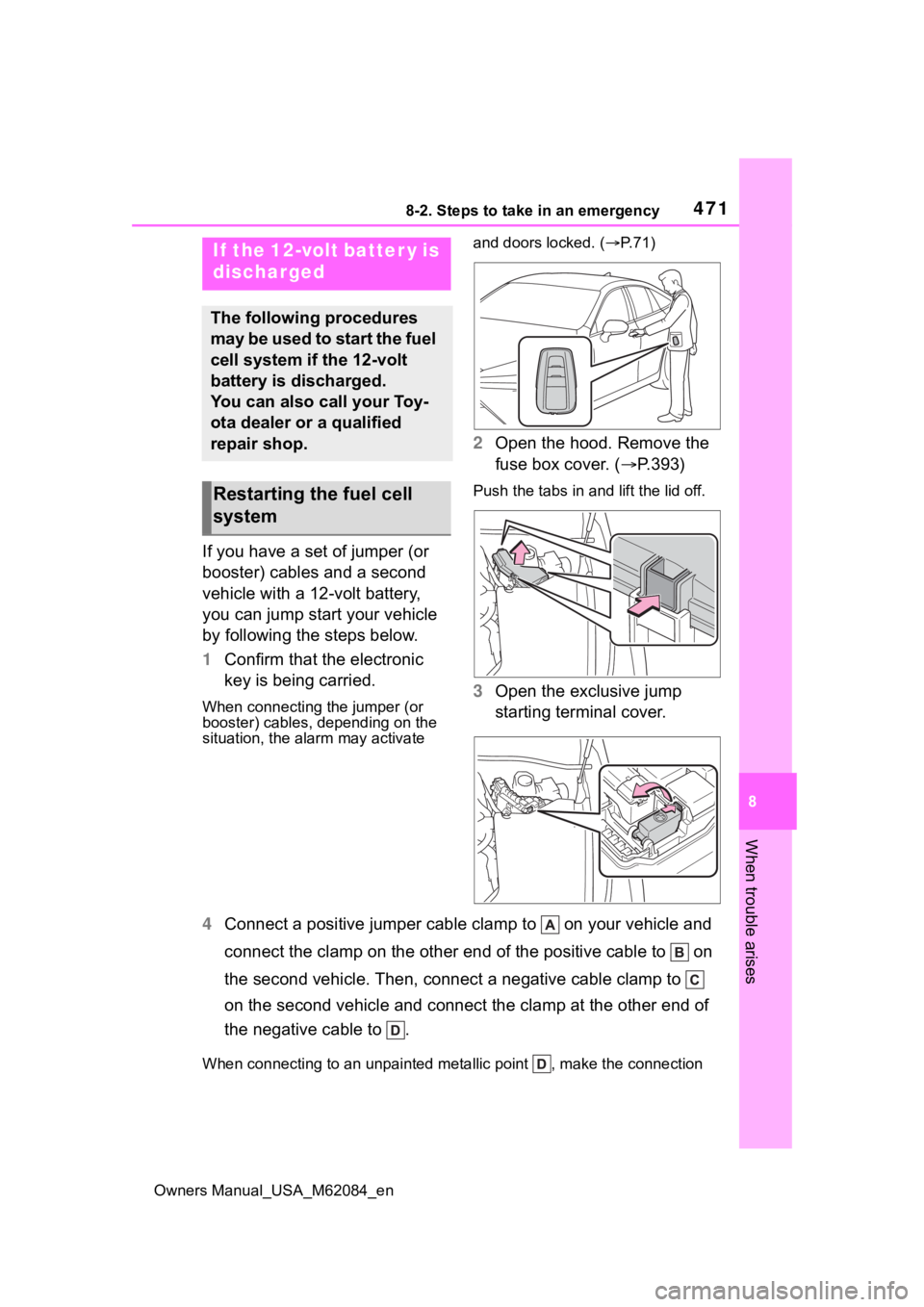
If you have a set of jumper (or
booster) cables and a second
vehicle with a 12-volt battery,
you can jump start your vehicle
by following the steps below.
1 Confirm that the electronic
key is being carried.
When connecting the jumper (or
booster) cables, depending on the
situation, the ala rm may activate and doors locked. (
P. 7 1 )
2 Open the hood. Remove the
fuse box cover. ( P.393)
Push the tabs in and lift the lid off.
3 Open the exclusive jump
starting terminal cover.
4 Connect a positive jumper cabl e clamp to on your vehicle and
connect the clamp on the other end of the positive cable to on
the second vehicle. Then, connect a negative cable clamp to
on the second vehicle and connect the clamp at the other end of
the negative cable to .
When connecting to an unpaint ed metallic point , make the connection
If the 12-volt batter y is
discharged
The following procedures
may be used to start the fuel
cell system if the 12-volt
battery is discharged.
You can also call your Toy-
ota dealer or a qualified
repair shop.
Restarting the fuel cell
system