battery TOYOTA PRIUS 2001 Service Repair Manual
[x] Cancel search | Manufacturer: TOYOTA, Model Year: 2001, Model line: PRIUS, Model: TOYOTA PRIUS 2001Pages: 1943, PDF Size: 18.26 MB
Page 3 of 1943

2001 PRIUS (EWD414U)
HOW TO USE THIS MANUAL B
This manual provides information on the electrical circuits installed on vehicles by
dividing them into a circuit for each system.
The actual wiring of each system circuit is shown from the point where the power
source is received from the battery as far as each ground point. (All circuit
diagrams are shown with the switches in the OFF position.)
When troubleshooting any problem, first understand the operation of the circuit
where the problem was detected (see System Circuit section), the power source
supplying power to that circuit (see Power Source section), and the ground points
(see Ground Point section). See the System Outline to understand the circuit
operation.
When the circuit operation is understood, begin troubleshooting of the problem
circuit to isolate the cause. Use Relay Location and Electrical Wiring Routing
sections to find each part, junction block and wiring harness connectors, wiring
harness and wiring harness connectors, splice points, and ground points of each
system circuit. Internal wiring for each junction block is also provided for better
understanding of connection within a junction block.
Wiring related to each system is indicated in each system circuit by arrows
(from__, to__). When overall connections are required, see the Overall Electrical
Wiring Diagram at the end of this manual.
Page 9 of 1943
2001 PRIUS (EWD414U)
B
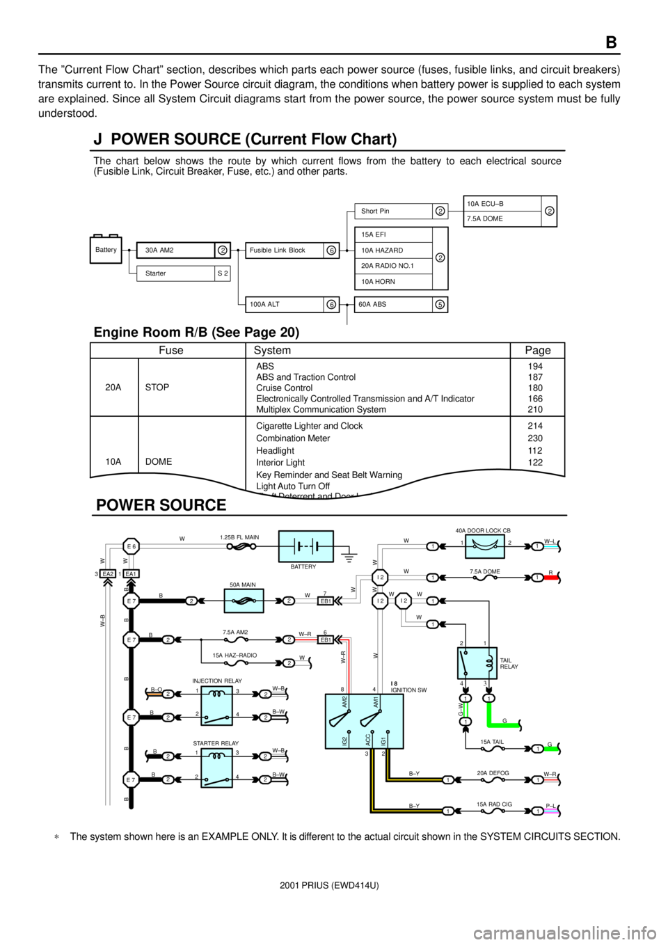
The ºCurrent Flow Chartº section, describes which parts each power source (fuses, fusible links, and circuit breakers)
transmits current to. In the Power Source circuit diagram, the conditions when battery power is supplied to each system
are explained. Since all System Circuit diagrams start from the power source, the power source system must be fully
understood.
Theft Deterrent and Door Lock Control
J POWER SOURCE (Current Flow Chart)
11
1
EA1 1EA2 3
7
EB16
E 6
E 7I 2I 2
I 2
E 7
E 7
E 7
2
1
1
2
2
2
2
2
B
B
W W
B B B B BW±B
B
B
B B±O
B±W
W±B
B±W STARTER RELAY INJECTION RELAY15A HAZ±RADIO7.5A AM250A MAIN 1.25B FL MAIN
BATTERY
WWW
W W W
R W±L
W
W
G±W
G
15A TAIL
20A DEFOG
15A RAD CIGTA I L
RELAY 7.5A DOME 40A DOOR LOCK CB
2 1
1 2
4 8
2 3
3 4
G
W±R
P±L B±Y
B±Y
W±R
AM2 IG2
ACC
IG1AM1W W
W±R
W W
W±B
21
1
1
1
1
2
2
2
2
3
4
3
4 1
2
1
22
1
11
1
IGNITION SW I 8
Battery
30A AM2
2
Starter S 220A RADIO NO.1
10A HORN
15A EFI
7.5A DOMEShort Pin
10A HAZARD
The chart below shows the route by which current flows from the battery to each electrical source
(Fusible Link, Circuit Breaker, Fuse, etc.) and other parts.
Engine Room R/B (See Page 20)
ABS
ABS and Traction Control
Cruise Control
Electronically Controlled Transmission and A/T Indicator
Multiplex Communication System
Cigarette Lighter and Clock
Key Reminder and Seat Belt Warning STOP
Fuse Page
194
214
11 2
System
DOME 20A
10ACombination Meter
Headlight
Interior Light
2
2
6 100A ALT
EB1
POWER SOURCE
Light Auto Turn Off187
180
166
210
230
122
10A ECU±B
5 60A ABS
2
6 Fusible Link Block2
*The system shown here is an EXAMPLE ONLY. It is different to the actual circuit shown in the SYSTEM CIRCUITS SECTION.
Page 12 of 1943
![TOYOTA PRIUS 2001 Service Repair Manual To Ignition SW
IG Terminal
Fuse
Voltmeter SW 1
Relay
SW 2Solenoid[A]
[B]
[C]
Ohmmeter
SW
Ohmmeter
Diode
Digital Type Analog Type
2001 PRIUS (EWD414U)
C TROUBLESHOOTING
VOLTAGE CHECK
(a)Establish cond TOYOTA PRIUS 2001 Service Repair Manual To Ignition SW
IG Terminal
Fuse
Voltmeter SW 1
Relay
SW 2Solenoid[A]
[B]
[C]
Ohmmeter
SW
Ohmmeter
Diode
Digital Type Analog Type
2001 PRIUS (EWD414U)
C TROUBLESHOOTING
VOLTAGE CHECK
(a)Establish cond](/img/14/57461/w960_57461-11.png)
To Ignition SW
IG Terminal
Fuse
Voltmeter SW 1
Relay
SW 2Solenoid[A]
[B]
[C]
Ohmmeter
SW
Ohmmeter
Diode
Digital Type Analog Type
2001 PRIUS (EWD414U)
C TROUBLESHOOTING
VOLTAGE CHECK
(a)Establish conditions in which voltage is present at the check
point.
Example:
[A] ± Ignition SW on
[B] ± Ignition SW and SW 1 on
[C] ± Ignition SW, SW 1 and Relay on (SW 2 off)
(b)Using a voltmeter, connect the negative lead to a good ground
point or negative battery terminal, and the positive lead to the
connector or component terminal.
This check can be done with a test light instead of a voltmeter.
CONTINUITY AND RESISTANCE CHECK
(a)Disconnect the battery terminal or wire so there is no voltage
between the check points.
(b)Contact the two leads of an ohmmeter to each of the check
points.
If the circuit has diodes, reverse the two leads and check
again.
When contacting the negative lead to the diode positive side
and the positive lead to the negative side, there should be
continuity.
When contacting the two leads in reverse, there should be no
continuity.
(c)Use a volt/ohmmeter with high impedance (10 kW/V
minimum) for troubleshooting of the electrical circuit.
Page 18 of 1943
2001 PRIUS (EWD414U)
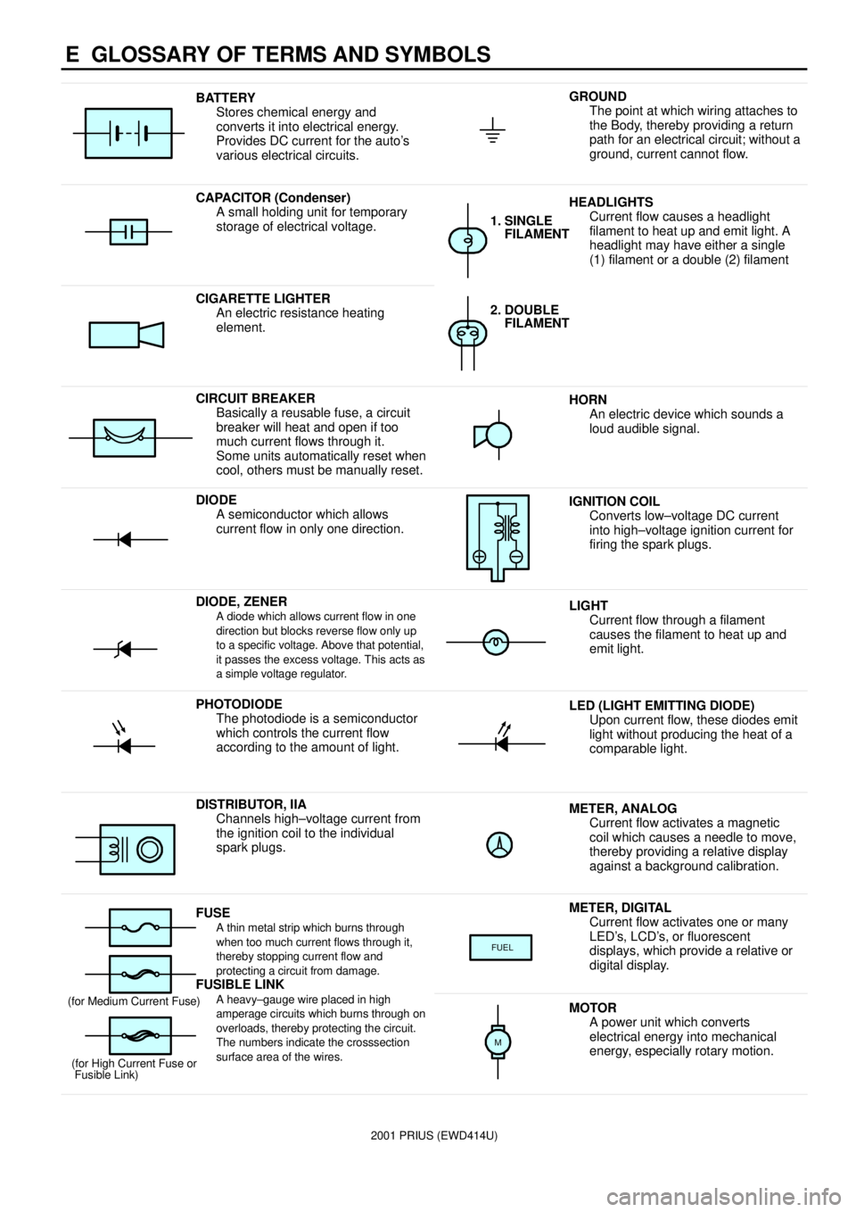
E GLOSSARY OF TERMS AND SYMBOLS
BATTERY
Stores chemical energy and
converts it into electrical energy.
Provides DC current for the auto's
various electrical circuits.GROUND
The point at which wiring attaches to
the Body, thereby providing a return
path for an electrical circuit; without a
ground, current cannot flow.
CAPACITOR (Condenser)
A small holding unit for temporary
storage of electrical voltage.HEADLIGHTS
Current flow causes a headlight
filament to heat up and emit light. A
headlight may have either a single
(1) filament or a double (2) filament
1. SINGLE
FILAMENT
CIGARETTE LIGHTER
An electric resistance heating
element.2. DOUBLE
FILAMENT
CIRCUIT BREAKER
Basically a reusable fuse, a circuit
breaker will heat and open if too
much current flows through it.
Some units automatically reset when
cool, others must be manually reset.HORN
An electric device which sounds a
loud audible signal.
DIODE
A semiconductor which allows
current flow in only one direction.IGNITION COIL
Converts low±voltage DC current
into high±voltage ignition current for
firing the spark plugs.
DIODE, ZENERA diode which allows current flow in one
direction but blocks reverse flow only up
to a specific voltage. Above that potential,
it passes the excess voltage. This acts as
a simple voltage regulator.LIGHT
Current flow through a filament
causes the filament to heat up and
emit light.
PHOTODIODE
The photodiode is a semiconductor
which controls the current flow
according to the amount of light.LED (LIGHT EMITTING DIODE)
Upon current flow, these diodes emit
light without producing the heat of a
comparable light.
DISTRIBUTOR, IIA
Channels high±voltage current from
the ignition coil to the individual
spark plugs.METER, ANALOG
Current flow activates a magnetic
coil which causes a needle to move,
thereby providing a relative display
against a background calibration.
FUSEA thin metal strip which burns through
when too much current flows through it,
thereby stopping current flow and
protecting a circuit from damage.
FUSIBLE LINK
METER, DIGITAL
Current flow activates one or many
LED's, LCD's, or fluorescent
displays, which provide a relative or
digital display.
FUEL
FUSIBLE LINK
A heavy±gauge wire placed in high
amperage circuits which burns through on
overloads, thereby protecting the circuit.
The numbers indicate the crosssection
surface area of the wires.(for Medium Current Fuse)
(for High Current Fuse or
Fusible Link)MOTOR
A power unit which converts
electrical energy into mechanical
energy, especially rotary motion.
M
Page 38 of 1943

2001 PRIUS (EWD414U)
G ELECTRICAL WIRING ROUTING
Position of Parts in Body
A 23 ABS Speed Sensor Rear LH
A 24 ABS Speed Sensor Rear RH
B 15 Battery Blower Motor
B 16 Battery Blower Motor Controller
B 17 Battery ECU
B 18 Battery ECU
B 19 Battery Fan Relay
B 20 Buckle SW and Tension Reducer LH
B 21 Buckle SW RH and
Seat Belt Warning Occupant Detection Sensor
D 6 Door Courtesy SW Front LH
D 7 Door Courtesy SW Front RH
D 8 Door Courtesy SW Rear LH
D 9 Door Courtesy SW Rear RH
D 10 Door Lock Control SW Front RH
D 11 Door Lock Motor and Door Unlock Detection SW
Rear LH
D 12 Door Lock Motor and Door Unlock Detection SW
Rear RH
D 13 Door Lock Motor, Door Key Lock and Unlock SW and
Door Unlock Detection SW Front LH
D 14 Door Lock Motor, Door Key Lock and Unlock SW and
Door Unlock Detection SW Front RHF 14 Front Door Speaker LH
F 15 Front Door Speaker RH
F 16 Fuel Pump and Fuel Sender
F 17 Fusible Link Block No.2
F 18 Fusible Link Block No.2
H 15 High Mounted Stop Light
H 16 Hybrid Vehicle Battery
H 17 Hybrid Vehicle Battery
I 16 Interior Light
I 17 Interlock SW
J 30 Junction Connector
J 31 Junction Connector
J 32 Junction Connector
J 33 Junction Connector
L 2 License Plate Light LH
L 3 License Plate Light RH
L 4 Luggage Compartment Door Unlock SW
L 5 Luggage Compartment Light
L 6 Luggage Compartment Light SW
Page 48 of 1943
2001 PRIUS (EWD414U)
POWER SOURCE
B 1B 1A1
D 1C131240A ABS NO. 1
1250A EMPS
1250A HTR3
12
123
3
3
3
3
1
3 1B3
1B1
21
1
42
341
42
3 1 1B2
1J9 W
W
W
W
W
FUSIBLE
LINK BLOCK NO. 1D F12 C , F1 3B F10 A , F1 1
30A CDS FAN
15A THRO15A EFI
10A HORN
10A TURN±HAZ
15A DOME
10A BATT FAN15A AM2
20A ABS NO. 3 20A HV
10A HEAD LO (
RH)
10A HEAD LO (
LH)
10A HEAD HI (
LH)
10A HEAD HI (
RH) SHORT PIN SHORT PIN
HEAD RELAY
BATTERY5A DC/DC±S
B±G
B
B
B
W± RW
30A HTR2
30A HTR1
10A ABS NO. 4 100A
DC/DC
120A
MAIN30A HEAD (
*1)
(
*2)
DIM RELAYW±R 12 12
30A RDI 50A HTR
2W±R
B±R
G
G±W
B±R
L2C2
2G1
1230A ABS NO. 2
3127. 5A DRL
3R±L 12(
*1)
(
*2)
1J 11
R
TO CONVERTER
A2
B±R
TO CONVERTER
FUSIBLE LINK
BLOCK NO. 2B F17 , F18A
1 5SHORT PIN
(
*2)
Page 52 of 1943
2001 PRIUS (EWD414U)
TOYOTA HYBRID SYSTEM
C 1
1D1B 215A
AM2 1J 9ST2IG2 AM2 6
BATTERY7
IGNITION SW I15
FUSIBLE
LINK
BLOCK
NO. 1D F1 2 , F13C
B±G B W±R W±R
2C 2
2G 1
120A MAIN
1
FUSIBLE
LINK BLOCK
NO. 2 F18A CACE 7
B B
ID1 63 4D 2D16 ST1± IGSW CCS
B±W
B±Y
L LB±W
B±W
E 6ST2
R±W
STOP LIGHT SW S 3
B±W 8
IGA AAAB A B A B AD 31 D24
5
A 4
CRUISE CONTROL SW
[COMB. SW] C14
W±B W±B
W±B
W±BW±B
W±B
D 1STP GND1 GND2
G±W
JUNCTION
CONNECTOR J17
FROM STOP LIGHT
SW
W±B JUNCTION
CONNECTORB J18 , J19A
JUNCTION
CONNECTORB J24 A , J25
H14 , D H13 , E H12 , B CH11, H10 A
HYBRID VEHICLE CONTROL ECU
B±W
CCS
CRUISE
RES/ACC
SET/COAST
CANCEL 11 2G52B
1J 3
32 51
1A 21K3
IK1 14
M
1 2
E 5
B±W B±W B±W
W±B W±B W±B
W± B
WATER PUMP MOTOR
(
INVERTER) W 3
IG2
RELAYB±W
B±W
R±W
W±B ECC
Page 58 of 1943
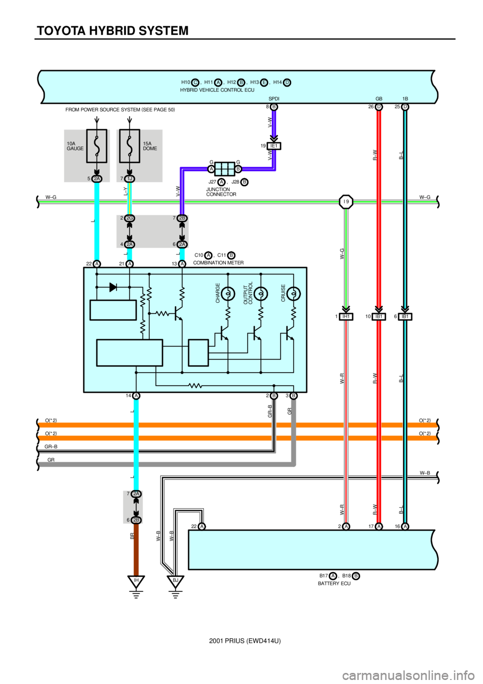
2001 PRIUS (EWD414U)
TOYOTA HYBRID SYSTEM
BJA 22A 17 A16 IB1 10 IB16 D 26 D25
R±W
B±L W± B W± B
R±W
B±LR±W
B± L
BATTERY ECUB B1 7 , B1 8A HYBRID VEHICLE CONTROL ECUA H10 , H11
CB, H12
E , H13
D , H14
GB 1B
O(
*2)
O(
*2)
IHO(
*2)
GR±B
GR
BR
10A
GAUGE FROM POWER SOURCE SYSTEM (
SEE PAGE 50)
2A 515A
DOME
1J 7
L±Y
2G 2
2A 4L
L
A 21 A 22
CHARGE
OU TPUT
CONTROL
CRUISE
A 14 B2
L
COMBINATION METERB C10 , C11A
LV±W
2B 7
2A 6
A 13A G
B GIE1 19B 8SPDI
JUNCTION
CONNECTORB J27 , J28A
V±W V±W
W±R
2A 1IH1I 9 W±GW±G
B 3
62B 72AO(
*2)
W±R GR GR±B L
W± B
W±G
Page 59 of 1943
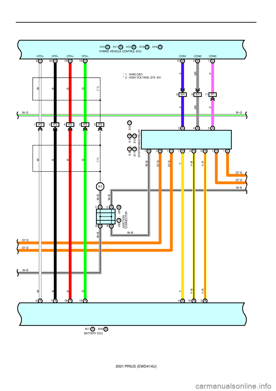
2001 PRIUS (EWD414U)
IH1 8IH19 B 13 B2
IF1 11E 1
B 4B10 B3 A 6A7A18 A19E 18 E 19 E 20 E 2
B 2
B B B BA CAC
W
B
R
GW
B
R
G
W± B
W± B
Y
Y±B
Y±RW
B
R
G
V
GR
P V
GR
P Y±RY±BY
W±B
BATTERY ECUB B17 , B18A
JUNCTION
CONNECTORB J32 A , J33
HYBRID VEHICLE CONTROL ECUA H10 , H11CB, H12 E, H13 D, H14
CON1 CON2 CON3 HTD+ HTD± DTH+ DTH±
* 1 : SHIELDED
B 1 A 1
W± B
O(
*2)IF2 5 IF2 1IF22IF24IF23* 2 : HIGH VOLTAGE (
273. 6V)
W±GW±G
1C 7A 2A 6A5A 4A 3A
1D 1E
O(
*2) O(
*2)
W± B
O(
*2)
O(
*2)(
*1) (
*1)
O(
*2)
W± B
W± B
SYSTEM MAIN RELAYE S11
D, S12C , S10 S 9 , A S 8 B
Page 60 of 1943
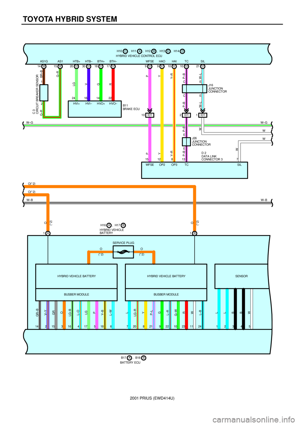
2001 PRIUS (EWD414U)
TOYOTA HYBRID SYSTEM
HYBRID VEHICLE CONTROL ECUA H10 , H11
CB, H12
E , H13
D , H14
W± BW± B HTB± BTH+
18 D
G
14
HVO+ HVO±22
R
D 17BTH±
30 D
V
16
HVI± HTB+
20 D
LG
24
HVI+ B 14 B15
1
2
G±R
G±R BR±B CIRCUIT BREAKER SENSOR C 3
AS1G AS1
BRAKE ECU B1 1
GR± B
V± Y
GR
O
LG±B
L±O
LG
P
Y± B
L±W
L
LG±R
Y
P±L
G
L±R
G± W
R
W
L±B
14 2 15 3 16 4 17 5 18 6 7 20 8 21 9 22 10 23 11 24HYBRID VEHICLE BATTERY
BUSBER MODULED 10TC
D 21SIL
D 9WF SE
ID1 2ID11 ID1 10CE
E
13 15C
E
P
P±B P±BY Y
P±B P
P±B
W± L W±L
EJUNCTION
CONNECTOR J1 6
TC WF SEE 10HAI
Y±R
E 9HAO
Y±R12
OP28
OP3JUNCTION
CONNECTOR J26 W±GW±G
W
1234
L
L
B
B
W
W
5
W
7
SIL
O(
*2) O(
*2)
A 1B 1
SERVICE PLUG
O
(
*2)O
(
*2)
HYBRID VEHICLE BATTERY
BUSBER MODULESENSOR
O O
(
*2)
(
*2)
HYBRID VEHICLE
BATTERYB H16 , H17A
BATTERY ECUB B17 , B18A
W
DATA LINK
CONNECTOR 3 D 2