AUX TOYOTA PRIUS V 2017 ZVW40 / 1.G User Guide
[x] Cancel search | Manufacturer: TOYOTA, Model Year: 2017, Model line: PRIUS V, Model: TOYOTA PRIUS V 2017 ZVW40 / 1.GPages: 624, PDF Size: 13.82 MB
Page 384 of 624
384
PRIUS v_OM_OM47B23U_(U)
6-3. Using the storage features
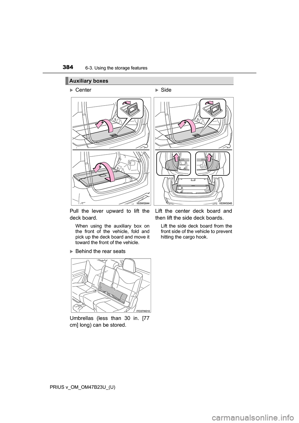
Auxiliary boxes
Center Side
Pull the lever upward to lift the
deck board.
When using the auxiliary box on
the front of the vehicle, fold and
pick up the deck board and move it
toward the front of the vehicle.
Lift the center deck board and
then lift the side deck boards.
Lift the side deck board from the
front side of the vehicle to prevent
hitting the cargo hook.
Behind the rear seats
Umbrellas (less than 30 in. [77
cm] long) can be stored.
Page 386 of 624
386
PRIUS v_OM_OM47B23U_(U)
6-3. Using the storage features
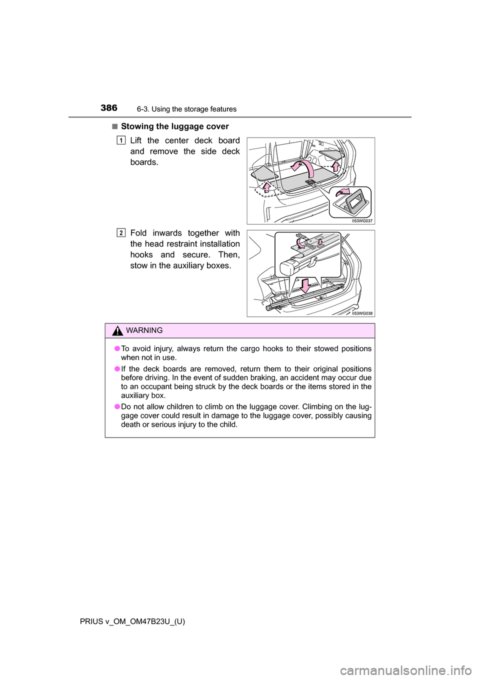
■Stowing the luggage cover
Lift the center deck board
and remove the side deck
boards.
Fold inwards together with
the head restraint installation
hooks and secure. Then,
stow in the auxiliary boxes.
1
2
WARNING
●To avoid injury, always return the cargo hooks to their stowed positions
when not in use.
● If the deck boards are removed, return them to their original positions
before driving. In the event of sudden braking, an accident may occur due
to an occupant being struck by the deck boards or the items stored in the
auxiliary box.
● Do not allow children to climb on the luggage cover. Climbing on the lug-
gage cover could result in damage to the luggage cover, possibly causing
death or serious injury to the child.
Page 424 of 624
424
PRIUS v_OM_OM47B23U_(U)
7-3. Do-it-yourself maintenance
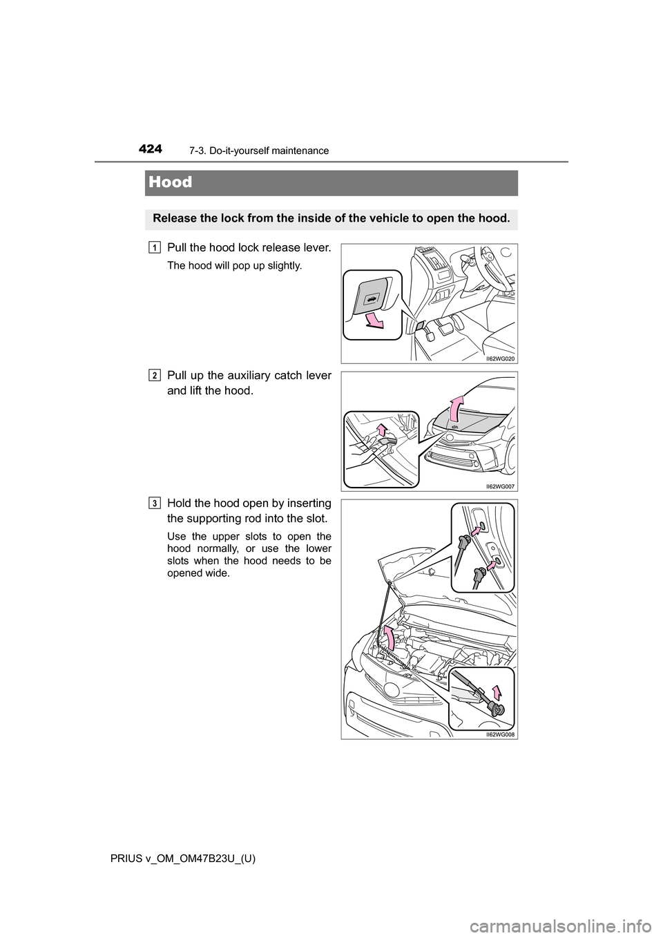
Hood
Pull the hood lock release lever.
The hood will pop up slightly.
Pull up the auxiliary catch lever
and lift the hood.
Hold the hood open by inserting
the supporting rod into the slot.
Use the upper slots to open the
hood normally, or use the lower
slots when the hood needs to be
opened wide.
Release the lock from the inside of the vehicle to open the hood.
1
2
3
Page 442 of 624
442
PRIUS v_OM_OM47B23U_(U)
7-3. Do-it-yourself maintenance
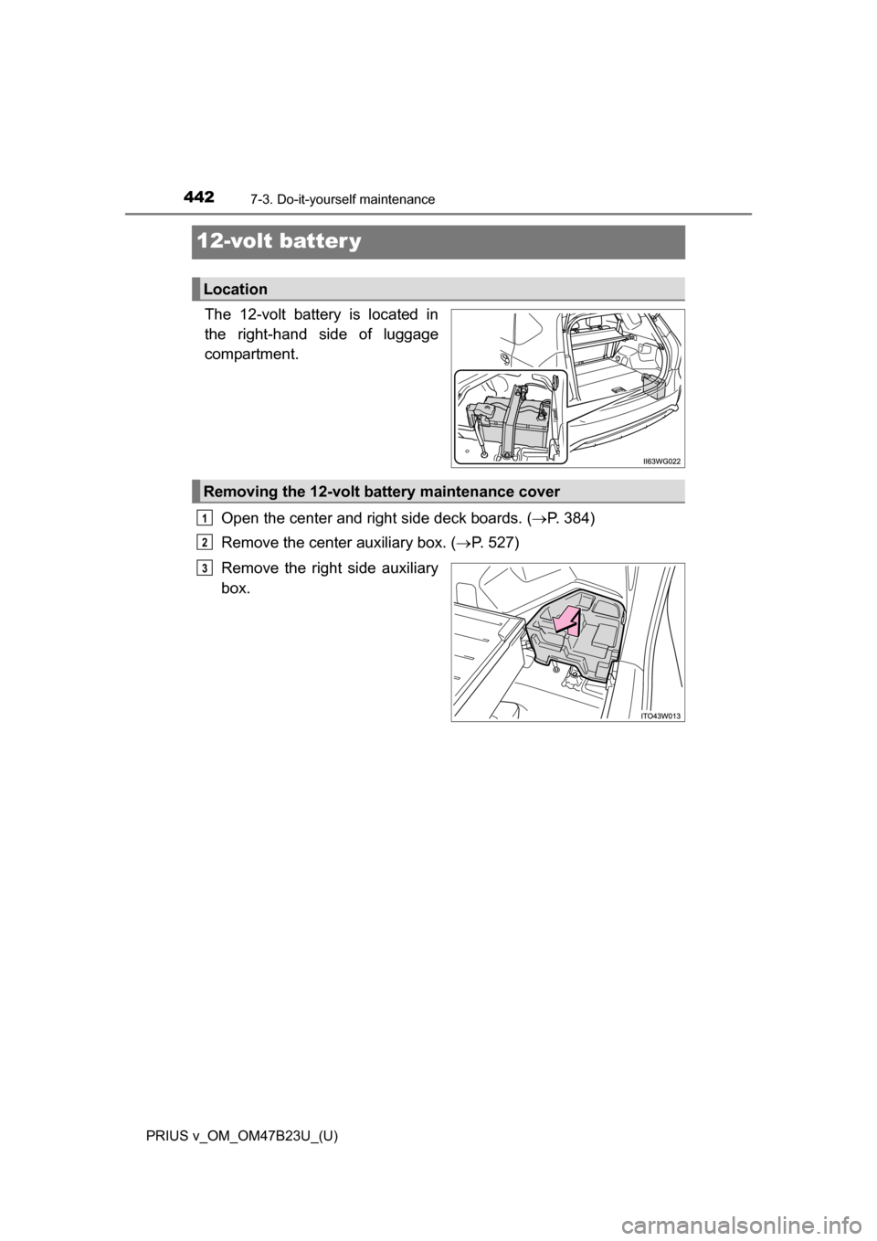
12-volt batter y
The 12-volt battery is located in
the right-hand side of luggage
compartment.Open the center and right side deck boards. ( P. 384)
Remove the center auxiliary box. (P. 527)
Remove the right side auxiliary
box.
Location
Removing the 12-volt battery maintenance cover
1
2
3
Page 451 of 624
PRIUS v_OM_OM47B23U_(U)
4517-3. Do-it-yourself maintenance
7
Maintenance and care
■Situations in which the tire pressu re warning system may not operate
properly
● In the following cases, the tire pressure warning system may not operate
properly.
• If non-genuine Toyota wheels are used.
• When a replacement tire is used, the system may not operate correctly
due to the structure of the replacement tire.
• A tire has been replaced with a tire that is not of the specified size.
• Tire chains etc. are equipped.
• An auxiliary-supported run-flat tire is equipped.
• If a window tint that affects the radio wave signals is installed.
• If there is a lot of snow or ice on the vehicle, particularly around the
wheels or wheel housings.
• If the tire inflation pressure is extremely higher than the specified level.
• If wheel without the tire pressure warning valve and transmitter is used.
• If the ID code on the tire pressure warning valves and transmitters is not registered in the tire pressure warning computer.
● Performance may be affected in the following situations.
• Near a TV tower, electric power plant, gas station, radio station, large dis-
play, airport or other facility that generates strong radio waves or electri-
cal noise
• When carrying a portable radio, cellular phone, cordless phone or other
wireless communication device
● When the vehicle is parked, the time taken for the warning to start or go off
could be extended.
● When tire inflation pressure declines rapidly for example when a tire has
burst, the warning may not function.
Page 527 of 624
5278-2. Steps to take in an emergency
PRIUS v_OM_OM47B23U_(U)
8
When trouble arises
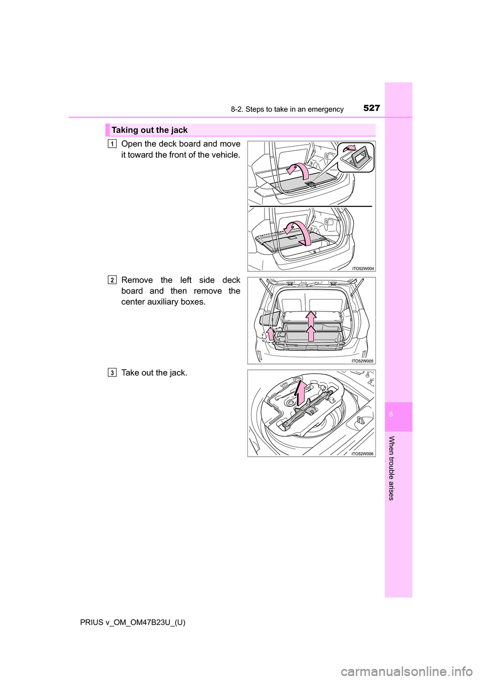
Open the deck board and move
it toward the front of the vehicle.
Remove the left side deck
board and then remove the
center auxiliary boxes.
Take out the jack.
Taking out the jack
1
2
3
Page 528 of 624
5288-2. Steps to take in an emergency
PRIUS v_OM_OM47B23U_(U)
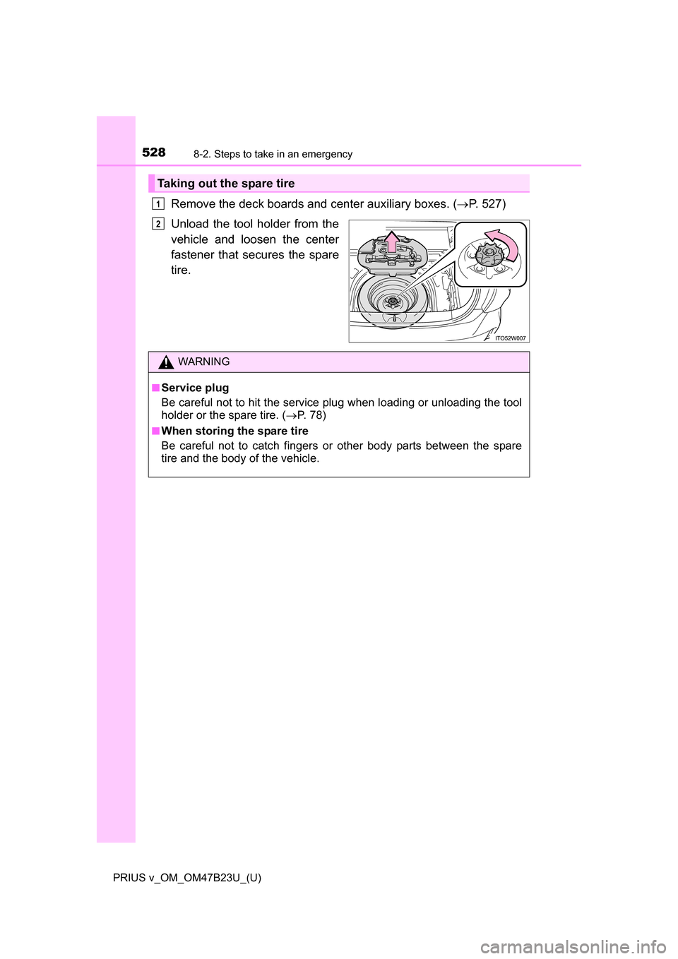
Remove the deck boards and center auxiliary boxes. (P. 527)
Unload the tool holder from the
vehicle and loosen the center
fastener that secures the spare
tire.
Taking out the spare tire
1
2
WARNING
■Service plug
Be careful not to hit the service plug when loading or unloading the tool
holder or the spare tire. ( P. 7 8 )
■When storing the spare tire
Be careful not to catch fingers or other body parts between the spare
tire and the body of the vehicle.
Page 592 of 624
592
PRIUS v_OM_OM47B23U_(U)
◆Coussins gonflables SRS latéraux et en rideauCoussins gonflables SRS latéraux
Peuvent aider à protéger le torse des occupants des sièges
avant
Coussins gonflabl es SRS en rideau
Peuvent aider à protéger principalement la tête des occupants
des sièges latéraux
3
4
Page 593 of 624
PRIUS v_OM_OM47B23U_(U)
593
10
For owners
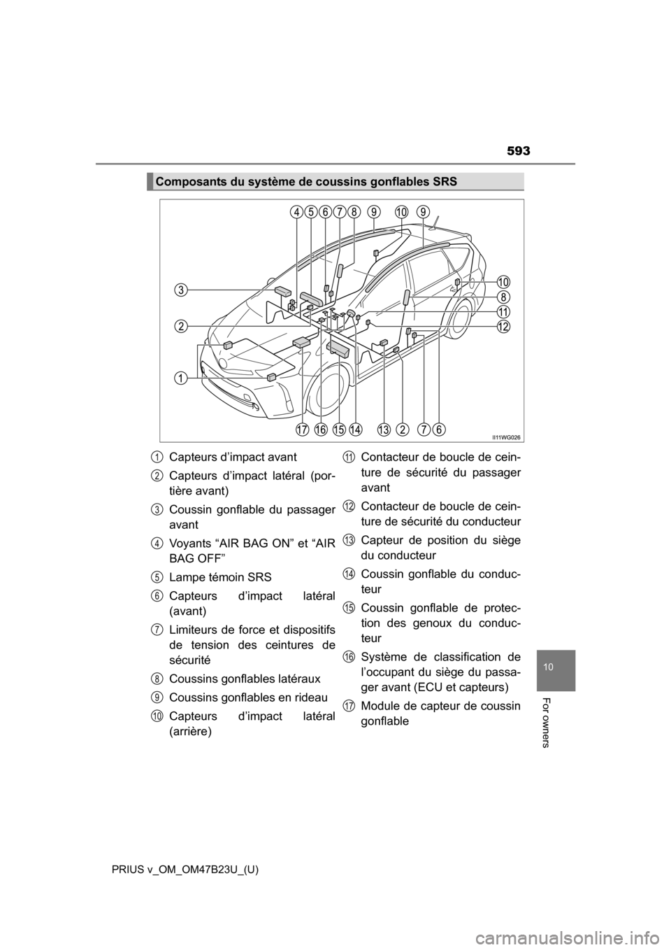
Composants du système de coussins gonflables SRS
Capteurs d’impact avant
Capteurs d’impact latéral (por-
tière avant)
Coussin gonflable du passager
avant
Voyants “AIR BAG ON” et “AIR
BAG OFF”
Lampe témoin SRS
Capteurs d’impact latéral
(avant)
Limiteurs de force et dispositifs
de tension des ceintures de
sécurité
Coussins gonflables latéraux
Coussins gonflables en rideau
Capteurs d’impact latéral
(arrière) Contacteur de boucle de cein-
ture de sécurité du passager
avant
Contacteur de boucle de cein-
ture de sécurité du conducteur
Capteur de position du siège
du conducteur
Coussin gonflable du conduc-
teur
Coussin gonflable de protec-
tion des genoux du conduc-
teur
Système de classification de
l’occupant du siège du passa-
ger avant (ECU et capteurs)
Module de capteur de coussin
gonflable1
2
3
4
5
6
7
8
9
10
11
12
13
14
15
16
17
Page 594 of 624
594
PRIUS v_OM_OM47B23U_(U)
Votre véhicule est doté de COUSSINS GONFLABLES ÉVOLUÉS
dont la conception s’appuie sur les normes de sécurité des véhicules
à moteur américains (FMVSS208). Le module de capteur de coussin
gonflable (ECU) contrôle le dépl oiement des coussins gonflables en
fonction des informations obtenues des capteurs et d’autres éléments
affichés dans le diagramme des composants du système ci-dessus.
Ces informations comprennent des données relatives à la gravité de
l’accident et aux occupants. Au moment du déploiement des coussins
gonflables, une réaction chimique se produit dans les gonfleurs de
coussin gonflable et les coussins gonflables se remplissent rapide-
ment d’un gaz non toxique pour aider à limiter le mouvement des
occupants.