cam belt TOYOTA RAV4 1996 Service Repair Manual
[x] Cancel search | Manufacturer: TOYOTA, Model Year: 1996, Model line: RAV4, Model: TOYOTA RAV4 1996Pages: 1632, PDF Size: 41.64 MB
Page 403 of 1632
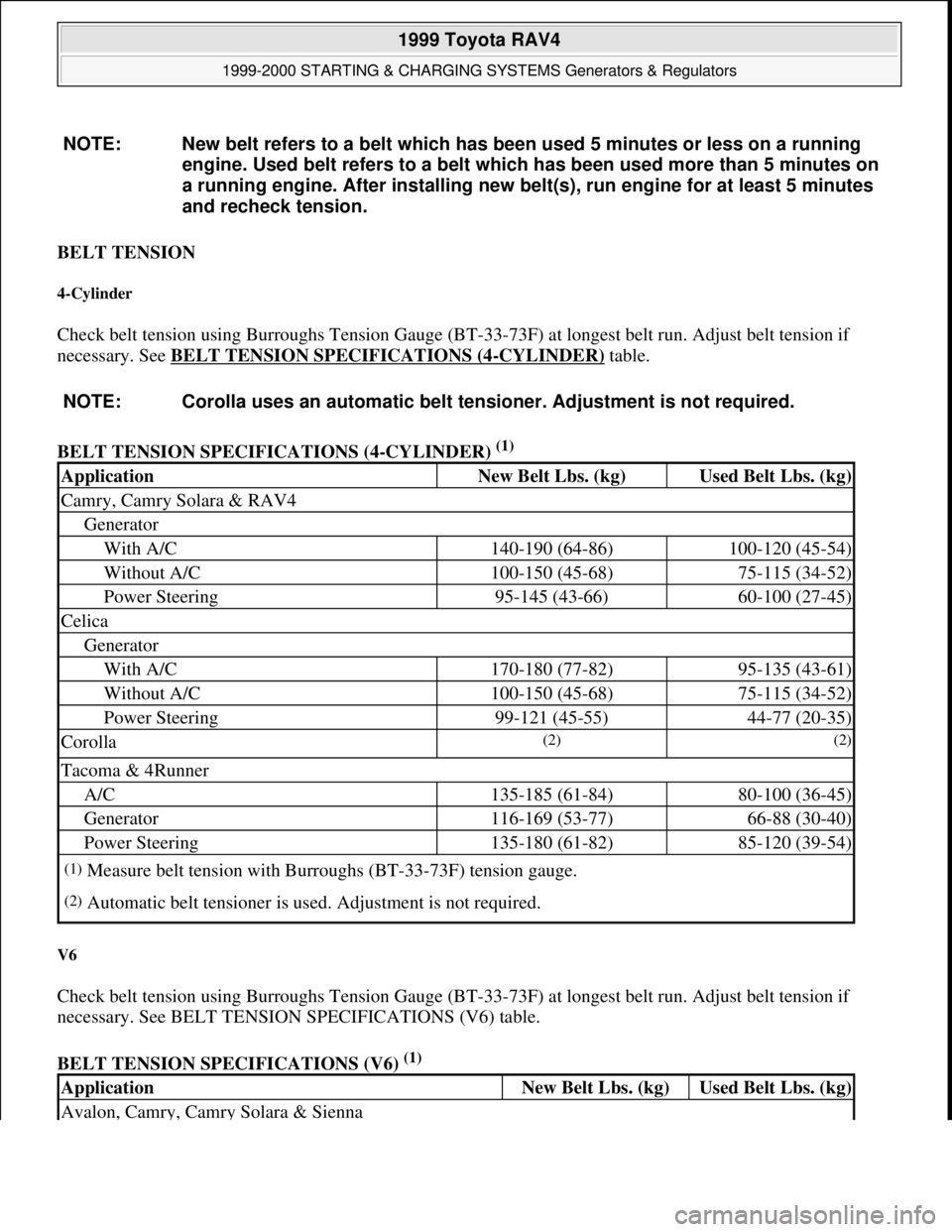
BELT TENSION
4-Cylinder
Check belt tension using Burroughs Tension Gauge (BT-33-73F) at longest belt run. Adjust belt tension if
necessary. See BELT TENSION SPECIFICATIONS (4
-CYLINDER) table.
BELT TENSION SPECIFICATIONS (4-CYLINDER)
(1)
V6
Check belt tension using Burroughs Tension Gauge (BT-33-73F) at longest belt run. Adjust belt tension if
necessary. See BELT TENSION SPECIFICATIONS (V6) table.
BELT TENSION SPECIFICATIONS (V6)
(1) NOTE: New belt refers to a belt which has been used 5 minutes or less on a running
engine. Used belt refers to a belt which has been used more than 5 minutes on
a running engine. After installing new belt(s), run engine for at least 5 minutes
and recheck tension.
NOTE: Corolla uses an automatic belt tensioner. Adjustment is not required.
ApplicationNew Belt Lbs. (kg)Used Belt Lbs. (kg)
Camry, Camry Solara & RAV4
Generator
With A/C140-190 (64-86)100-120 (45-54)
Without A/C100-150 (45-68)75-115 (34-52)
Power Steering95-145 (43-66)60-100 (27-45)
Celica
Generator
With A/C170-180 (77-82)95-135 (43-61)
Without A/C100-150 (45-68)75-115 (34-52)
Power Steering99-121 (45-55)44-77 (20-35)
Corolla(2) (2)
Tacoma & 4Runner
A/C135-185 (61-84)80-100 (36-45)
Generator116-169 (53-77)66-88 (30-40)
Power Steering135-180 (61-82)85-120 (39-54)
(1)Measure belt tension with Burroughs (BT-33-73F) tension gauge.
(2)Automatic belt tensioner is used. Adjustment is not required.
ApplicationNew Belt Lbs. (kg)Used Belt Lbs. (kg)
Avalon, Camry, Camry Solara & Sienna
1999 Toyota RAV4
1999-2000 STARTING & CHARGING SYSTEMS Generators & Regulators
Microsoft
Sunday, November 22, 2009 10:13:07 AMPage 2 © 2005 Mitchell Repair Information Company, LLC.
Page 408 of 1632
exposed brush length is less than minimum, replace brushes or brush holder assembly. Install new brush
springs when replacing brushes.
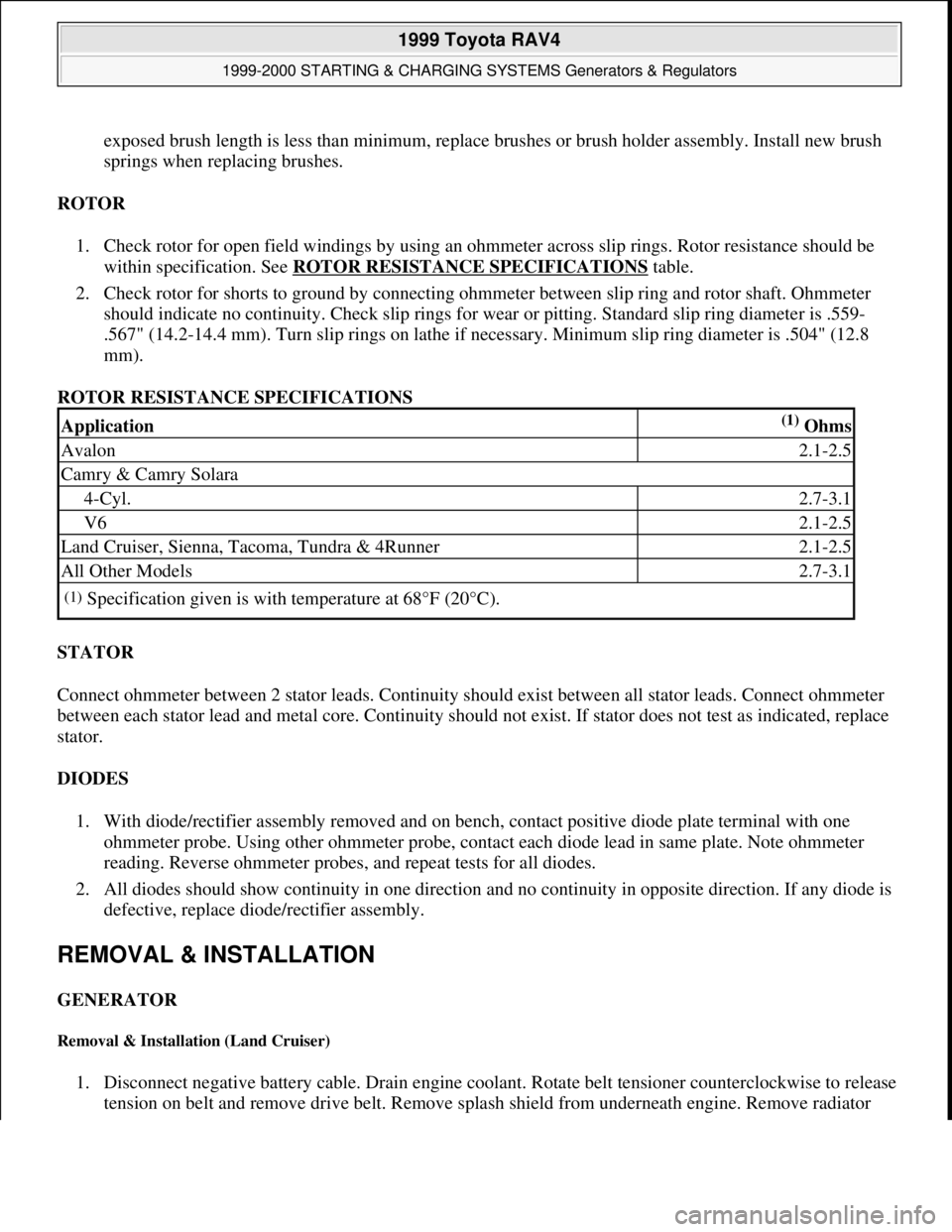
ROTOR
1. Check rotor for open field windings by using an ohmmeter across slip rings. Rotor resistance should be
within specification. See ROTOR RESISTANCE SPECIFICATIONS
table.
2. Check rotor for shorts to ground by connecting ohmmeter between slip ring and rotor shaft. Ohmmeter
should indicate no continuity. Check slip rings for wear or pitting. Standard slip ring diameter is .559-
.567" (14.2-14.4 mm). Turn slip rings on lathe if necessary. Minimum slip ring diameter is .504" (12.8
mm).
ROTOR RESISTANCE SPECIFICATIONS
STATOR
Connect ohmmeter between 2 stator leads. Continuity should exist between all stator leads. Connect ohmmeter
between each stator lead and metal core. Continuity should not exist. If stator does not test as indicated, replace
stator.
DIODES
1. With diode/rectifier assembly removed and on bench, contact positive diode plate terminal with one
ohmmeter probe. Using other ohmmeter probe, contact each diode lead in same plate. Note ohmmeter
reading. Reverse ohmmeter probes, and repeat tests for all diodes.
2. All diodes should show continuity in one direction and no continuity in opposite direction. If any diode is
defective, replace diode/rectifier assembly.
REMOVAL & INSTALLATION
GENERATOR
Removal & Installation (Land Cruiser)
1. Disconnect negative battery cable. Drain engine coolant. Rotate belt tensioner counterclockwise to release
tension on belt and remove drive belt. Remove splash shield from underneath en
gine. Remove radiator
Application(1) Ohms
Avalon2.1-2.5
Camry & Camry Solara
4-Cyl.2.7-3.1
V62.1-2.5
Land Cruiser, Sienna, Tacoma, Tundra & 4Runner2.1-2.5
All Other Models2.7-3.1
(1)Specification given is with temperature at 68°F (20°C).
1999 Toyota RAV4
1999-2000 STARTING & CHARGING SYSTEMS Generators & Regulators
Microsoft
Sunday, November 22, 2009 10:13:07 AMPage 7 © 2005 Mitchell Repair Information Company, LLC.
Page 471 of 1632
1999-2000 ENGINE COOLING
Electric Cooling Fans
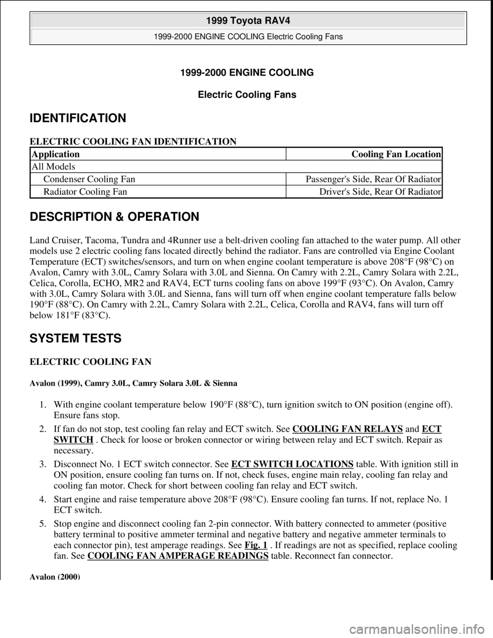
IDENTIFICATION
ELECTRIC COOLING FAN IDENTIFICATION
DESCRIPTION & OPERATION
Land Cruiser, Tacoma, Tundra and 4Runner use a belt-driven cooling fan attached to the water pump. All other
models use 2 electric cooling fans located directly behind the radiator. Fans are controlled via Engine Coolant
Temperature (ECT) switches/sensors, and turn on when engine coolant temperature is above 208°F (98°C) on
Avalon, Camry with 3.0L, Camry Solara with 3.0L and Sienna. On Camry with 2.2L, Camry Solara with 2.2L,
Celica, Corolla, ECHO, MR2 and RAV4, ECT turns cooling fans on above 199°F (93°C). On Avalon, Camry
with 3.0L, Camry Solara with 3.0L and Sienna, fans will turn off when engine coolant temperature falls below
190°F (88°C). On Camry with 2.2L, Camry Solara with 2.2L, Celica, Corolla and RAV4, fans will turn off
below 181°F (83°C).
SYSTEM TESTS
ELECTRIC COOLING FAN
Avalon (1999), Camry 3.0L, Camry Solara 3.0L & Sienna
1. With engine coolant temperature below 190°F (88°C), turn ignition switch to ON position (engine off).
Ensure fans stop.
2. If fan do not stop, test cooling fan relay and ECT switch. See COOLING FAN RELAYS
and ECT
SWITCH . Check for loose or broken connector or wiring between relay and ECT switch. Repair as
necessary.
3. Disconnect No. 1 ECT switch connector. See ECT SWITCH LOCATIONS
table. With ignition still in
ON position, ensure cooling fan turns on. If not, check fuses, engine main relay, cooling fan relay and
cooling fan motor. Check for short between cooling fan relay and ECT switch.
4. Start engine and raise temperature above 208°F (98°C). Ensure cooling fan turns. If not, replace No. 1
ECT switch.
5. Stop engine and disconnect cooling fan 2-pin connector. With battery connected to ammeter (positive
battery terminal to positive ammeter terminal and negative battery and negative ammeter terminals to
each connector pin), test amperage readings. See Fig. 1
. If readings are not as specified, replace cooling
fan. See COOLING FAN AMPERAGE READINGS
table. Reconnect fan connector.
Avalon (2000)
ApplicationCooling Fan Location
All Models
Condenser Cooling FanPassenger's Side, Rear Of Radiator
Radiator Cooling FanDriver's Side, Rear Of Radiator
1999 Toyota RAV4
1999-2000 ENGINE COOLING Electric Cooling Fans
1999 Toyota RAV4
1999-2000 ENGINE COOLING Electric Cooling Fans
Microsoft
Sunday, November 22, 2009 10:21:41 AMPage 1 © 2005 Mitchell Repair Information Company, LLC.
Microsoft
Sunday, November 22, 2009 10:21:45 AMPage 1 © 2005 Mitchell Repair Information Company, LLC.
Page 685 of 1632
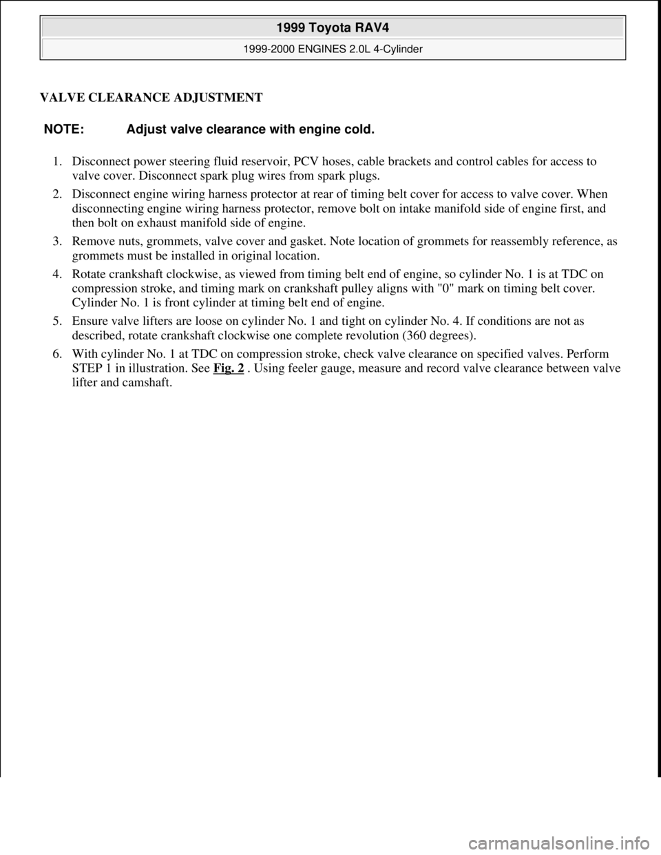
VALVE CLEARANCE ADJUSTMENT
1. Disconnect power steering fluid reservoir, PCV hoses, cable brackets and control cables for access to
valve cover. Disconnect spark plug wires from spark plugs.
2. Disconnect engine wiring harness protector at rear of timing belt cover for access to valve cover. When
disconnecting engine wiring harness protector, remove bolt on intake manifold side of engine first, and
then bolt on exhaust manifold side of engine.
3. Remove nuts, grommets, valve cover and gasket. Note location of grommets for reassembly reference, as
grommets must be installed in original location.
4. Rotate crankshaft clockwise, as viewed from timing belt end of engine, so cylinder No. 1 is at TDC on
compression stroke, and timing mark on crankshaft pulley aligns with "0" mark on timing belt cover.
Cylinder No. 1 is front cylinder at timing belt end of engine.
5. Ensure valve lifters are loose on cylinder No. 1 and tight on cylinder No. 4. If conditions are not as
described, rotate crankshaft clockwise one complete revolution (360 degrees).
6. With cylinder No. 1 at TDC on compression stroke, check valve clearance on specified valves. Perform
STEP 1 in illustration. See Fig. 2
. Using feeler gauge, measure and record valve clearance between valve
lifter and camshaft. NOTE: Adjust valve clearance with engine cold.
1999 Toyota RAV4
1999-2000 ENGINES 2.0L 4-Cylinder
Microsoft
Sunday, November 22, 2009 10:22:26 AMPage 2 © 2005 Mitchell Repair Information Company, LLC.
Page 701 of 1632

Removal
1. Release fuel pressure. See FUEL PRESSURE RELEASE . Drain cooling system. Raise and support
vehicle. Remove right lower engine cover.
2. Disconnect control cables at throttle body. Remove air cleaner assembly and air cleaner case. Remove
accessory drive belt and generator.
3. Remove front exhaust pipe. Remove exhaust manifold and heat insulator assembly. Disconnect oxygen
sensor (except California) or Air/Fuel (A/F) ratio sensor (California), and remove exhaust manifold and
heat shield. Remove sensors from exhaust manifold and front catalytic converter, if equipped.
4. Remove heat insulator from front exhaust pipe. Remove throttle body and gasket. Remove ignition coils
with spark plug wires attached.
5. Disconnect necessary electrical connectors, coolant hoses and vacuum hoses from cylinder head and
intake manifold. Remove coolant outlet, coolant by-pass pipe and gaskets.
6. Disconnect hoses and ground strap. Remove union bolt, and disconnect fuel line at fuel filter. Remove
EGR valve and vacuum modulator. Disconnect power steering idle-up hoses from air tube.
7. Remove 2 bolts and accelerator cable bracket. Disconnect PCV hoses, cable brackets and control cables
for access to valve cover. Disconnect engine wiring harness protector at rear of timing belt cover for
access to valve cover. Remove nuts, grommets, valve cover and gasket. Note location of grommets for
reassembly reference, as grommets must be installed in original location.
8. Remove bolts, and disconnect engine wiring harness protector from left side of intake manifold.
Disconnect electrical connectors at injectors, A/C compressor and crankshaft position sensor. Remove
engine wiring harness clamps from timing belt cover and generator drive belt adjusting bar.
9. Remove scuff plate from passenger-side door opening and passenger-side kick panel. Remove right side
cowl side trim and floor carpet center cover. Disconnect 2 electrical connectors from Engine Control
Module (ECM), and 2 electrical connectors on bracket. See Fig. 9
. Disconnect electrical connector for
relay box located behind passenger-side kick panel.
10. Disconnect engine wiring harness clamp located on engine wiring, near firewall. Pull engine wiring
harness out through firewall. Remove engine wiring harness from between cylinder head and intake
manifold.
11. Disconnect timing belt from camshaft timing pulley. Remove camshaft timing pulley. Remove No. 1 idler
pulley and tension spring. See TIMING BELT
. Remove 3 bolts and timing belt cover. See Fig. 14 .
After removing timing belt from camshaft sprocket, support timing belt so belt does not come off
crankshaft sprocket.
1999 Toyota RAV4
1999-2000 ENGINES 2.0L 4-Cylinder
Microsoft
Sunday, November 22, 2009 10:22:26 AMPage 18 © 2005 Mitchell Repair Information Company, LLC.
Page 704 of 1632
Inspection
1. Inspect cylinder head warpage at cylinder block, exhaust manifold and intake manifold surfaces. Replace
cylinder head if warpage exceeds specification. See CYLINDER HEAD
table under ENGINE
SPECIFICATIONS.
2. Inspect cylinder block deck surface for warpage. Replace cylinder block if deck surface warpage exceeds
specification. See CYLINDER BLOCK
table under ENGINE SPECIFICATIONS.
3. Inspect intake and exhaust manifold machined surfaces for warpage. Replace component if warpage
exceeds .0118" (.300 mm). Inspect camshaft and components. See CAMSHAFT
.
4. Measure valve lifter diameter and bore diameter. Ensure oil clearance is within specification. Replace
components if not within specification. See VALVE LIFTERS
table under ENGINE
SPECIFICATIONS.
Installation
1. Apply adhesive to 2 or 3 threads of oil pressure switch, and install switch. Install NEW insulator at
bottom of fuel injector and NEW grommet on top of fuel injector. Coat NEW "O" rings with gasoline and
install on fuel injector.
2. Install 2 spacers on cylinder head. Install fuel injectors on cylinder head. Install fuel delivery pipe on fuel
injectors. Using twisting motion, push fuel injectors into fuel delivery pipe.
3. Install and slightly tighten fuel delivery pipe-to-cylinder head bolts. Ensure all fuel injectors rotate
smoothly. If fuel injector fails to rotate smoothly, check for improperly installed or damaged "O" rings.
4. Position electrical connector on fuel injector facing toward top of engine. Tighten fuel delivery pipe-to-
cylinder head bolts to specification. See TORQUE SPECIFICATIONS
.
5. Using NEW gasket, install intake manifold. Install and tighten bolts/nuts to specification. See TORQUE
SPECIFICATIONS . Install air tube on side of intake manifold.
6. Install adjusting shims and valve lifters in original location on cylinder head (if removed). Ensure valve
lifters rotate smoothly in cylinder head.
7. Install NEW gasket for cylinder head on cylinder block. Ensure all holes in gasket align with holes in
cylinder block.
8. Install cylinder head. Coat threads and bolt-to-cylinder contact surfaces on cylinder head bolts with
engine oil. Install and tighten cylinder head bolts in several steps, to specification in sequence. See Fig.
15 . See TORQUE SPECIFICATIONS .
9. If removed, install spark plug tubes. Install camshafts using proper procedure. See CAMSHAFT
. Install
No. 3 timing belt cover. Install and tighten bolts to specification. See TORQUE SPECIFICATIONS
.
10. To install remaining components, reverse removal procedure. If camshaft or cylinder head components
are serviced, adjust valve clearance. See VALVE CLEARANCE ADJUSTMENT
under
ADJUSTMENTS.
11. Before installing gasket and valve cover, apply sealant at front and rear valve cover areas on cylinder
head. See Fig. 6
. Using NEW gasket, install valve cover.
12. Install grommets in original location with marking on grommet aligned in designated area. See Fig. 7
.
Install and tighten valve cover nuts to specification. See TORQUE SPECIFICATIONS
.
13. Install VSV for EGR. Connect ground cable to intake manifold with bolt. Connect knock sensor
connector. Connect power steerin
g idle-up air hoses to air tube. On A/T models, connect A/T throttle
1999 Toyota RAV4
1999-2000 ENGINES 2.0L 4-Cylinder
Microsoft
Sunday, November 22, 2009 10:22:26 AMPage 21 © 2005 Mitchell Repair Information Company, LLC.
Page 705 of 1632
control cable to intake manifold. On all models, install NEW gasket and EGR valve with union nut and 2
nuts. Install vacuum modulator to clamp on intake manifold. Connect vacuum hoses to EGR VSV.
Connect fuel inlet hose to fuel filter
14. Connect vacuum sensor hose to gas filter, and brake booster vacuum hose to intake manifold. Install
throttle body. Install NEW "O" ring on coolant by-pass pipe, and NEW gasket on water pump cover
before installing coolant by-pass pipe. Apply soapy water solution to "O" ring before installing coolant
by-pass pipe. Install by-pass pipe.
15. Install NEW gasket and water outlet. Connect radiator, water by-pass and heater water hoses. Connect
ECT sensor and sender gauge connectors. Connect oil pressure switch.
16. Install ignition coils, manifold stay and spark plug wires. Connect wire clamp to manifold stay. Connect
spark plug wires to spark plugs and clamps on cylinder head cover. Connect ignition coil connectors.
17. Install 2 heat insulators. Install lower heat insulator. On California models, install A/F sensor to exhaust
manifold. All others, install oxygen sensor (bank 1 sensor 1) to exhaust manifold.
18. Using a new gasket, install exhaust manifold and heat insulator assembly. Install right-side exhaust
manifolds stay (California). Install left-side exhaust manifold stay. Install upper manifold heat insulator.
Connect A/F sensor connectors (California), or Oxygen sensor (bank 1 sensor 1).
19. Use NEW gasket and NEW nuts when installing front exhaust pipe. Ensure all bolts/nuts are loosely
installed on front exhaust pipe before tightening to specification. See TORQUE SPECIFICATIONS
20. Install generator and air cleaner and cap. Connect accelerator cable to throttle body and cable bracket. On
A/T models, connect throttle cable to throttle body and cable bracket. On all models, start engine and
check for leaks. Recheck engine coolant and oil level. Install right-side engine undercover.
CRANKSHAFT FRONT SEAL
Removal & Installation (Oil Pump Installed)
1. Remove timing belt and crankshaft sprocket. See TIMING BELT . Using a knife, cut lip from seal. Pry
seal from oil pump housing. DO NOT damage sealing surfaces.
2. To install, apply grease to lip of new seal. Using hammer and Seal Installer (SST 09226-10010), install
seal until seal surface is even with oil pump housing. To install remaining components, reverse removal
procedure.
Removal & Installation (Oil Pump Removed)
Using hammer and drift, remove seal from oil pump housing. To install, use hammer and Seal Installer (SST
09226-10010). Install seal until seal surface is even with oil pump housing. Apply grease to lip of new seal.
TIMING BELT
CAUTION: If reusing timing belt, mark direction of timing belt rotation, and place
reference mark on timing belt at camshaft sprocket for reassembly
reference. Also, place reference mark on timing belt at upper edge of No. 1
timing belt cover. DO NOT bend, twist or turn timing belt inside-out. DO
NOT expose timing to oil, water or steam.
1999 Toyota RAV4
1999-2000 ENGINES 2.0L 4-Cylinder
Microsoft
Sunday, November 22, 2009 10:22:26 AMPage 22 © 2005 Mitchell Repair Information Company, LLC.
Page 707 of 1632
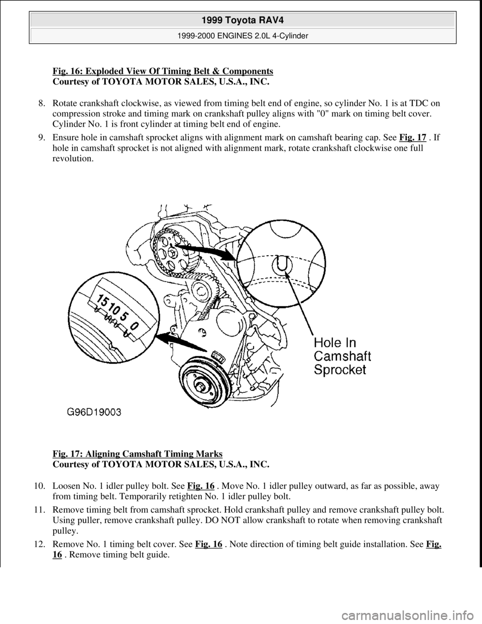
Fig. 16: Exploded View Of Timing Belt & Components
Courtesy of TOYOTA MOTOR SALES, U.S.A., INC.
8. Rotate crankshaft clockwise, as viewed from timing belt end of engine, so cylinder No. 1 is at TDC on
compression stroke and timing mark on crankshaft pulley aligns with "0" mark on timing belt cover.
Cylinder No. 1 is front cylinder at timing belt end of engine.
9. Ensure hole in camshaft sprocket aligns with alignment mark on camshaft bearing cap. See Fig. 17
. If
hole in camshaft sprocket is not aligned with alignment mark, rotate crankshaft clockwise one full
revolution.
Fig. 17: Aligning Camshaft Timing Marks
Courtesy of TOYOTA MOTOR SALES, U.S.A., INC.
10. Loosen No. 1 idler pulley bolt. See Fig. 16
. Move No. 1 idler pulley outward, as far as possible, away
from timing belt. Temporarily retighten No. 1 idler pulley bolt.
11. Remove timing belt from camshaft sprocket. Hold crankshaft pulley and remove crankshaft pulley bolt.
Using puller, remove crankshaft pulley. DO NOT allow crankshaft to rotate when removing crankshaft
pulley.
12. Remove No. 1 timing belt cover. See Fig. 16
. Note direction of timing belt guide installation. See Fig.
16 . Remove timing belt guide.
1999 Toyota RAV4
1999-2000 ENGINES 2.0L 4-Cylinder
Microsoft
Sunday, November 22, 2009 10:22:26 AMPage 24 © 2005 Mitchell Repair Information Company, LLC.
Page 708 of 1632
13. If reusing timing belt, mark direction of timing belt rotation and place reference marks on timing belt and
crankshaft sprocket for reassembly reference. Remove timing belt from crankshaft sprocket.
14. Remove idler pulleys (if necessary). If removing camshaft sprocket, use spanner wrench to hold camshaft
sprocket and remove camshaft sprocket bolt. Remove camshaft sprocket.
15. If removing crankshaft sprocket, use puller to pull crankshaft sprocket from crankshaft. If removing oil
pump sprocket, hold oil pump sprocket by installing spanner wrench in holes on front of oil pump
sprocket. Remove oil pump sprocket nut. Remove spanner wrench and oil pump sprocket.
Inspection
1. Inspect timing belt for damaged teeth, cracking or oil contamination. Ensure idler pulleys rotate freely.
Replace components if damaged or worn.
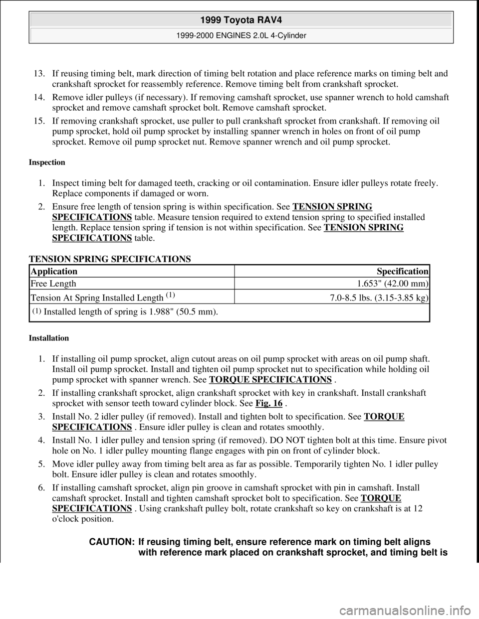
2. Ensure free length of tension spring is within specification. See TENSION SPRING
SPECIFICATIONS table. Measure tension required to extend tension spring to specified installed
length. Replace tension spring if tension is not within specification. See TENSION SPRING
SPECIFICATIONS table.
TENSION SPRING SPECIFICATIONS
Installation
1. If installing oil pump sprocket, align cutout areas on oil pump sprocket with areas on oil pump shaft.
Install oil pump sprocket. Install and tighten oil pump sprocket nut to specification while holding oil
pump sprocket with spanner wrench. See TORQUE SPECIFICATIONS
.
2. If installing crankshaft sprocket, align crankshaft sprocket with key in crankshaft. Install crankshaft
sprocket with sensor teeth toward cylinder block. See Fig. 16
.
3. Install No. 2 idler pulley (if removed). Install and tighten bolt to specification. See TORQUE
SPECIFICATIONS . Ensure idler pulley is clean and rotates smoothly.
4. Install No. 1 idler pulley and tension spring (if removed). DO NOT tighten bolt at this time. Ensure pivot
hole on No. 1 idler pulley mounting flange engages with pin on front of cylinder block.
5. Move idler pulley away from timing belt area as far as possible. Temporarily tighten No. 1 idler pulley
bolt. Ensure idler pulley is clean and rotates smoothly.
6. If installing camshaft sprocket, align pin groove in camshaft sprocket with pin in camshaft. Install
camshaft sprocket. Install and tighten camshaft sprocket bolt to specification. See TORQUE
SPECIFICATIONS . Using crankshaft pulley bolt, rotate crankshaft so key on crankshaft is at 12
o'clock position.
ApplicationSpecification
Free Length1.653" (42.00 mm)
Tension At Spring Installed Length (1) 7.0-8.5 lbs. (3.15-3.85 kg)
(1)Installed length of spring is 1.988" (50.5 mm).
CAUTION: If reusing timing belt, ensure reference mark on timing belt aligns
with reference mark placed on crankshaft sprocket, and timing belt is
1999 Toyota RAV4
1999-2000 ENGINES 2.0L 4-Cylinder
Microsoft
Sunday, November 22, 2009 10:22:26 AMPage 25 © 2005 Mitchell Repair Information Company, LLC.
Page 709 of 1632
7. Ensure all sprockets and idler pulleys are clean. Install timing belt on crankshaft sprocket, oil pump
sprocket, water pump sprocket, No. 1 idler pulley and then No. 2 idler pulley.
8. Install timing belt guide with cupped side away from crankshaft sprocket and flat side toward timing belt.
Install No. 1 timing belt cover.
9. Remove crankshaft pulley bolt. Align crankshaft pulley key groove with key in crankshaft. Install
crankshaft pulley. Temporarily install and tighten crankshaft pulley bolt.
10. If using new timing belt, go to step 15 . If reusing timing belt, ensure reference mark placed on timing
belt aligns with upper edge of No. 1 timing belt cover when timing mark on crankshaft pulley aligns with
"0" mark on No. 1 timing belt cover. If reference mark is aligned, proceed to step 15 .
11. If reference mark is below surface of No. 1 timing belt cover, pull upward on water pump side of timing
belt while rotating crankshaft pulley counterclockwise. Align reference mark with surface of No. 1 timing
belt cover.
12. After aligning matchmark, hold timing belt and rotate crankshaft pulley clockwise so timing mark on
crankshaft pulley aligns with "0" mark on No. 1 timing belt cover.
13. If reference mark is above surface of No. 1 timing belt cover, pull upward on No. 1 idler pulley side of
timing belt while rotating crankshaft pulley clockwise. Align reference mark with surface of No. 1 timing
belt cover.
14. After aligning matchmark, hold timing belt and rotate crankshaft pulley counterclockwise so timing mark
on crankshaft pulley aligns with "0" mark on No. 1 timing belt cover.
15. Install timing belt on camshaft sprocket. If reusing timing belt, ensure reference mark on timing belt
aligns with reference mark placed on camshaft sprocket. Ensure tension exists on timing belt between
crankshaft and camshaft sprockets.
16. Loosen No. 1 idler pulley bolt 1/2 turn. Rotate crankshaft pulley 2 full revolutions clockwise from TDC
to TDC. DO NOT rotate crankshaft counterclockwise.
17. Ensure timing mark on crankshaft pulley aligns with "0" mark on No. 1 timing belt cover, and hole in
camshaft sprocket aligns with alignment mark on camshaft bearing cap. See Fig. 17
. If timing marks are
not aligned, remove timing belt and reinstall.
18. Rotate crankshaft clockwise 1 7/8 revolutions and align crankshaft pulley "0" mark with 45-degree
Before Top Dead Center (BTDC) mark on No. 1 timin
g belt cover. See Fig. 18 . installed in original direction of rotation.
1999 Toyota RAV4
1999-2000 ENGINES 2.0L 4-Cylinder
Microsoft
Sunday, November 22, 2009 10:22:26 AMPage 26 © 2005 Mitchell Repair Information Company, LLC.