coolant level TOYOTA RAV4 1996 Service Repair Manual
[x] Cancel search | Manufacturer: TOYOTA, Model Year: 1996, Model line: RAV4, Model: TOYOTA RAV4 1996Pages: 1632, PDF Size: 41.64 MB
Page 676 of 1632

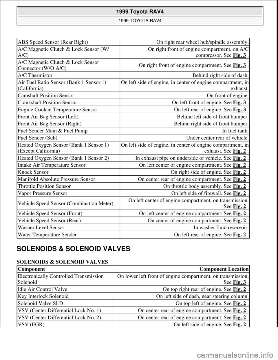
SOLENOIDS & SOLENOID VALVES
SOLENOIDS & SOLENOID VALVES
ABS Speed Sensor (Rear Right)On right rear wheel hub/spindle assembly.
A/C Magnetic Clutch & Lock Sensor (W/
A/C)On right front of engine compartment, on A/C
compressor. See Fig. 3
.
A/C Magnetic Clutch & Lock Sensor
Connector (W/O A/C)On right front of engine compartment. See Fig. 3 .
A/C ThermistorBehind right side of dash.
Air Fuel Ratio Sensor (Bank 1 Sensor 1)
(California)On left side of engine, in center of engine compartment, in
exhaust.
Camshaft Position SensorOn front of engine.
Crankshaft Position SensorOn left front of engine. See Fig. 3 .
Engine Coolant Temperature SensorOn left rear of engine. See Fig. 3 .
Front Air Bag Sensor (Left)Behind left side of front bumper.
Front Air Bag Sensor (Right)Behind right side of front bumper.
Fuel Sender Main & Fuel PumpIn fuel tank.
Fuel Sender (Sub)Under center rear of vehicle.
Heated Oxygen Sensor (Bank 1 Sensor 1)
(Except California)On left side of engine, in center of engine compartment, in
exhaust. See Fig. 2
.
Heated Oxygen Sensor (Bank 1 Sensor 2)In exhaust pipe on underside of vehicle. See Fig. 2 .
Intake Air Temperature SensorOn left center of engine compartment. See Fig. 2 .
Knock SensorOn right side of engine. See Fig. 2 .
Manifold Absolute Pressure SensorOn center rear of engine compartment. See Fig. 2 .
Throttle Position SensorOn throttle body assembly. See Fig. 2 .
Vapor Pressure SensorOn left side of firewall. See Fig. 2 .
Vehicle Speed Sensor (Combination Meter)On left center of engine compartment, on transmission.
See Fig. 2
.
Vehicle Speed Sensor (Front)On left center of engine compartment. See Fig. 2 .
Vehicle Speed Sensor (Rear)On center of engine compartment. See Fig. 2 .
Washer Level SensorIn washer fluid reservoir.
Water Temperature SenderOn left rear of engine. See Fig. 2 .
ComponentComponent Location
Electronically Controlled Transmission
SolenoidOn lower left front of engine compartment, on transmission.
See Fig. 3
.
Idle Air Control ValveOn top right rear of engine. See Fig. 2 .
Key Interlock SolenoidOn left side of dash, near steering column.
Solenoid Valve SLDOn top left of engine. See Fig. 2 .
VSV (Center Differential Lock No. 1)On center rear of engine compartment. See Fig. 2 .
VSV (Center Differential Lock No. 2)On center rear of engine compartment. See Fig. 2 .
VSV (EGR)On left side of engine. See Fig. 2 .
1999 Toyota RAV4
1999 TOYOTA RAV4
Microsoft
Sunday, November 22, 2009 10:17:32 AMPage 3 © 2005 Mitchell Repair Information Company, LLC.
Page 705 of 1632

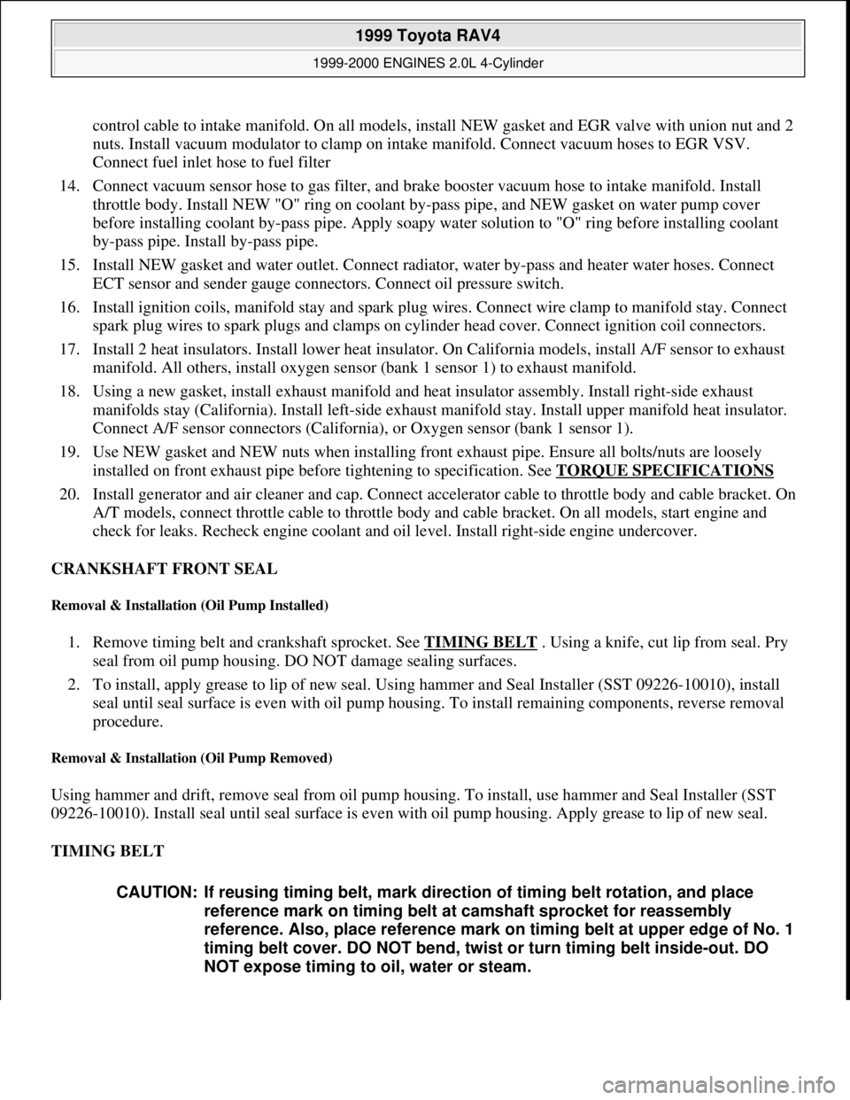
control cable to intake manifold. On all models, install NEW gasket and EGR valve with union nut and 2
nuts. Install vacuum modulator to clamp on intake manifold. Connect vacuum hoses to EGR VSV.
Connect fuel inlet hose to fuel filter
14. Connect vacuum sensor hose to gas filter, and brake booster vacuum hose to intake manifold. Install
throttle body. Install NEW "O" ring on coolant by-pass pipe, and NEW gasket on water pump cover
before installing coolant by-pass pipe. Apply soapy water solution to "O" ring before installing coolant
by-pass pipe. Install by-pass pipe.
15. Install NEW gasket and water outlet. Connect radiator, water by-pass and heater water hoses. Connect
ECT sensor and sender gauge connectors. Connect oil pressure switch.
16. Install ignition coils, manifold stay and spark plug wires. Connect wire clamp to manifold stay. Connect
spark plug wires to spark plugs and clamps on cylinder head cover. Connect ignition coil connectors.
17. Install 2 heat insulators. Install lower heat insulator. On California models, install A/F sensor to exhaust
manifold. All others, install oxygen sensor (bank 1 sensor 1) to exhaust manifold.
18. Using a new gasket, install exhaust manifold and heat insulator assembly. Install right-side exhaust
manifolds stay (California). Install left-side exhaust manifold stay. Install upper manifold heat insulator.
Connect A/F sensor connectors (California), or Oxygen sensor (bank 1 sensor 1).
19. Use NEW gasket and NEW nuts when installing front exhaust pipe. Ensure all bolts/nuts are loosely
installed on front exhaust pipe before tightening to specification. See TORQUE SPECIFICATIONS
20. Install generator and air cleaner and cap. Connect accelerator cable to throttle body and cable bracket. On
A/T models, connect throttle cable to throttle body and cable bracket. On all models, start engine and
check for leaks. Recheck engine coolant and oil level. Install right-side engine undercover.
CRANKSHAFT FRONT SEAL
Removal & Installation (Oil Pump Installed)
1. Remove timing belt and crankshaft sprocket. See TIMING BELT . Using a knife, cut lip from seal. Pry
seal from oil pump housing. DO NOT damage sealing surfaces.
2. To install, apply grease to lip of new seal. Using hammer and Seal Installer (SST 09226-10010), install
seal until seal surface is even with oil pump housing. To install remaining components, reverse removal
procedure.
Removal & Installation (Oil Pump Removed)
Using hammer and drift, remove seal from oil pump housing. To install, use hammer and Seal Installer (SST
09226-10010). Install seal until seal surface is even with oil pump housing. Apply grease to lip of new seal.
TIMING BELT
CAUTION: If reusing timing belt, mark direction of timing belt rotation, and place
reference mark on timing belt at camshaft sprocket for reassembly
reference. Also, place reference mark on timing belt at upper edge of No. 1
timing belt cover. DO NOT bend, twist or turn timing belt inside-out. DO
NOT expose timing to oil, water or steam.
1999 Toyota RAV4
1999-2000 ENGINES 2.0L 4-Cylinder
Microsoft
Sunday, November 22, 2009 10:22:26 AMPage 22 © 2005 Mitchell Repair Information Company, LLC.
Page 948 of 1632

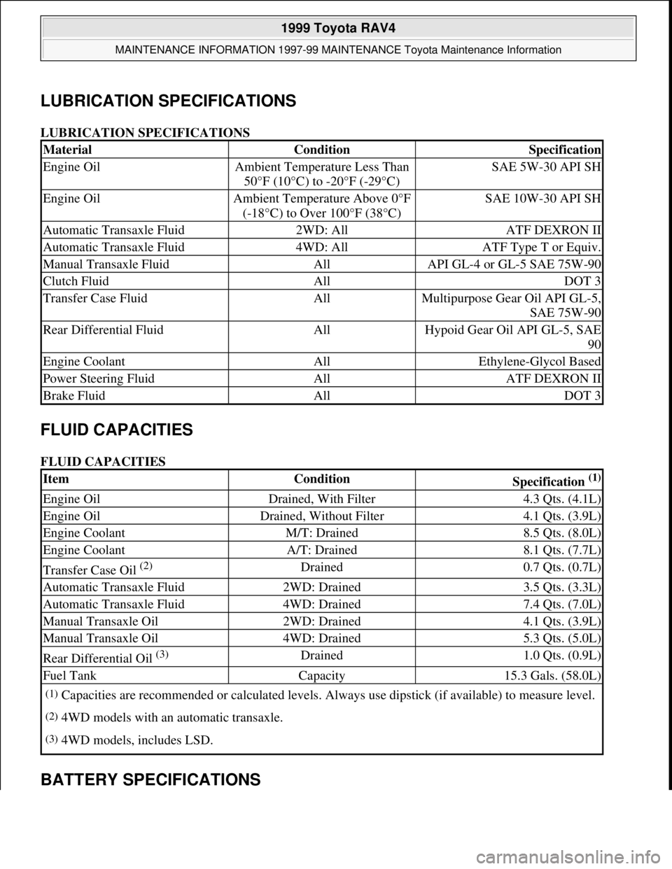
LUBRICATION SPECIFICATIONS
LUBRICATION SPECIFICATIONS
FLUID CAPACITIES
FLUID CAPACITIES
BATTERY SPECIFICATIONS
MaterialConditionSpecification
Engine OilAmbient Temperature Less Than
50°F (10°C) to -20°F (-29°C)SAE 5W-30 API SH
Engine OilAmbient Temperature Above 0°F
(-18°C) to Over 100°F (38°C)SAE 10W-30 API SH
Automatic Transaxle Fluid2WD: AllATF DEXRON II
Automatic Transaxle Fluid4WD: AllATF Type T or Equiv.
Manual Transaxle FluidAllAPI GL-4 or GL-5 SAE 75W-90
Clutch FluidAllDOT 3
Transfer Case FluidAllMultipurpose Gear Oil API GL-5,
SAE 75W-90
Rear Differential FluidAllHypoid Gear Oil API GL-5, SAE
90
Engine CoolantAllEthylene-Glycol Based
Power Steering FluidAllATF DEXRON II
Brake FluidAllDOT 3
ItemConditionSpecification (1)
Engine OilDrained, With Filter4.3 Qts. (4.1L)
Engine OilDrained, Without Filter4.1 Qts. (3.9L)
Engine CoolantM/T: Drained8.5 Qts. (8.0L)
Engine CoolantA/T: Drained8.1 Qts. (7.7L)
Transfer Case Oil (2) Drained0.7 Qts. (0.7L)
Automatic Transaxle Fluid2WD: Drained3.5 Qts. (3.3L)
Automatic Transaxle Fluid4WD: Drained7.4 Qts. (7.0L)
Manual Transaxle Oil2WD: Drained4.1 Qts. (3.9L)
Manual Transaxle Oil4WD: Drained5.3 Qts. (5.0L)
Rear Differential Oil (3) Drained1.0 Qts. (0.9L)
Fuel TankCapacity15.3 Gals. (58.0L)
(1)Capacities are recommended or calculated levels. Always use dipstick (if available) to measure level.
(2)4WD models with an automatic transaxle.
(3)4WD models, includes LSD.
1999 Toyota RAV4
MAINTENANCE INFORMATION 1997-99 MAINTENANCE Toyota Maintenance Information
Microsoft
Sunday, November 22, 2009 10:32:42 AMPage 6 © 2005 Mitchell Repair Information Company, LLC.