differential TOYOTA RAV4 1996 Service Repair Manual
[x] Cancel search | Manufacturer: TOYOTA, Model Year: 1996, Model line: RAV4, Model: TOYOTA RAV4 1996Pages: 1632, PDF Size: 41.64 MB
Page 135 of 1632
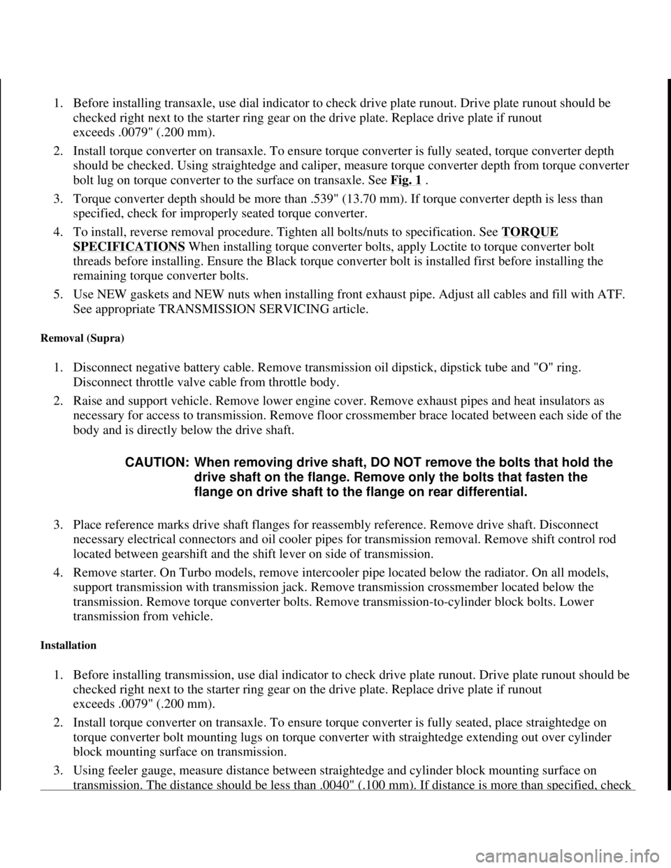
1. Before installing transaxle, use dial indicator to check drive plate runout. Drive plate runout should be
checked right next to the starter ring gear on the drive plate. Replace drive plate if runout
exceeds .0079" (.200 mm).
2. Install torque converter on transaxle. To ensure torque converter is fully seated, torque converter depth
should be checked. Using straightedge and caliper, measure torque converter depth from torque converter
bolt lug on torque converter to the surface on transaxle. See Fig. 1
.
3. Torque converter depth should be more than .539" (13.70 mm). If torque converter depth is less than
specified, check for improperly seated torque converter.
4. To install, reverse removal procedure. Tighten all bolts/nuts to specification. See TORQUE
SPECIFICATIONS When installing torque converter bolts, apply Loctite to torque converter bolt
threads before installing. Ensure the Black torque converter bolt is installed first before installing the
remaining torque converter bolts.
5. Use NEW gaskets and NEW nuts when installing front exhaust pipe. Adjust all cables and fill with ATF.
See appropriate TRANSMISSION SERVICING article.
Removal (Supra)
1. Disconnect negative battery cable. Remove transmission oil dipstick, dipstick tube and "O" ring.
Disconnect throttle valve cable from throttle body.
2. Raise and support vehicle. Remove lower engine cover. Remove exhaust pipes and heat insulators as
necessary for access to transmission. Remove floor crossmember brace located between each side of the
body and is directly below the drive shaft.
3. Place reference marks drive shaft flanges for reassembly reference. Remove drive shaft. Disconnect
necessary electrical connectors and oil cooler pipes for transmission removal. Remove shift control rod
located between gearshift and the shift lever on side of transmission.
4. Remove starter. On Turbo models, remove intercooler pipe located below the radiator. On all models,
support transmission with transmission jack. Remove transmission crossmember located below the
transmission. Remove torque converter bolts. Remove transmission-to-cylinder block bolts. Lower
transmission from vehicle.
Installation
1. Before installing transmission, use dial indicator to check drive plate runout. Drive plate runout should be
checked right next to the starter ring gear on the drive plate. Replace drive plate if runout
exceeds .0079" (.200 mm).
2. Install torque converter on transaxle. To ensure torque converter is fully seated, place straightedge on
torque converter bolt mounting lugs on torque converter with straightedge extending out over cylinder
block mounting surface on transmission.
3. Using feeler gauge, measure distance between straightedge and cylinder block mounting surface on
transmission. The distance should be less than .0040" (.100 mm). If distance is more than specified, check CAUTION: When removing drive shaft, DO NOT remove the bolts that hold the
drive shaft on the flange. Remove only the bolts that fasten the
flange on drive shaft to the flange on rear differential.
1998 Toyota Avalon XLS
TRANSMISSION SERVICING - A/T 1997-98 TRANSMISSION SERVICING Toyota - Transmission Removal &
Installation
Helpmelearn
November-03-08 10:30:29 AMPage 23 © 2005 Mitchell Repair Information Company, LLC.
Page 137 of 1632
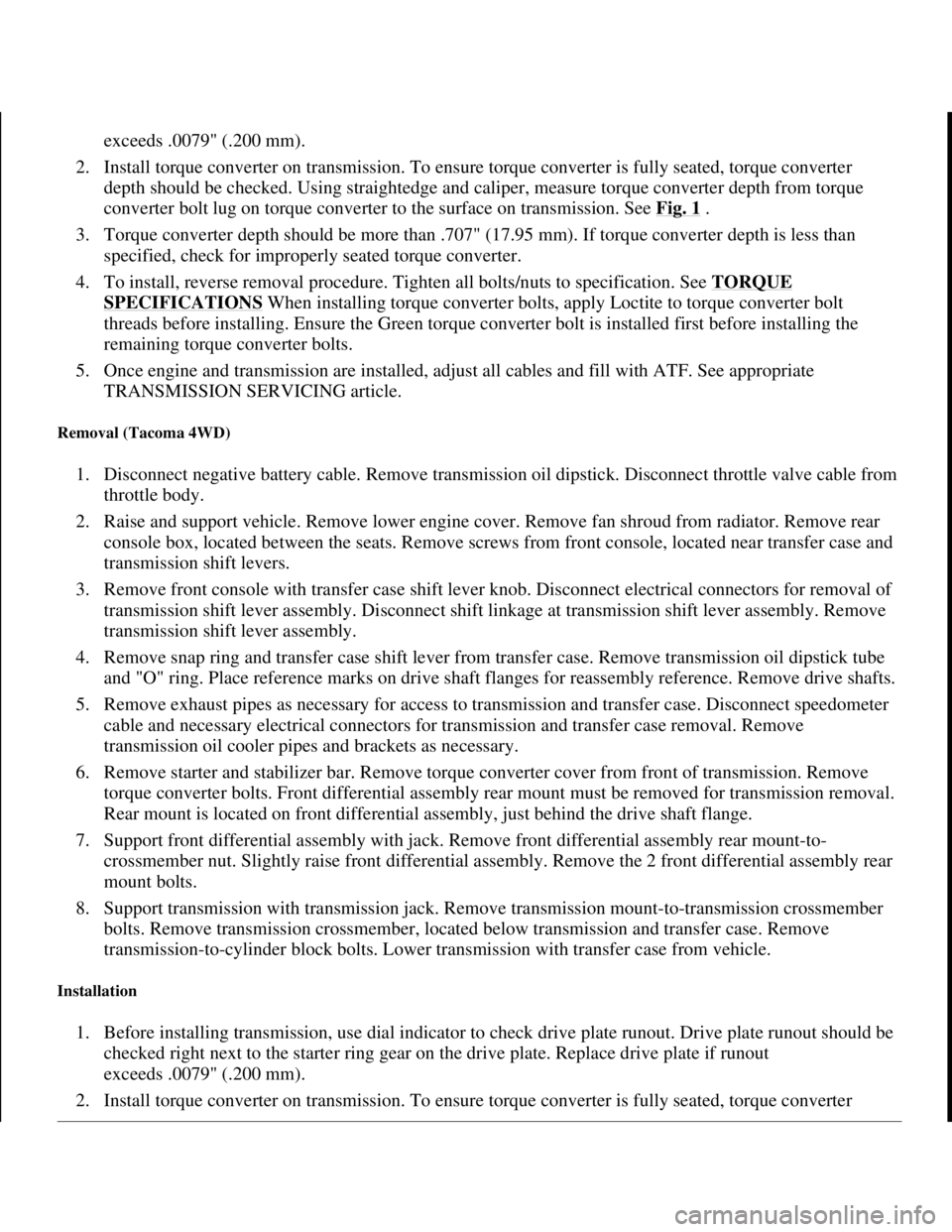
exceeds .0079" (.200 mm).
2. Install torque converter on transmission. To ensure torque converter is fully seated, torque converter
depth should be checked. Using straightedge and caliper, measure torque converter depth from torque
converter bolt lug on torque converter to the surface on transmission. See Fig. 1
.
3. Torque converter depth should be more than .707" (17.95 mm). If torque converter depth is less than
specified, check for improperly seated torque converter.
4. To install, reverse removal procedure. Tighten all bolts/nuts to specification. See TORQUE
SPECIFICATIONS When installing torque converter bolts, apply Loctite to torque converter bolt
threads before installing. Ensure the Green torque converter bolt is installed first before installing the
remaining torque converter bolts.
5. Once engine and transmission are installed, adjust all cables and fill with ATF. See appropriate
TRANSMISSION SERVICING article.
Removal (Tacoma 4WD)
1. Disconnect negative battery cable. Remove transmission oil dipstick. Disconnect throttle valve cable from
throttle body.
2. Raise and support vehicle. Remove lower engine cover. Remove fan shroud from radiator. Remove rear
console box, located between the seats. Remove screws from front console, located near transfer case and
transmission shift levers.
3. Remove front console with transfer case shift lever knob. Disconnect electrical connectors for removal of
transmission shift lever assembly. Disconnect shift linkage at transmission shift lever assembly. Remove
transmission shift lever assembly.
4. Remove snap ring and transfer case shift lever from transfer case. Remove transmission oil dipstick tube
and "O" ring. Place reference marks on drive shaft flanges for reassembly reference. Remove drive shafts.
5. Remove exhaust pipes as necessary for access to transmission and transfer case. Disconnect speedometer
cable and necessary electrical connectors for transmission and transfer case removal. Remove
transmission oil cooler pipes and brackets as necessary.
6. Remove starter and stabilizer bar. Remove torque converter cover from front of transmission. Remove
torque converter bolts. Front differential assembly rear mount must be removed for transmission removal.
Rear mount is located on front differential assembly, just behind the drive shaft flange.
7. Support front differential assembly with jack. Remove front differential assembly rear mount-to-
crossmember nut. Slightly raise front differential assembly. Remove the 2 front differential assembly rear
mount bolts.
8. Support transmission with transmission jack. Remove transmission mount-to-transmission crossmember
bolts. Remove transmission crossmember, located below transmission and transfer case. Remove
transmission-to-cylinder block bolts. Lower transmission with transfer case from vehicle.
Installation
1. Before installing transmission, use dial indicator to check drive plate runout. Drive plate runout should be
checked right next to the starter ring gear on the drive plate. Replace drive plate if runout
exceeds .0079" (.200 mm).
2. Install torque converter on transmission. To ensure torque converter is full
y seated, torque converter
1998 Toyota Avalon XLS
TRANSMISSION SERVICING - A/T 1997-98 TRANSMISSION SERVICING Toyota - Transmission Removal &
Installation
Helpmelearn
November-03-08 10:30:29 AMPage 25 © 2005 Mitchell Repair Information Company, LLC.
Page 152 of 1632
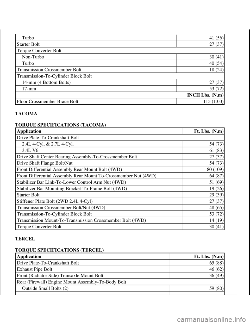
TACOMA
TORQUE SPECIFICATIONS (TACOMA)
TERCEL
TORQUE SPECIFICATIONS (TERCEL)
Turbo41 (56)
Starter Bolt27 (37)
Torque Converter Bolt
Non-Turbo30 (41)
Turbo40 (54)
Transmission Crossmember Bolt18 (24)
Transmission-To-Cylinder Block Bolt
14-mm (4 Bottom Bolts)27 (37)
17-mm53 (72)
INCH Lbs. (N.m)
Floor Crossmember Brace Bolt115 (13.0)
ApplicationFt. Lbs. (N.m)
Drive Plate-To-Crankshaft Bolt
2.4L 4-Cyl. & 2.7L 4-Cyl.54 (73)
3.4L V661 (83)
Drive Shaft Center Bearing Assembly-To-Crossmember Bolt27 (37)
Drive Shaft Flange Bolt/Nut54 (73)
Front Differential Assembly Rear Mount Bolt (4WD)80 (109)
Front Differential Assembly Rear Mount To-Crossmember Nut (4WD)64 (87)
Stabilizer Bar Link-To-Lower Control Arm Nut (4WD)51 (69)
Stabilizer Bar Mounting Bracket-To-Frame Bolt (4WD)19 (26)
Starter Bolt29 (39)
Stiffener Plate Bolt (2WD 2.4L 4-Cyl)27 (37)
Transmission Crossmember Bolt/Nut (4WD)48 (65)
Transmission-To-Cylinder Block Bolt53 (72)
Transmission Mount-To-Transmission Crossmember Bolt (4WD)14 (19)
Torque Converter Bolt30 (41)
ApplicationFt. Lbs. (N.m)
Drive Plate-To-Crankshaft Bolt65 (88)
Exhaust Pipe Bolt46 (62)
Front (Radiator Side) Transaxle Mount Bolt36 (49)
Rear (Firewall) Engine Mount Assembly-To-Body Bolt
Outside Small Bolts (2)59 (80)
1998 Toyota Avalon XLS
TRANSMISSION SERVICING - A/T 1997-98 TRANSMISSION SERVICING Toyota - Transmission Removal &
Installation
Helpmelearn
November-03-08 10:30:29 AMPage 40 © 2005 Mitchell Repair Information Company, LLC.
Page 156 of 1632
DESCRIPTION
The A-540H 4WD transaxle has a center differential and electronic transfer case attached. Transaxle internal
components are the same or similar to the A-540E and A-541E transaxles. Transaxle has 4 shift solenoids in the
valve body to control engagement speed and throttle pressure for shift feel. Torque is distributed to front and
rear wheels at all times to maximize traction of 4WD vehicle.
The A-540E and A-541E transaxles feature a torque converter with lock-up clutch, 4-speed planetary gear unit,
differential, hydraulic control system, shift solenoids and electronic control system. The A-541E transaxle has
an additional shift solenoid in the valve body to control engagement speed and throttle pressure for shift feel. A
shift lock mechanism is used to minimize possibility of incorrect operation of transaxle.
LUBRICATION
On all models except RAV4 4WD, transaxle uses D-II or DEXRON-III transmission fluid. On RAV4 4WD,
transaxle uses type "T" or type "T"-IV transmission fluid. For transaxle refill capacities, see TRANSAXLE
CAPACITIES table.
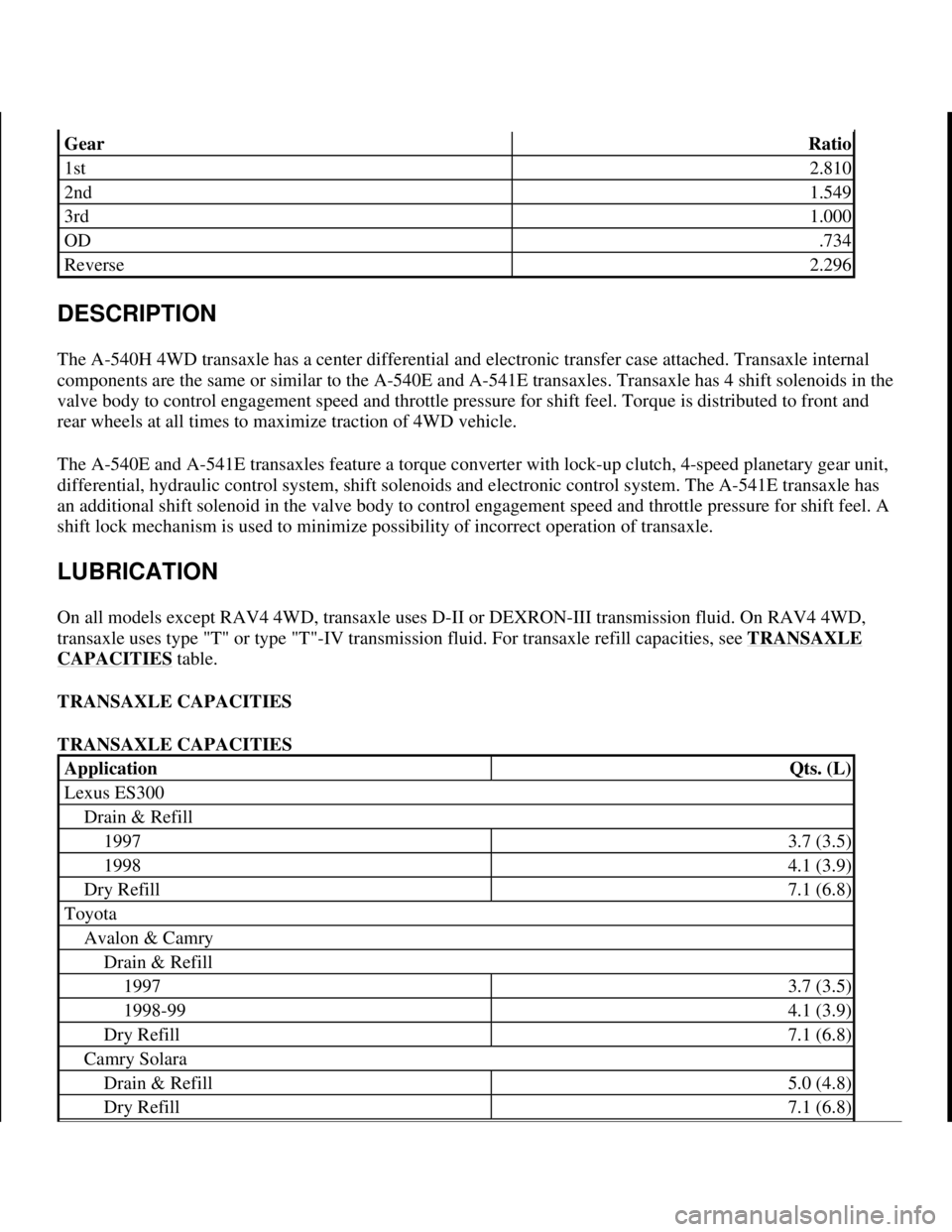
TRANSAXLE CAPACITIES
TRANSAXLE CAPACITIES
GearRatio
1st2.810
2nd1.549
3rd1.000
OD.734
Reverse2.296
ApplicationQts. (L)
Lexus ES300
Drain & Refill
19973.7 (3.5)
19984.1 (3.9)
Dry Refill7.1 (6.8)
Toyota
Avalon & Camry
Drain & Refill
19973.7 (3.5)
1998-994.1 (3.9)
Dry Refill7.1 (6.8)
Camry Solara
Drain & Refill5.0 (4.8)
Dry Refill7.1 (6.8)
1998 Toyota Avalon XLS
1997-99 AUTOMATIC TRANSMISSIONS Toyota A-540E, A-540H & A-541E Overhaul
Helpmelearn
November-03-08 10:28:16 AMPage 2 © 2005 Mitchell Repair Information Company, LLC.
Page 164 of 1632
1. If shift lever is actuated with engine idling, a time lag will be noted before shock can be felt. This test is
used for checking condition of OD direct clutch, forward clutch, direct clutch, and 1st and reverse brake.
2. Apply parking brake. Start engine. On RAV4, ensure idle speed is 700-800 RPM. On all other models,
ensure idle speed is 650-750 RPM. Shift transaxle from "N" into "D" range. Use a stop watch to measure
elapsed time between shifting of lever until shock is felt. Standard time lag is less than 1.2 seconds.
3. Repeat procedure outlined in step 2) to measure time lag for "N" to "R". Standard lag time is less than 1.5
seconds.
4. If "N" to "D" time lag is longer than specification, line pressure is too low, forward clutch may be worn,
or OD one-way clutch is not operating properly.
5. If "N" to "R" time lag is longer than specified, direct clutch may be worn, 1st and reverse brake may be
worn, line pressure is too low or OD one-way clutch is not operating properly.
ROAD TEST
"D" Range Test In NORM & PWR Pattern Ranges
1. Shift into "D" range. Hold accelerator pedal constant at full throttle. Place shift mode button in NORM or
PWR position. Check 1-2, 2-3, and 3-OD lock-up and upshift points. See appropriate table under SHIFT
SPEED SPECIFICATIONS .
zIf no 1-2 upshift occurs, check 1-2 shift valve or solenoid.
zIf no 2-3 upshift occurs, check 2-3 shift valve or solenoid.
zIf no 3-OD upshift occurs, check 3-OD shift valve.
zIf all shift points are incorrect, check throttle valve, 1-2 shift valve, 2-3 shift valve and 3-OD shift
valve.
zIf all lock-up points are incorrect, check lock-up relay valve or shift solenoid valve SL.
2. Use procedure outlined in step 1) to check for shock and slip between 1-2, 2-3, and 3-OD upshifts. If
shock is harsh, line pressure may be too high. Check accumulator or check ball.
3. Run vehicle in "D" range lock-up or overdrive gear. Check for abnormal noise and vibration.
4. While running in "D" range, confirm correct kickdown vehicle speed limits for 2-1, 3-2, OD-3 shift
points. Check for abnormal shock and slip at kickdown.
5. Check loc
k-up function. Drive vehicle in OD gear of "D" range with lock-up on. Hold vehicle speed NOTE: Perform test at normal operating fluid temperature of 122-176°F (50-80°C).
NOTE: There is no overdrive upshift when coolant temperature is below 140°F
(60°C). There is no lock-up when vehicle speed is 6 MPH less than the set
cruise control speed.
NOTE: Check for cause of abnormal noise and vibration must be made with
extreme care as problem could be due to an unbalanced drive shaft,
differential, tire, torque converter, etc.
1998 Toyota Avalon XLS
1997-99 AUTOMATIC TRANSMISSIONS Toyota A-540E, A-540H & A-541E Overhaul
Helpmelearn
November-03-08 10:28:17 AMPage 10 © 2005 Mitchell Repair Information Company, LLC.
Page 176 of 1632
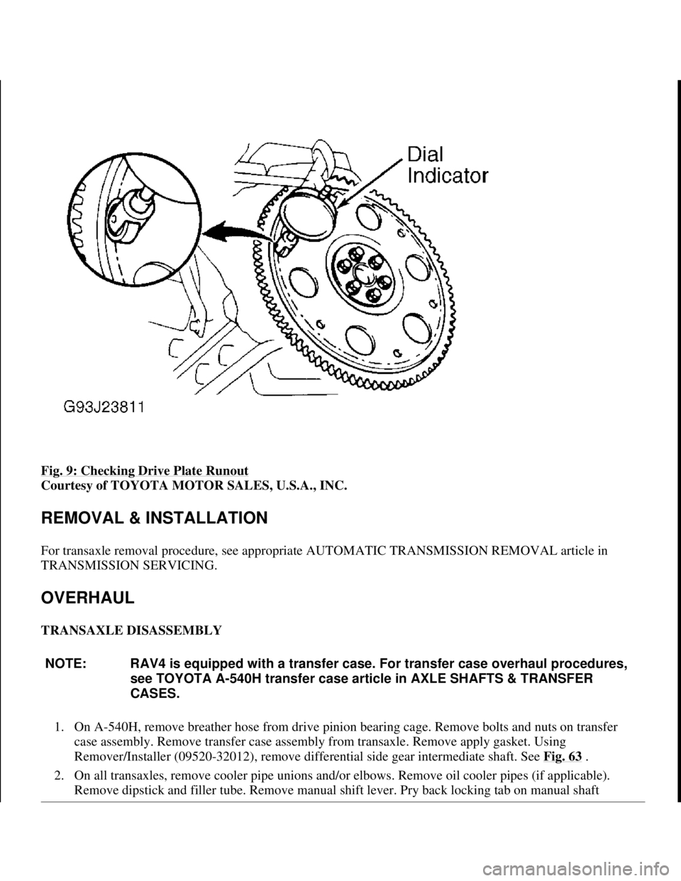
Fig. 9: Checking Drive Plate Runout
Courtesy of TOYOTA MOTOR SALES, U.S.A., INC.
REMOVAL & INSTALLATION
For transaxle removal procedure, see appropriate AUTOMATIC TRANSMISSION REMOVAL article in
TRANSMISSION SERVICING.
OVERHAUL
TRANSAXLE DISASSEMBLY
1. On A-540H, remove breather hose from drive pinion bearing cage. Remove bolts and nuts on transfer
case assembly. Remove transfer case assembly from transaxle. Remove apply gasket. Using
Remover/Installer (09520-32012), remove differential side gear intermediate shaft. See Fig. 63
.
2. On all transaxles, remove cooler pipe unions and/or elbows. Remove oil cooler pipes (if applicable).
Remove dipstick and filler tube. Remove manual shift lever. Pry back locking tab on manual shaft
NOTE: RAV4 is equipped with a transfer case. For transfer case overhaul procedures,
see TOYOTA A-540H transfer case article in AXLE SHAFTS & TRANSFER
CASES.
1998 Toyota Avalon XLS
1997-99 AUTOMATIC TRANSMISSIONS Toyota A-540E, A-540H & A-541E Overhaul
Helpmelearn
November-03-08 10:28:17 AMPage 22 © 2005 Mitchell Repair Information Company, LLC.
Page 177 of 1632
washer. Remove nut and washer. Remove Park/Neutral Position (PNP) switch.
3. Remove throttle cable retaining bolt. Remove solenoid harness connector retaining bolt (if applicable).
Remove vehicle speed sensor mounted in differential cover. Remove sensor adapter. Remove direct
clutch speed (T/M revolution) sensor mounted to upper case cover (if equipped). Remove upper case
cover. Remove transaxle oil pan. Examine any contamination in pan to aid in diagnosis.
4. Remove oil stainer (filter) and oil pipe hold-down bracket. Remove manual valve body including detent
spring. Gently remove all oil pipes by prying up on end of pipe with screwdriver.
5. Disconnect solenoid harness connectors. Remove connector clamp and apply pipe retainer. Remove 1st
and reverse apply pipe. Remove valve body bolts. Remove wiring harness clamp. Disconnect throttle
cable from cam and remove valve body.
6. Remove throttle cable and solenoid wiring harness. Remove 2nd brake apply gasket. Loosen accumulator
cover bolts in crisscross pattern. Remove cover and gasket. Remove forward clutch accumulator. See Fi
g.
10 .
7. Remove remaining accumulators by applying 14 psi (1kg/cm
2 ) of air pressure to apply hole. See Fig.
11 . Cover accumulator bores with a rag when applying air.
8. Mark 2nd coast brake servo apply piston rod where it meets case. Apply 57-114 psi (4-8 kg/cm
2 ) of air
pressure to apply hole and measure piston rod travel (stroke). See Fig. 12
. Piston rod travel should
be .079-.138" (2.0-3.5 mm). If rod travel is not within specification, further inspect band during
disassembly.
9. Remove 2nd coast brake piston cover snap ring. Apply air to oil hole and remove cover and piston
assembly. See Fig. 12
. Remove oil pump bolts. Using appropriate puller, remove oil pump.
10. Remove direct clutch and forward clutch. Separate components and remove thrust washer. Remove thrust
bearings from front and rear of forward clutch. Push out 2nd coast brake band anchor pin. Remove band
and inspect.
11. Remove front planetary ring gear. Remove front planetary gear with thrust bearings on either side.
Remove thrust bearings. Remove sun gear shell with thrust washer.
12. Apply compressed air to 2nd brake piston port and check operation of 2nd brake. See Fig. 13
. Remove
2nd coast brake band guide. DO NOT separate band guide and bolt. Remove snap ring securing 2nd
brake drum. Remove drum.
13. Remove 2nd brake piston return spring. Remove No. 1 one-way clutch. Remove 2nd brake clutch discs,
plates and flange. Note number and location of components. Remove snap ring securing No. 2 one-way
clutch and rear planetary gear. See Fig. 14
. Remove components.
14. Remove thrust washer from rear planetary gear. Remove rear planetary ring gear with thrust bearing.
Apply air into appropriate passage to check 1st and reverse brake operation. See Fig. 15
.
15. Using feeler gauge, check pack clearance of 1st and reverse brake assembly. Clearance should be .033-
.081" (.85-2.05 mm) for A-540E transaxle, .041-.085" (1.04-2.16 mm) for A-540H transaxle, or .076-
.106" (1.92-2.68 mm) for A-541E transaxle. Remove snap ring securing 1st and reverse brake. Remove
1st and reverse brake discs, plates and flange. Note number and location of components.
16. From back of transaxle, remove 13 bolts securing overdrive unit. Using soft-faced hammer, tap around
outside of case until overdrive unit loosens and can be removed.
17. Remove overdrive (OD) planetary gear from transaxle case. Remove OD brake drum. See Fig. 14
.
Remove gaskets for OD clutch apply and OD brake apply ports.
18. Usin
g appropriate compressor, compress 1st and reverse piston. See Fig. 16 . Remove snap ring. Apply
1998 Toyota Avalon XLS
1997-99 AUTOMATIC TRANSMISSIONS Toyota A-540E, A-540H & A-541E Overhaul
Helpmelearn
November-03-08 10:28:17 AMPage 23 © 2005 Mitchell Repair Information Company, LLC.
Page 183 of 1632
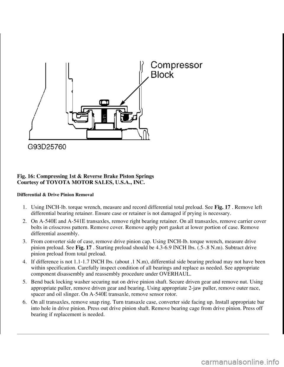
Fig. 16: Compressing 1st & Reverse Brake Piston Springs
Courtesy of TOYOTA MOTOR SALES, U.S.A., INC.
Differential & Drive Pinion Removal
1. Using INCH-lb. torque wrench, measure and record differential total preload. See Fig. 17 . Remove left
differential bearing retainer. Ensure case or retainer is not damaged if prying is necessary.
2. On A-540E and A-541E transaxles, remove right bearing retainer. On all transaxles, remove carrier cover
bolts in crisscross pattern. Remove cover. Remove apply port gasket at lower portion of case. Remove
differential assembly.
3. From converter side of case, remove drive pinion cap. Using INCH-lb. torque wrench, measure drive
pinion preload. See Fig. 17
. Starting preload should be 4.3-6.9 INCH lbs. (.5-.8 N.m). Subtract drive
pinion preload from total preload.
4. If difference is not 1.1-1.7 INCH lbs. (about .1 N.m), differential side bearing preload may not have been
within specification. Carefully inspect condition of all bearings and replace as needed. See appropriate
component disassembly and reassembly procedure under OVERHAUL.
5. Bend back locking washer securing nut on drive pinion shaft. Secure driven gear and remove nut. Using
appropriate puller, remove driven gear and bearing. Using appropriate 2-jaw puller, remove outer race,
spacer and oil slinger. On A-540E transaxle, remove sensor rotor.
6. On all transaxles, remove snap ring. Turn transaxle case, converter side facing up. Install appropriate bar
into hole in drive pinion. Press out drive pinion shaft. Remove bearing cage from drive pinion. Press off
bearing if replacement is needed.
1998 Toyota Avalon XLS
1997-99 AUTOMATIC TRANSMISSIONS Toyota A-540E, A-540H & A-541E Overhaul
Helpmelearn
November-03-08 10:28:17 AMPage 29 © 2005 Mitchell Repair Information Company, LLC.
Page 227 of 1632
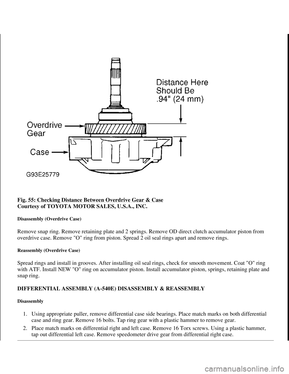
Fig. 55: Checking Distance Between Overdrive Gear & Case
Courtesy of TOYOTA MOTOR SALES, U.S.A., INC.
Disassembly (Overdrive Case)
Remove snap ring. Remove retaining plate and 2 springs. Remove OD direct clutch accumulator piston from
overdrive case. Remove "O" ring from piston. Spread 2 oil seal rings apart and remove rings.
Reassembly (Overdrive Case)
Spread rings and install in grooves. After installing oil seal rings, check for smooth movement. Coat "O" ring
with ATF. Install NEW "O" ring on accumulator piston. Install accumulator piston, springs, retaining plate and
snap ring.
DIFFERENTIAL ASSEMBLY (A-540E) DISASSEMBLY & REASSEMBLY
Disassembly
1. Using appropriate puller, remove differential case side bearings. Place match marks on both differential
case and ring gear. Remove 16 bolts. Tap ring gear with a plastic hammer to remove gear.
2. Place match marks on differential right and left case. Remove 16 Torx screws. Using a plastic hammer,
tap out differential left case. Remove speedometer drive
gear from differential right case.
1998 Toyota Avalon XLS
1997-99 AUTOMATIC TRANSMISSIONS Toyota A-540E, A-540H & A-541E Overhaul
Helpmelearn
November-03-08 10:28:19 AMPage 73 © 2005 Mitchell Repair Information Company, LLC.
Page 228 of 1632
3. Remove differential side gears, side thrust washers, differential spider, differential pinions and pinion
washers from differential left case. See Fig. 56
.
4. Using a hammer and screwdriver, remove oil seal. Remove oil baffle from left bearing retainer. Drive out
outer race and adjusting shim from left bearing retainer with a hammer and brass drift. Remove right oil
seal from retainer.
Reassembly
1. Install right oil seal to retainer. Drive in NEW oil seal until seal surface is flush with surface of retainer.
Coat oil seal lip with grease.
2. Install original adjusting shim and bearing outer race to left bearing retainer. Shim should
be .0945" (2.400 mm). Press outer race into left retainer. Install oil baffle and oil seal after adjusting
differential side bearing preload. See TRANSAXLE REASSEMBLY
.
3. Assemble differential case. Coat all sliding and rotating surfaces with ATF before assembly. Install thrust
washer to side gear. Install pinions and thrust washers to spider. Install side gear and spider with pinions
to differential left case. Using a dial indicator, measure side gear backlash while holding one pinion
against carrier casing. See Fig. 60
. Backlash should be .002-.008" (.05-.20 mm). Install side gear and
spider with pinions to right side of differential case. Check pinion gear backlash.
4. Select side gear thrust washer which ensures backlash is within specification. Side gear thrust washers are
available in thicknesses from .0315" (.80 mm) to .0551" (1.40 mm) in .004" (.10 mm) increments. Select
washers of the same size for both sides. Install speedometer driven gear.
5. Align match marks on differential cases. Using plastic hammer, carefully tap differential right case. Using
a Torx wrench, install and tighten 16 Torx screws to 46 ft. lbs. (63 N.m).
6. Clean differential case contact surface with cleaning solvent. Heat ring gear to about 212°F (100°C) in an
oil bath. DO NOT heat ring above 230°F (110°C). Clean contact surface of ring gear with cleaning
solvent. Quickly install ring gear on differential case. Tighten bolts to 91 ft. lbs. (124 N.m). Install right
and left side bearin
g to differential case.
1998 Toyota Avalon XLS
1997-99 AUTOMATIC TRANSMISSIONS Toyota A-540E, A-540H & A-541E Overhaul
Helpmelearn
November-03-08 10:28:19 AMPage 74 © 2005 Mitchell Repair Information Company, LLC.