rear suspension TOYOTA RAV4 1996 Service Repair Manual
[x] Cancel search | Manufacturer: TOYOTA, Model Year: 1996, Model line: RAV4, Model: TOYOTA RAV4 1996Pages: 1632, PDF Size: 41.64 MB
Page 29 of 1632
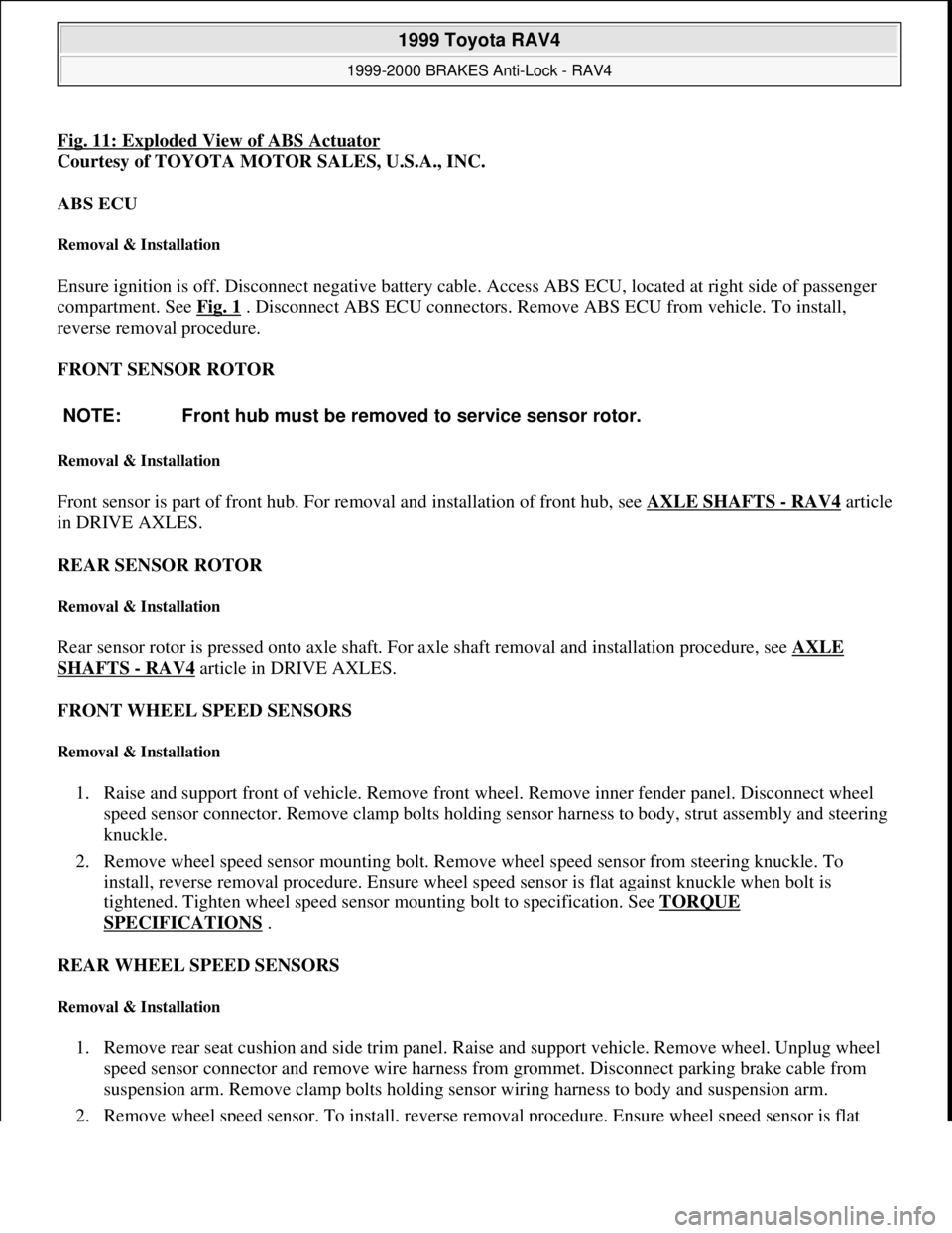
Fig. 11: Exploded View of ABS Actuator
Courtesy of TOYOTA MOTOR SALES, U.S.A., INC.
ABS ECU
Removal & Installation
Ensure ignition is off. Disconnect negative battery cable. Access ABS ECU, located at right side of passenger
compartment. See Fig. 1
. Disconnect ABS ECU connectors. Remove ABS ECU from vehicle. To install,
reverse removal procedure.
FRONT SENSOR ROTOR
Removal & Installation
Front sensor is part of front hub. For removal and installation of front hub, see AXLE SHAFTS - RAV4 article
in DRIVE AXLES.
REAR SENSOR ROTOR
Removal & Installation
Rear sensor rotor is pressed onto axle shaft. For axle shaft removal and installation procedure, see AXLE
SHAFTS - RAV4 article in DRIVE AXLES.
FRONT WHEEL SPEED SENSORS
Removal & Installation
1. Raise and support front of vehicle. Remove front wheel. Remove inner fender panel. Disconnect wheel
speed sensor connector. Remove clamp bolts holding sensor harness to body, strut assembly and steering
knuckle.
2. Remove wheel speed sensor mounting bolt. Remove wheel speed sensor from steering knuckle. To
install, reverse removal procedure. Ensure wheel speed sensor is flat against knuckle when bolt is
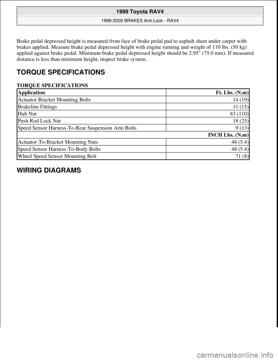
tightened. Tighten wheel speed sensor mounting bolt to specification. See TORQUE
SPECIFICATIONS .
REAR WHEEL SPEED SENSORS
Removal & Installation
1. Remove rear seat cushion and side trim panel. Raise and support vehicle. Remove wheel. Unplug wheel
speed sensor connector and remove wire harness from grommet. Disconnect parking brake cable from
suspension arm. Remove clamp bolts holding sensor wiring harness to body and suspension arm.
2. Remove wheel speed sensor. To install, reverse removal procedure. Ensure wheel speed sensor is flat NOTE: Front hub must be removed to service sensor rotor.
1999 Toyota RAV4
1999-2000 BRAKES Anti-Lock - RAV4
Microsoft
Sunday, November 22, 2009 10:06:17 AMPage 29 © 2005 Mitchell Repair Information Company, LLC.
Page 32 of 1632
Brake pedal depressed height is measured from face of brake pedal pad to asphalt sheet under carpet with
brakes applied. Measure brake pedal depressed height with engine running and weight of 110 lbs. (50 kg)
applied against brake pedal. Minimum brake pedal depressed height should be 2.95" (75.0 mm). If measured
distance is less than minimum height, inspect brake system.
TORQUE SPECIFICATIONS
TORQUE SPECIFICATIONS
WIRING DIAGRAMS
ApplicationFt. Lbs. (N.m)
Actuator Bracket Mounting Bolts14 (19)
Brakeline Fittings11 (15)
Hub Nut83 (110)
Push Rod Lock Nut18 (25)
Speed Sensor Harness-To-Rear Suspension Arm Bolts9 (13)
INCH Lbs. (N.m)
Actuator-To-Bracket Mounting Nuts48 (5.4)
Speed Sensor Harness-To-Body Bolts48 (5.4)
Wheel Speed Sensor Mounting Bolt71 (8)
1999 Toyota RAV4
1999-2000 BRAKES Anti-Lock - RAV4
Microsoft
Sunday, November 22, 2009 10:06:17 AMPage 32 © 2005 Mitchell Repair Information Company, LLC.
Page 118 of 1632
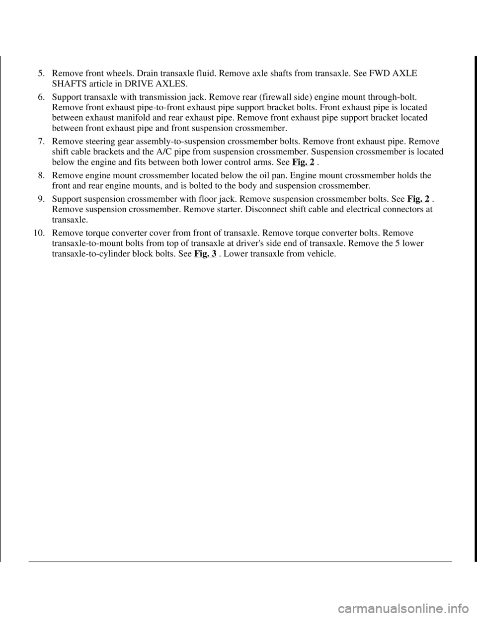
5. Remove front wheels. Drain transaxle fluid. Remove axle shafts from transaxle. See FWD AXLE
SHAFTS article in DRIVE AXLES.
6. Support transaxle with transmission jack. Remove rear (firewall side) engine mount through-bolt.
Remove front exhaust pipe-to-front exhaust pipe support bracket bolts. Front exhaust pipe is located
between exhaust manifold and rear exhaust pipe. Remove front exhaust pipe support bracket located
between front exhaust pipe and front suspension crossmember.
7. Remove steering gear assembly-to-suspension crossmember bolts. Remove front exhaust pipe. Remove
shift cable brackets and the A/C pipe from suspension crossmember. Suspension crossmember is located
below the engine and fits between both lower control arms. See Fig. 2
.
8. Remove engine mount crossmember located below the oil pan. Engine mount crossmember holds the
front and rear engine mounts, and is bolted to the body and suspension crossmember.
9. Support suspension crossmember with floor jack. Remove suspension crossmember bolts. See Fig. 2
.
Remove suspension crossmember. Remove starter. Disconnect shift cable and electrical connectors at
transaxle.
10. Remove torque converter cover from front of transaxle. Remove torque converter bolts. Remove
transaxle-to-mount bolts from top of transaxle at driver's side end of transaxle. Remove the 5 lower
transaxle-to-c
ylinder block bolts. See Fig. 3. Lower transaxle from vehicle.
1998 Toyota Avalon XLS
TRANSMISSION SERVICING - A/T 1997-98 TRANSMISSION SERVICING Toyota - Transmission Removal &
Installation
Helpmelearn
November-03-08 10:30:28 AMPage 6 © 2005 Mitchell Repair Information Company, LLC.
Page 121 of 1632
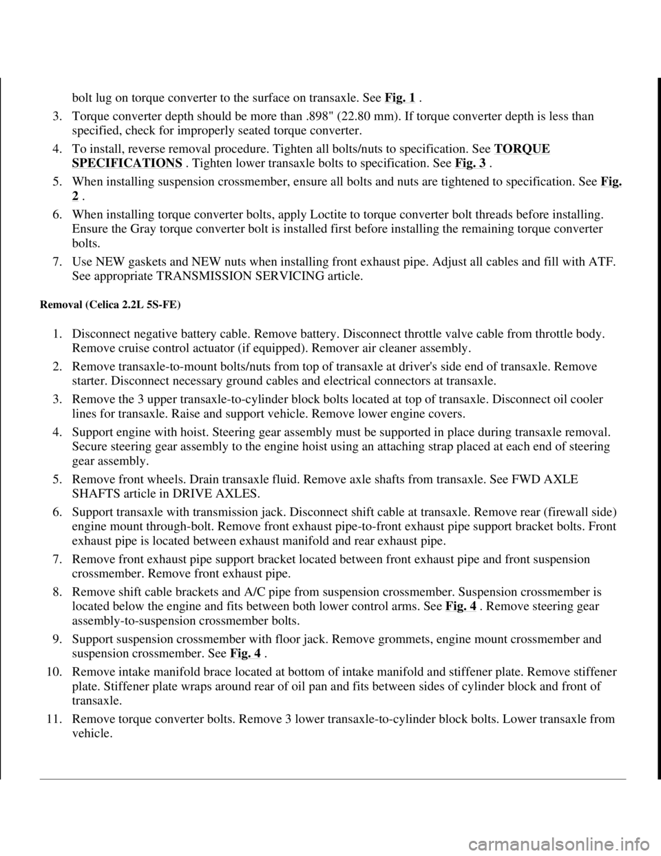
bolt lug on torque converter to the surface on transaxle. See Fig. 1.
3. Torque converter depth should be more than .898" (22.80 mm). If torque converter depth is less than
specified, check for improperly seated torque converter.
4. To install, reverse removal procedure. Tighten all bolts/nuts to specification. See TORQUE
SPECIFICATIONS . Tighten lower transaxle bolts to specification. See Fig. 3 .
5. When installing suspension crossmember, ensure all bolts and nuts are tightened to specification. See Fi
g.
2 .
6. When installing torque converter bolts, apply Loctite to torque converter bolt threads before installing.
Ensure the Gray torque converter bolt is installed first before installing the remaining torque converter
bolts.
7. Use NEW gaskets and NEW nuts when installing front exhaust pipe. Adjust all cables and fill with ATF.
See appropriate TRANSMISSION SERVICING article.
Removal (Celica 2.2L 5S-FE)
1. Disconnect negative battery cable. Remove battery. Disconnect throttle valve cable from throttle body.
Remove cruise control actuator (if equipped). Remover air cleaner assembly.
2. Remove transaxle-to-mount bolts/nuts from top of transaxle at driver's side end of transaxle. Remove
starter. Disconnect necessary ground cables and electrical connectors at transaxle.
3. Remove the 3 upper transaxle-to-cylinder block bolts located at top of transaxle. Disconnect oil cooler
lines for transaxle. Raise and support vehicle. Remove lower engine covers.
4. Support engine with hoist. Steering gear assembly must be supported in place during transaxle removal.
Secure steering gear assembly to the engine hoist using an attaching strap placed at each end of steering
gear assembly.
5. Remove front wheels. Drain transaxle fluid. Remove axle shafts from transaxle. See FWD AXLE
SHAFTS article in DRIVE AXLES.
6. Support transaxle with transmission jack. Disconnect shift cable at transaxle. Remove rear (firewall side)
engine mount through-bolt. Remove front exhaust pipe-to-front exhaust pipe support bracket bolts. Front
exhaust pipe is located between exhaust manifold and rear exhaust pipe.
7. Remove front exhaust pipe support bracket located between front exhaust pipe and front suspension
crossmember. Remove front exhaust pipe.
8. Remove shift cable brackets and A/C pipe from suspension crossmember. Suspension crossmember is
located below the engine and fits between both lower control arms. See Fig. 4
. Remove steering gear
assembly-to-suspension crossmember bolts.
9. Support suspension crossmember with floor jack. Remove grommets, engine mount crossmember and
suspension crossmember. See Fig. 4
.
10. Remove intake manifold brace located at bottom of intake manifold and stiffener plate. Remove stiffener
plate. Stiffener plate wraps around rear of oil pan and fits between sides of cylinder block and front of
transaxle.
11. Remove torque converter bolts. Remove 3 lower transaxle-to-cylinder block bolts. Lower transaxle from
vehicle.
1998 Toyota Avalon XLS
TRANSMISSION SERVICING - A/T 1997-98 TRANSMISSION SERVICING Toyota - Transmission Removal &
Installation
Helpmelearn
November-03-08 10:30:28 AMPage 9 © 2005 Mitchell Repair Information Company, LLC.
Page 123 of 1632
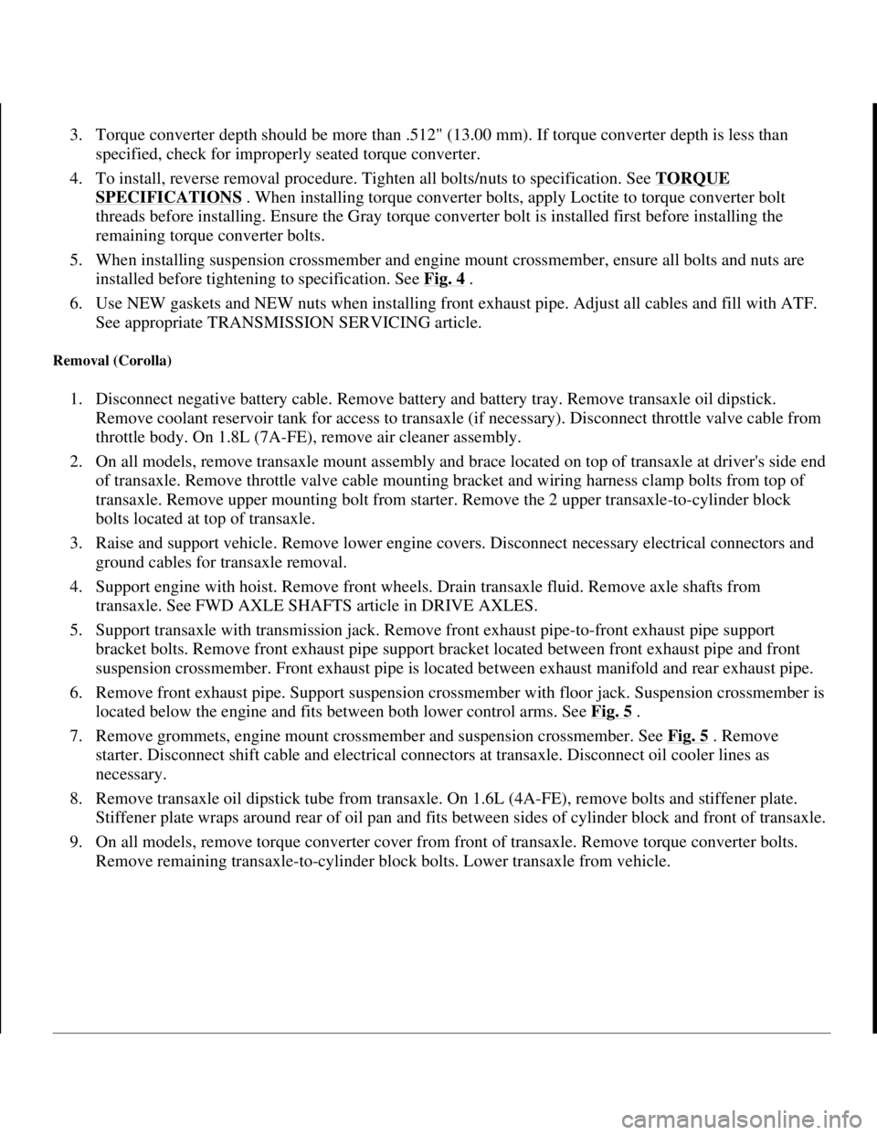
3. Torque converter depth should be more than .512" (13.00 mm). If torque converter depth is less than
specified, check for improperly seated torque converter.
4. To install, reverse removal procedure. Tighten all bolts/nuts to specification. See TORQUE
SPECIFICATIONS . When installing torque converter bolts, apply Loctite to torque converter bolt
threads before installing. Ensure the Gray torque converter bolt is installed first before installing the
remaining torque converter bolts.
5. When installing suspension crossmember and engine mount crossmember, ensure all bolts and nuts are
installed before tightening to specification. See Fig. 4
.
6. Use NEW gaskets and NEW nuts when installing front exhaust pipe. Adjust all cables and fill with ATF.
See appropriate TRANSMISSION SERVICING article.
Removal (Corolla)
1. Disconnect negative battery cable. Remove battery and battery tray. Remove transaxle oil dipstick.
Remove coolant reservoir tank for access to transaxle (if necessary). Disconnect throttle valve cable from
throttle body. On 1.8L (7A-FE), remove air cleaner assembly.
2. On all models, remove transaxle mount assembly and brace located on top of transaxle at driver's side end
of transaxle. Remove throttle valve cable mounting bracket and wiring harness clamp bolts from top of
transaxle. Remove upper mounting bolt from starter. Remove the 2 upper transaxle-to-cylinder block
bolts located at top of transaxle.
3. Raise and support vehicle. Remove lower engine covers. Disconnect necessary electrical connectors and
ground cables for transaxle removal.
4. Support engine with hoist. Remove front wheels. Drain transaxle fluid. Remove axle shafts from
transaxle. See FWD AXLE SHAFTS article in DRIVE AXLES.
5. Support transaxle with transmission jack. Remove front exhaust pipe-to-front exhaust pipe support
bracket bolts. Remove front exhaust pipe support bracket located between front exhaust pipe and front
suspension crossmember. Front exhaust pipe is located between exhaust manifold and rear exhaust pipe.
6. Remove front exhaust pipe. Support suspension crossmember with floor jack. Suspension crossmember is
located below the engine and fits between both lower control arms. See Fig. 5
.
7. Remove grommets, engine mount crossmember and suspension crossmember. See Fig. 5
. Remove
starter. Disconnect shift cable and electrical connectors at transaxle. Disconnect oil cooler lines as
necessary.
8. Remove transaxle oil dipstick tube from transaxle. On 1.6L (4A-FE), remove bolts and stiffener plate.
Stiffener plate wraps around rear of oil pan and fits between sides of cylinder block and front of transaxle.
9. On all models, remove torque converter cover from front of transaxle. Remove torque converter bolts.
Remove remainin
g transaxle-to-cylinder block bolts. Lower transaxle from vehicle.
1998 Toyota Avalon XLS
TRANSMISSION SERVICING - A/T 1997-98 TRANSMISSION SERVICING Toyota - Transmission Removal &
Installation
Helpmelearn
November-03-08 10:30:28 AMPage 11 © 2005 Mitchell Repair Information Company, LLC.
Page 131 of 1632
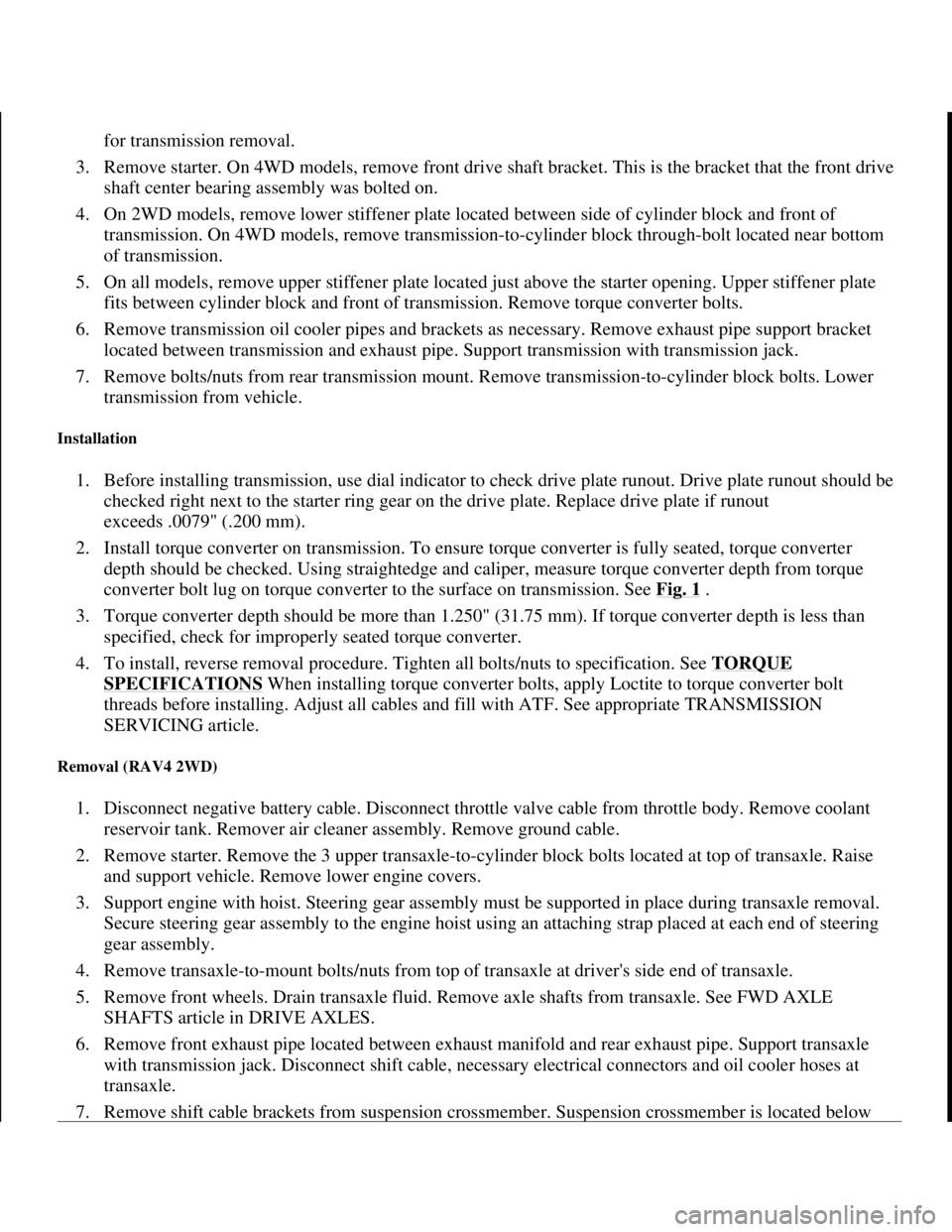
for transmission removal.
3. Remove starter. On 4WD models, remove front drive shaft bracket. This is the bracket that the front drive
shaft center bearing assembly was bolted on.
4. On 2WD models, remove lower stiffener plate located between side of cylinder block and front of
transmission. On 4WD models, remove transmission-to-cylinder block through-bolt located near bottom
of transmission.
5. On all models, remove upper stiffener plate located just above the starter opening. Upper stiffener plate
fits between cylinder block and front of transmission. Remove torque converter bolts.
6. Remove transmission oil cooler pipes and brackets as necessary. Remove exhaust pipe support bracket
located between transmission and exhaust pipe. Support transmission with transmission jack.
7. Remove bolts/nuts from rear transmission mount. Remove transmission-to-cylinder block bolts. Lower
transmission from vehicle.
Installation
1. Before installing transmission, use dial indicator to check drive plate runout. Drive plate runout should be
checked right next to the starter ring gear on the drive plate. Replace drive plate if runout
exceeds .0079" (.200 mm).
2. Install torque converter on transmission. To ensure torque converter is fully seated, torque converter
depth should be checked. Using straightedge and caliper, measure torque converter depth from torque
converter bolt lug on torque converter to the surface on transmission. See Fig. 1
.
3. Torque converter depth should be more than 1.250" (31.75 mm). If torque converter depth is less than
specified, check for improperly seated torque converter.
4. To install, reverse removal procedure. Tighten all bolts/nuts to specification. See TORQUE
SPECIFICATIONS When installing torque converter bolts, apply Loctite to torque converter bolt
threads before installing. Adjust all cables and fill with ATF. See appropriate TRANSMISSION
SERVICING article.
Removal (RAV4 2WD)
1. Disconnect negative battery cable. Disconnect throttle valve cable from throttle body. Remove coolant
reservoir tank. Remover air cleaner assembly. Remove ground cable.
2. Remove starter. Remove the 3 upper transaxle-to-cylinder block bolts located at top of transaxle. Raise
and support vehicle. Remove lower engine covers.
3. Support engine with hoist. Steering gear assembly must be supported in place during transaxle removal.
Secure steering gear assembly to the engine hoist using an attaching strap placed at each end of steering
gear assembly.
4. Remove transaxle-to-mount bolts/nuts from top of transaxle at driver's side end of transaxle.
5. Remove front wheels. Drain transaxle fluid. Remove axle shafts from transaxle. See FWD AXLE
SHAFTS article in DRIVE AXLES.
6. Remove front exhaust pipe located between exhaust manifold and rear exhaust pipe. Support transaxle
with transmission jack. Disconnect shift cable, necessary electrical connectors and oil cooler hoses at
transaxle.
7. Remove shift cable brackets from suspension crossmember. Suspension crossmember is located below
1998 Toyota Avalon XLS
TRANSMISSION SERVICING - A/T 1997-98 TRANSMISSION SERVICING Toyota - Transmission Removal &
Installation
Helpmelearn
November-03-08 10:30:28 AMPage 19 © 2005 Mitchell Repair Information Company, LLC.
Page 146 of 1632
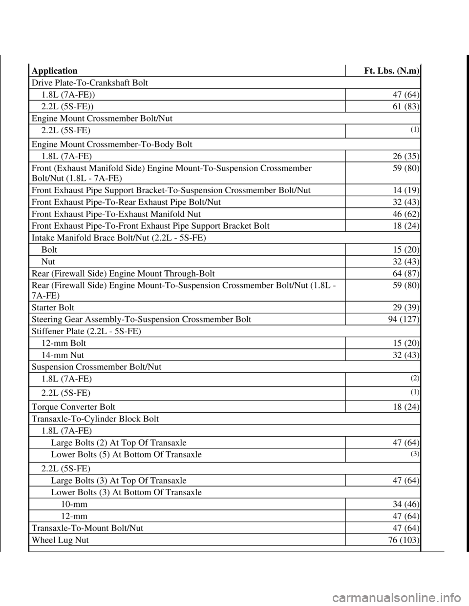
ApplicationFt. Lbs. (N.m)
Drive Plate-To-Crankshaft Bolt
1.8L (7A-FE))47 (64)
2.2L (5S-FE))61 (83)
Engine Mount Crossmember Bolt/Nut
2.2L (5S-FE)(1)
Engine Mount Crossmember-To-Body Bolt
1.8L (7A-FE)26 (35)
Front (Exhaust Manifold Side) Engine Mount-To-Suspension Crossmember
Bolt/Nut (1.8L - 7A-FE)59 (80)
Front Exhaust Pipe Support Bracket-To-Suspension Crossmember Bolt/Nut14 (19)
Front Exhaust Pipe-To-Rear Exhaust Pipe Bolt/Nut32 (43)
Front Exhaust Pipe-To-Exhaust Manifold Nut46 (62)
Front Exhaust Pipe-To-Front Exhaust Pipe Support Bracket Bolt18 (24)
Intake Manifold Brace Bolt/Nut (2.2L - 5S-FE)
Bolt15 (20)
Nut32 (43)
Rear (Firewall Side) Engine Mount Through-Bolt64 (87)
Rear (Firewall Side) Engine Mount-To-Suspension Crossmember Bolt/Nut (1.8L -
7A-FE)59 (80)
Starter Bolt29 (39)
Steering Gear Assembly-To-Suspension Crossmember Bolt94 (127)
Stiffener Plate (2.2L - 5S-FE)
12-mm Bolt15 (20)
14-mm Nut32 (43)
Suspension Crossmember Bolt/Nut
1.8L (7A-FE)(2)
2.2L (5S-FE)(1)
Torque Converter Bolt18 (24)
Transaxle-To-Cylinder Block Bolt
1.8L (7A-FE)
Large Bolts (2) At Top Of Transaxle47 (64)
Lower Bolts (5) At Bottom Of Transaxle(3)
2.2L (5S-FE)
Large Bolts (3) At Top Of Transaxle47 (64)
Lower Bolts (3) At Bottom Of Transaxle
10-mm34 (46)
12-mm47 (64)
Transaxle-To-Mount Bolt/Nut47 (64)
Wheel Lug Nut76 (103)
1998 Toyota Avalon XLS
TRANSMISSION SERVICING - A/T 1997-98 TRANSMISSION SERVICING Toyota - Transmission Removal &
Installation
Helpmelearn
November-03-08 10:30:29 AMPage 34 © 2005 Mitchell Repair Information Company, LLC.
Page 147 of 1632
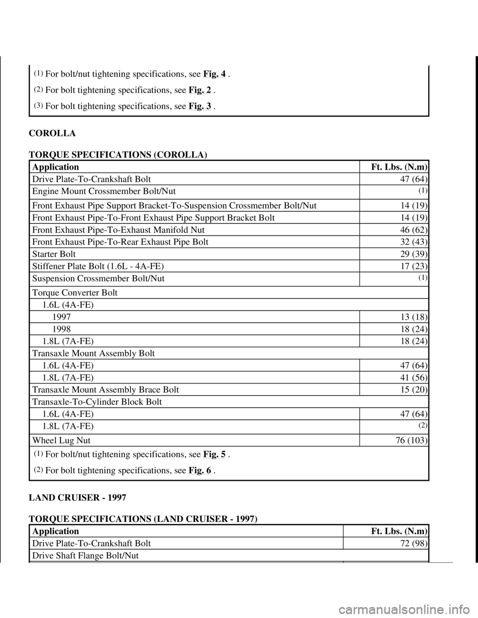
COROLLA
TORQUE SPECIFICATIONS (COROLLA)
LAND CRUISER - 1997
TORQUE SPECIFICATIONS (LAND CRUISER - 1997)
(1)For bolt/nut tightening specifications, see Fig. 4 .
(2)For bolt tightening specifications, see Fig. 2 .
(3)For bolt tightening specifications, see Fig. 3 .
ApplicationFt. Lbs. (N.m)
Drive Plate-To-Crankshaft Bolt47 (64)
Engine Mount Crossmember Bolt/Nut(1)
Front Exhaust Pipe Support Bracket-To-Suspension Crossmember Bolt/Nut14 (19)
Front Exhaust Pipe-To-Front Exhaust Pipe Support Bracket Bolt14 (19)
Front Exhaust Pipe-To-Exhaust Manifold Nut46 (62)
Front Exhaust Pipe-To-Rear Exhaust Pipe Bolt32 (43)
Starter Bolt29 (39)
Stiffener Plate Bolt (1.6L - 4A-FE)17 (23)
Suspension Crossmember Bolt/Nut(1)
Torque Converter Bolt
1.6L (4A-FE)
199713 (18)
199818 (24)
1.8L (7A-FE)18 (24)
Transaxle Mount Assembly Bolt
1.6L (4A-FE)47 (64)
1.8L (7A-FE)41 (56)
Transaxle Mount Assembly Brace Bolt15 (20)
Transaxle-To-Cylinder Block Bolt
1.6L (4A-FE)47 (64)
1.8L (7A-FE)(2)
Wheel Lug Nut76 (103)
(1)For bolt/nut tightening specifications, see Fig. 5 .
(2)For bolt tightening specifications, see Fig. 6 .
ApplicationFt. Lbs. (N.m)
Drive Plate-To-Crankshaft Bolt72 (98)
Drive Shaft Flange Bolt/Nut
1998 Toyota Avalon XLS
TRANSMISSION SERVICING - A/T 1997-98 TRANSMISSION SERVICING Toyota - Transmission Removal &
Installation
Helpmelearn
November-03-08 10:30:29 AMPage 35 © 2005 Mitchell Repair Information Company, LLC.
Page 150 of 1632
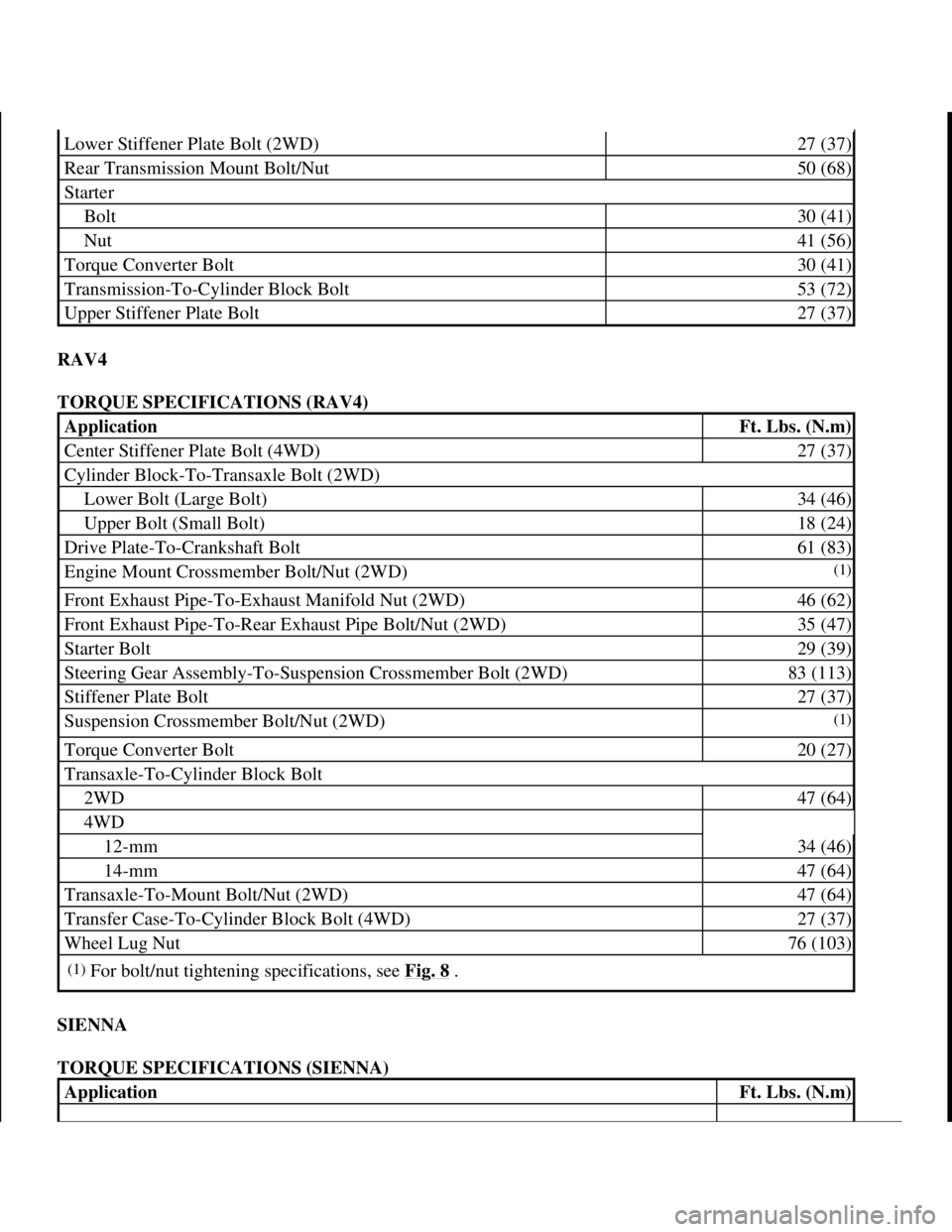
RAV4
TORQUE SPECIFICATIONS (RAV4)
SIENNA
TORQUE SPECIFICATIONS (SIENNA)
Lower Stiffener Plate Bolt (2WD)27 (37)
Rear Transmission Mount Bolt/Nut50 (68)
Starter
Bolt30 (41)
Nut41 (56)
Torque Converter Bolt30 (41)
Transmission-To-Cylinder Block Bolt53 (72)
Upper Stiffener Plate Bolt27 (37)
ApplicationFt. Lbs. (N.m)
Center Stiffener Plate Bolt (4WD)27 (37)
Cylinder Block-To-Transaxle Bolt (2WD)
Lower Bolt (Large Bolt)34 (46)
Upper Bolt (Small Bolt)18 (24)
Drive Plate-To-Crankshaft Bolt61 (83)
Engine Mount Crossmember Bolt/Nut (2WD)(1)
Front Exhaust Pipe-To-Exhaust Manifold Nut (2WD)46 (62)
Front Exhaust Pipe-To-Rear Exhaust Pipe Bolt/Nut (2WD)35 (47)
Starter Bolt29 (39)
Steering Gear Assembly-To-Suspension Crossmember Bolt (2WD)83 (113)
Stiffener Plate Bolt27 (37)
Suspension Crossmember Bolt/Nut (2WD)(1)
Torque Converter Bolt20 (27)
Transaxle-To-Cylinder Block Bolt
2WD47 (64)
4WD
12-mm34 (46)
14-mm47 (64)
Transaxle-To-Mount Bolt/Nut (2WD)47 (64)
Transfer Case-To-Cylinder Block Bolt (4WD)27 (37)
Wheel Lug Nut76 (103)
(1)For bolt/nut tightening specifications, see Fig. 8 .
ApplicationFt. Lbs. (N.m)
1998 Toyota Avalon XLS
TRANSMISSION SERVICING - A/T 1997-98 TRANSMISSION SERVICING Toyota - Transmission Removal &
Installation
Helpmelearn
November-03-08 10:30:29 AMPage 38 © 2005 Mitchell Repair Information Company, LLC.
Page 322 of 1632
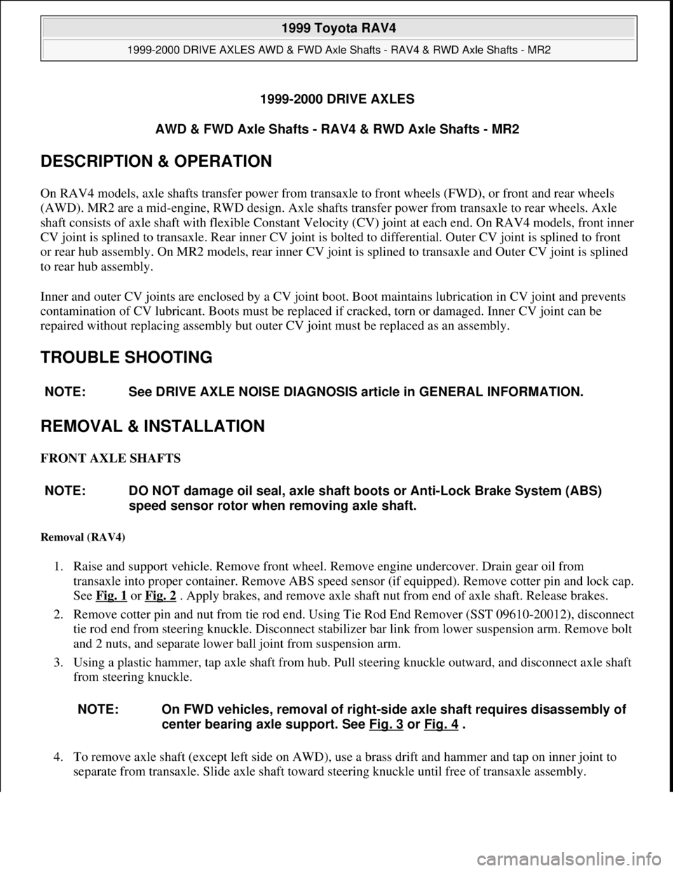
1999-2000 DRIVE AXLES
AWD & FWD Axle Shafts - RAV4 & RWD Axle Shafts - MR2
DESCRIPTION & OPERATION
On RAV4 models, axle shafts transfer power from transaxle to front wheels (FWD), or front and rear wheels
(AWD). MR2 are a mid-engine, RWD design. Axle shafts transfer power from transaxle to rear wheels. Axle
shaft consists of axle shaft with flexible Constant Velocity (CV) joint at each end. On RAV4 models, front inner
CV joint is splined to transaxle. Rear inner CV joint is bolted to differential. Outer CV joint is splined to front
or rear hub assembly. On MR2 models, rear inner CV joint is splined to transaxle and Outer CV joint is splined
to rear hub assembly.
Inner and outer CV joints are enclosed by a CV joint boot. Boot maintains lubrication in CV joint and prevents
contamination of CV lubricant. Boots must be replaced if cracked, torn or damaged. Inner CV joint can be
repaired without replacing assembly but outer CV joint must be replaced as an assembly.
TROUBLE SHOOTING
REMOVAL & INSTALLATION
FRONT AXLE SHAFTS
Removal (RAV4)
1. Raise and support vehicle. Remove front wheel. Remove engine undercover. Drain gear oil from
transaxle into proper container. Remove ABS speed sensor (if equipped). Remove cotter pin and lock cap.
See Fig. 1
or Fig. 2 . Apply brakes, and remove axle shaft nut from end of axle shaft. Release brakes.
2. Remove cotter pin and nut from tie rod end. Using Tie Rod End Remover (SST 09610-20012), disconnect
tie rod end from steering knuckle. Disconnect stabilizer bar link from lower suspension arm. Remove bolt
and 2 nuts, and separate lower ball joint from suspension arm.
3. Using a plastic hammer, tap axle shaft from hub. Pull steering knuckle outward, and disconnect axle shaft
from steering knuckle.
4. To remove axle shaft (except left side on AWD), use a brass drift and hammer and tap on inner joint to
separate from transaxle. Slide axle shaft toward steering knuckle until free of transaxle assembly. NOTE: See DRIVE AXLE NOISE DIAGNOSIS article in GENERAL INFORMATION.
NOTE: DO NOT damage oil seal, axle shaft boots or Anti-Lock Brake System (ABS)
speed sensor rotor when removing axle shaft.
NOTE: On FWD vehicles, removal of right-side axle shaft requires disassembly of
center bearing axle support. See Fig. 3
or Fig. 4 .
1999 Toyota RAV4
1999-2000 DRIVE AXLES AWD & FWD Axle Shafts - RAV4 & RWD Axle Shafts - MR2
1999 Toyota RAV4
1999-2000 DRIVE AXLES AWD & FWD Axle Shafts - RAV4 & RWD Axle Shafts - MR2
Microsoft
Sunday, November 22, 2009 10:08:21 AMPage 1 © 2005 Mitchell Repair Information Company, LLC.
Microsoft
Sunday, November 22, 2009 10:08:25 AMPage 1 © 2005 Mitchell Repair Information Company, LLC.