washer fluid TOYOTA RAV4 1996 Service Repair Manual
[x] Cancel search | Manufacturer: TOYOTA, Model Year: 1996, Model line: RAV4, Model: TOYOTA RAV4 1996Pages: 1632, PDF Size: 41.64 MB
Page 128 of 1632

clutch, fan shroud and radiator. Remove transmission dipstick. Remove dipstick tube upper bolt.
Disconnect 2 bleeder hoses.
2. Remove knob from transfer case shift lever. Remove upper console panel. Remove 4 boots to transfer
shift lever boot and remove shift lever boot. Raise and support vehicle. Remove 2 lower engine covers.
Remove exhaust pipes as necessary. Place reference marks on drive shaft flanges for reassembly
reference. Remove bolts and all drive shafts.
3. Remove dipstick tube lower bolt. Remove dipstick tube and "O" ring. Remove nut and plate washer, and
disconnect transmission shift control rod. Remove clip, plate washer and collar, and disconnect transfer
shift lever rod assembly. Disconnect all necessary electrical connectors for transmission and transfer case
removal. Remove 2 bolts and cover from front of transmission for access to torque converter bolts.
Remove torque converter bolts. Remove oil cooler pipe union nuts and pipe bracket bolt from
transmission.
4. Support transmission with transmission jack. Remove 8 bolts and 2 nuts from crossmember and remove
crossmember. Lower rear of transmission. Remove transmission wire clamp bolt. Remove 10
transmission-to-cylinder block bolts. Lower transmission with transfer case from vehicle.
Installation
1. Before installing transmission, use dial indicator to check drive plate runout. Drive plate runout should be
checked right next to the starter ring gear on the drive plate. Replace drive plate if runout
exceeds .0079" (.200 mm).
2. Install torque converter on transmission. To ensure torque converter is fully seated, torque converter
depth should be checked. Using straightedge and caliper, measure torque converter depth from torque
converter bolt lug on torque converter to the surface on transmission. See Fig. 1
.
3. Torque converter depth should be more than .673" (17.10 mm). If torque converter depth is less than
specified, check for improperly seated torque converter.
4. To install, reverse removal procedure. Tighten all bolts/nuts to specification. See TORQUE
SPECIFICATIONS When installing torque converter bolts, apply Loctite to torque converter bolt
threads before installing. Ensure the Green torque converter bolt is installed first before installing the
remaining torque converter bolts.
5. Install NEW "O" ring on dipstick tube. Use NEW gaskets and NEW nuts when installing front exhaust
pipe. Fill cooling system and check for leaks. Adjust shift linkages and fill with ATF. See appropriate
TRANSMISSION SERVICING article.
Removal (Paseo)
1. Disconnect negative battery cable. Remove transaxle oil dipstick. Disconnect throttle valve cable from
throttle body. Remove air cleaner assembly along with air intake duct to air cleaner.
2. Remove upper bolt from starter. Remove the 2 upper transaxle-to-cylinder block bolts located at top of
transaxle. Raise and support vehicle. Remove lower engine covers.
3. Support engine with hoist. Remove front wheels. Drain transaxle fluid. Remove axle shafts from
transaxle. See FWD AXLE SHAFTS article in DRIVE AXLES.
4. Disconnect necessary electrical connectors, ground cables, speedometer cable, control cables and oil
cooler lines for transaxle removal. Remove the 2 vertical bottom bolts from front (radiator side) transaxle
mount.
1998 Toyota Avalon XLS
TRANSMISSION SERVICING - A/T 1997-98 TRANSMISSION SERVICING Toyota - Transmission Removal &
Installation
Helpmelearn
November-03-08 10:30:28 AMPage 16 © 2005 Mitchell Repair Information Company, LLC.
Page 134 of 1632
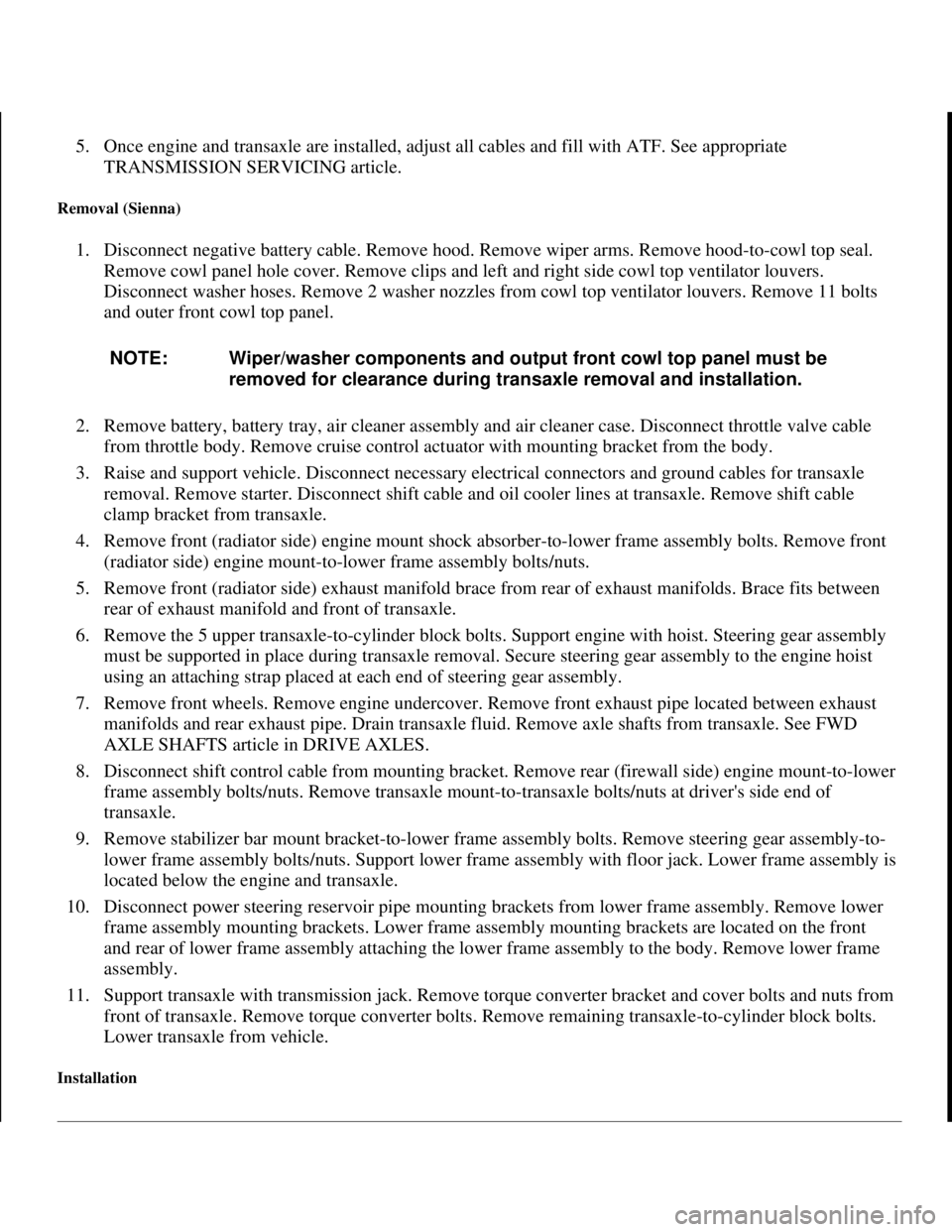
5. Once engine and transaxle are installed, adjust all cables and fill with ATF. See appropriate
TRANSMISSION SERVICING article.
Removal (Sienna)
1. Disconnect negative battery cable. Remove hood. Remove wiper arms. Remove hood-to-cowl top seal.
Remove cowl panel hole cover. Remove clips and left and right side cowl top ventilator louvers.
Disconnect washer hoses. Remove 2 washer nozzles from cowl top ventilator louvers. Remove 11 bolts
and outer front cowl top panel.
2. Remove battery, battery tray, air cleaner assembly and air cleaner case. Disconnect throttle valve cable
from throttle body. Remove cruise control actuator with mounting bracket from the body.
3. Raise and support vehicle. Disconnect necessary electrical connectors and ground cables for transaxle
removal. Remove starter. Disconnect shift cable and oil cooler lines at transaxle. Remove shift cable
clamp bracket from transaxle.
4. Remove front (radiator side) engine mount shock absorber-to-lower frame assembly bolts. Remove front
(radiator side) engine mount-to-lower frame assembly bolts/nuts.
5. Remove front (radiator side) exhaust manifold brace from rear of exhaust manifolds. Brace fits between
rear of exhaust manifold and front of transaxle.
6. Remove the 5 upper transaxle-to-cylinder block bolts. Support engine with hoist. Steering gear assembly
must be supported in place during transaxle removal. Secure steering gear assembly to the engine hoist
using an attaching strap placed at each end of steering gear assembly.
7. Remove front wheels. Remove engine undercover. Remove front exhaust pipe located between exhaust
manifolds and rear exhaust pipe. Drain transaxle fluid. Remove axle shafts from transaxle. See FWD
AXLE SHAFTS article in DRIVE AXLES.
8. Disconnect shift control cable from mounting bracket. Remove rear (firewall side) engine mount-to-lower
frame assembly bolts/nuts. Remove transaxle mount-to-transaxle bolts/nuts at driver's side end of
transaxle.
9. Remove stabilizer bar mount bracket-to-lower frame assembly bolts. Remove steering gear assembly-to-
lower frame assembly bolts/nuts. Support lower frame assembly with floor jack. Lower frame assembly is
located below the engine and transaxle.
10. Disconnect power steering reservoir pipe mounting brackets from lower frame assembly. Remove lower
frame assembly mounting brackets. Lower frame assembly mounting brackets are located on the front
and rear of lower frame assembly attaching the lower frame assembly to the body. Remove lower frame
assembly.
11. Support transaxle with transmission jack. Remove torque converter bracket and cover bolts and nuts from
front of transaxle. Remove torque converter bolts. Remove remaining transaxle-to-cylinder block bolts.
Lower transaxle from vehicle.
Installation
NOTE: Wiper/washer components and output front cowl top panel must be
removed for clearance during transaxle removal and installation.
1998 Toyota Avalon XLS
TRANSMISSION SERVICING - A/T 1997-98 TRANSMISSION SERVICING Toyota - Transmission Removal &
Installation
Helpmelearn
November-03-08 10:30:29 AMPage 22 © 2005 Mitchell Repair Information Company, LLC.
Page 355 of 1632
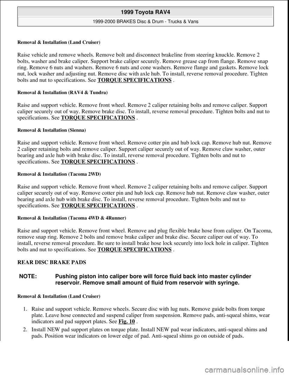
Removal & Installation (Land Cruiser)
Raise vehicle and remove wheels. Remove bolt and disconnect brakeline from steering knuckle. Remove 2
bolts, washer and brake caliper. Support brake caliper securely. Remove grease cap from flange. Remove snap
ring. Remove 6 nuts and washers. Remove 6 nuts and cone washers. Remove flange and gaskets. Remove lock
nut, lock washer and adjusting nut. Remove disc with axle hub. To install, reverse removal procedure. Tighten
bolts and nut to specifications. See TORQUE SPECIFICATIONS
.
Removal & Installation (RAV4 & Tundra)
Raise and support vehicle. Remove front wheel. Remove 2 caliper retaining bolts and remove caliper. Support
caliper securely out of way. Remove brake disc. To install, reverse removal procedure. Tighten bolts and nut to
specifications. See TORQUE SPECIFICATIONS
.
Removal & Installation (Sienna)
Raise and support vehicle. Remove front wheel. Remove cotter pin and hub lock cap. Remove hub nut. Remove
2 caliper retaining bolts and remove caliper. Support caliper securely out of way. Remove claw washer, outer
bearing and axle hub with brake disc. To install, reverse removal procedure. Tighten bolts and nut to
specifications. See TORQUE SPECIFICATIONS
.
Removal & Installation (Tacoma 2WD)
Raise and support vehicle. Remove front wheel. Remove 2 caliper retaining bolts and remove caliper. Support
caliper securely out of way. Remove cotter pin and hub lock cap. Remove hub nut. Remove claw washer, outer
bearing and axle hub with brake disc. To install, reverse removal procedure. Tighten bolts and nut to
specifications. See TORQUE SPECIFICATIONS
.
Removal & Installation (Tacoma 4WD & 4Runner)
Raise and support vehicle. Remove front wheel. Remove and plug flexible brake hose from caliper. On Tacoma,
remove snap ring. Remove 2 bolts and remove brake caliper and brake disc. Secure caliper out of way. To
install, reverse removal procedure. Be sure to install brake hose lock securely into lock hole in caliper. Tighten
bolts and nut to specifications. See TORQUE SPECIFICATIONS
.
REAR DISC BRAKE PADS
Removal & Installation (Land Cruiser)
1. Raise and support vehicle. Remove wheels. Secure disc with lug nuts. Remove guide bolts from torque
plate. Leave hose connected and suspend caliper from suspension. Remove pads, anti-squeal shims, wear
indicators and pad support plates. See Fig. 10
.
2. Install NEW pad support plates on torque plate. Install NEW pad wear indicators, anti-squeal shims and
pads. Position wear indicators on lower edge of pad. Anti-squeal shims go on outside of pads. NOTE: Pushing piston into caliper bore will force fluid back into master cylinder
reservoir. Remove small amount of fluid from reservoir with syringe.
1999 Toyota RAV4
1999-2000 BRAKES Disc & Drum - Trucks & Vans
Microsoft
Sunday, November 22, 2009 10:07:28 AMPage 16 © 2005 Mitchell Repair Information Company, LLC.
Page 606 of 1632
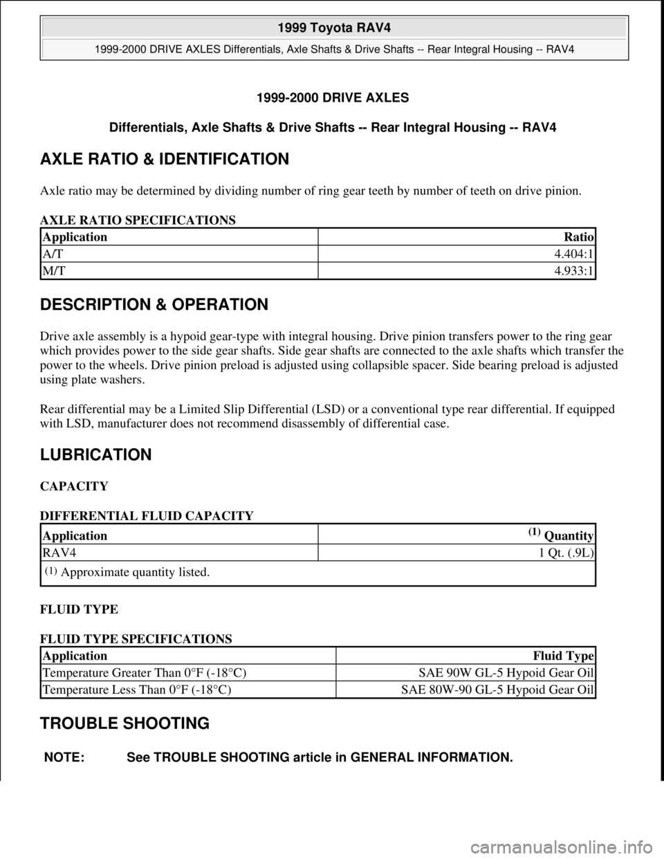
1999-2000 DRIVE AXLES
Differentials, Axle Shafts & Drive Shafts -- Rear Integral Housing -- RAV4
AXLE RATIO & IDENTIFICATION
Axle ratio may be determined by dividing number of ring gear teeth by number of teeth on drive pinion.
AXLE RATIO SPECIFICATIONS
DESCRIPTION & OPERATION
Drive axle assembly is a hypoid gear-type with integral housing. Drive pinion transfers power to the ring gear
which provides power to the side gear shafts. Side gear shafts are connected to the axle shafts which transfer the
power to the wheels. Drive pinion preload is adjusted using collapsible spacer. Side bearing preload is adjusted
using plate washers.
Rear differential may be a Limited Slip Differential (LSD) or a conventional type rear differential. If equipped
with LSD, manufacturer does not recommend disassembly of differential case.
LUBRICATION
CAPACITY
DIFFERENTIAL FLUID CAPACITY
FLUID TYPE
FLUID TYPE SPECIFICATIONS
TROUBLE SHOOTING
ApplicationRatio
A/T4.404:1
M/T4.933:1
Application(1) Quantity
RAV41 Qt. (.9L)
(1)Approximate quantity listed.
ApplicationFluid Type
Temperature Greater Than 0°F (-18°C)SAE 90W GL-5 Hypoid Gear Oil
Temperature Less Than 0°F (-18°C)SAE 80W-90 GL-5 Hypoid Gear Oil
NOTE: See TROUBLE SHOOTING article in GENERAL INFORMATION.
1999 Toyota RAV4
1999-2000 DRIVE AXLES Differentials, Axle Shafts & Drive Shafts -- Rear Integral Housing -- RAV4
1999 Toyota RAV4
1999-2000 DRIVE AXLES Differentials, Axle Shafts & Drive Shafts -- Rear Integral Housing -- RAV4
Microsoft
Sunday, November 22, 2009 10:09:38 AMPage 1 © 2005 Mitchell Repair Information Company, LLC.
Microsoft
Sunday, November 22, 2009 10:09:42 AMPage 1 © 2005 Mitchell Repair Information Company, LLC.
Page 675 of 1632
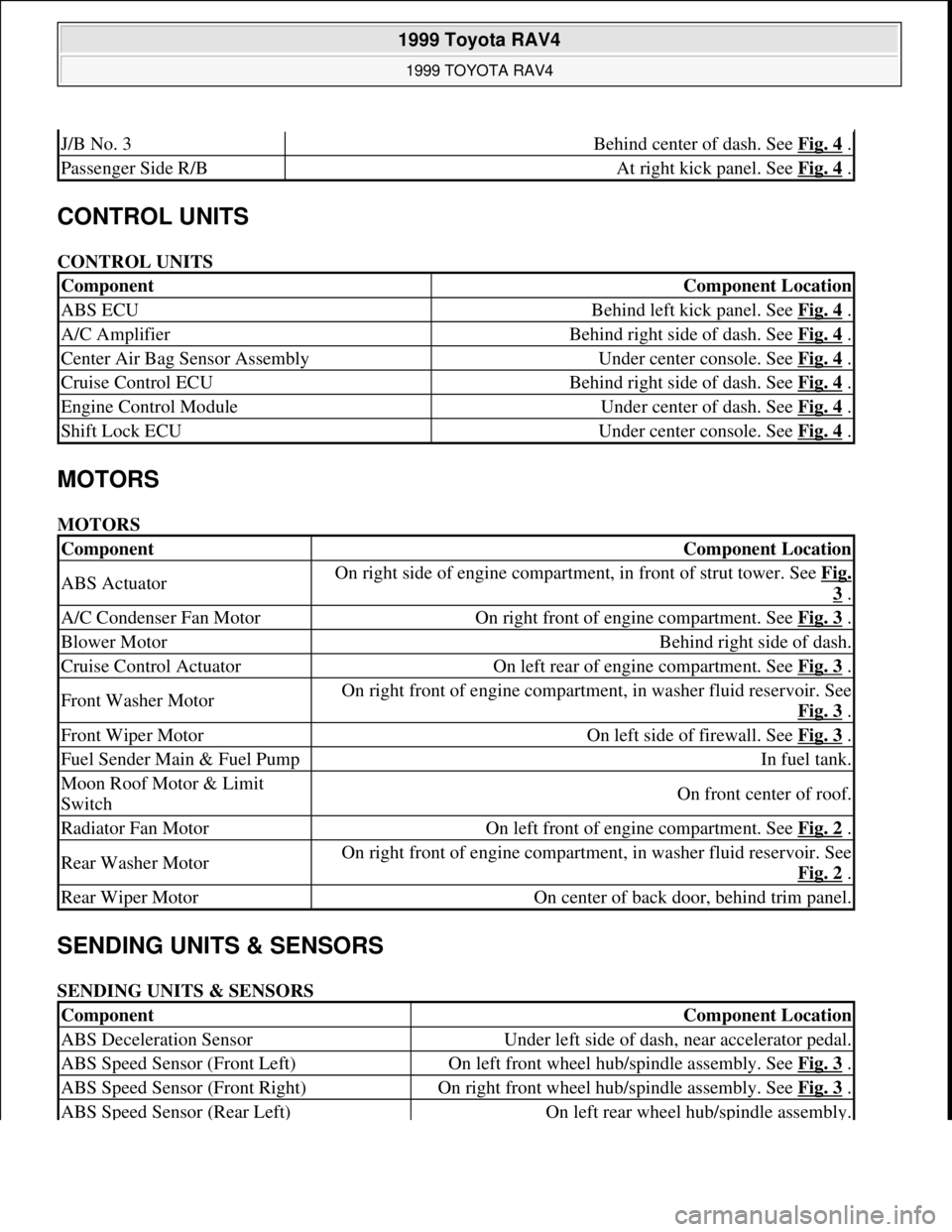
CONTROL UNITS
CONTROL UNITS
MOTORS
MOTORS
SENDING UNITS & SENSORS
SENDING UNITS & SENSORS
J/B No. 3Behind center of dash. See Fig. 4 .
Passenger Side R/BAt right kick panel. See Fig. 4 .
ComponentComponent Location
ABS ECUBehind left kick panel. See Fig. 4 .
A/C AmplifierBehind right side of dash. See Fig. 4 .
Center Air Bag Sensor AssemblyUnder center console. See Fig. 4 .
Cruise Control ECUBehind right side of dash. See Fig. 4 .
Engine Control ModuleUnder center of dash. See Fig. 4 .
Shift Lock ECUUnder center console. See Fig. 4 .
ComponentComponent Location
ABS ActuatorOn right side of engine compartment, in front of strut tower. See Fig.
3 .
A/C Condenser Fan MotorOn right front of engine compartment. See Fig. 3 .
Blower MotorBehind right side of dash.
Cruise Control ActuatorOn left rear of engine compartment. See Fig. 3 .
Front Washer MotorOn right front of engine compartment, in washer fluid reservoir. See
Fig. 3
.
Front Wiper MotorOn left side of firewall. See Fig. 3 .
Fuel Sender Main & Fuel PumpIn fuel tank.
Moon Roof Motor & Limit
SwitchOn front center of roof.
Radiator Fan MotorOn left front of engine compartment. See Fig. 2 .
Rear Washer MotorOn right front of engine compartment, in washer fluid reservoir. See
Fig. 2
.
Rear Wiper MotorOn center of back door, behind trim panel.
ComponentComponent Location
ABS Deceleration SensorUnder left side of dash, near accelerator pedal.
ABS Speed Sensor (Front Left)On left front wheel hub/spindle assembly. See Fig. 3 .
ABS Speed Sensor (Front Right)On right front wheel hub/spindle assembly. See Fig. 3 .
ABS Speed Sensor (Rear Left)On left rear wheel hub/spindle assembly.
1999 Toyota RAV4
1999 TOYOTA RAV4
Microsoft
Sunday, November 22, 2009 10:17:32 AMPage 2 © 2005 Mitchell Repair Information Company, LLC.
Page 676 of 1632
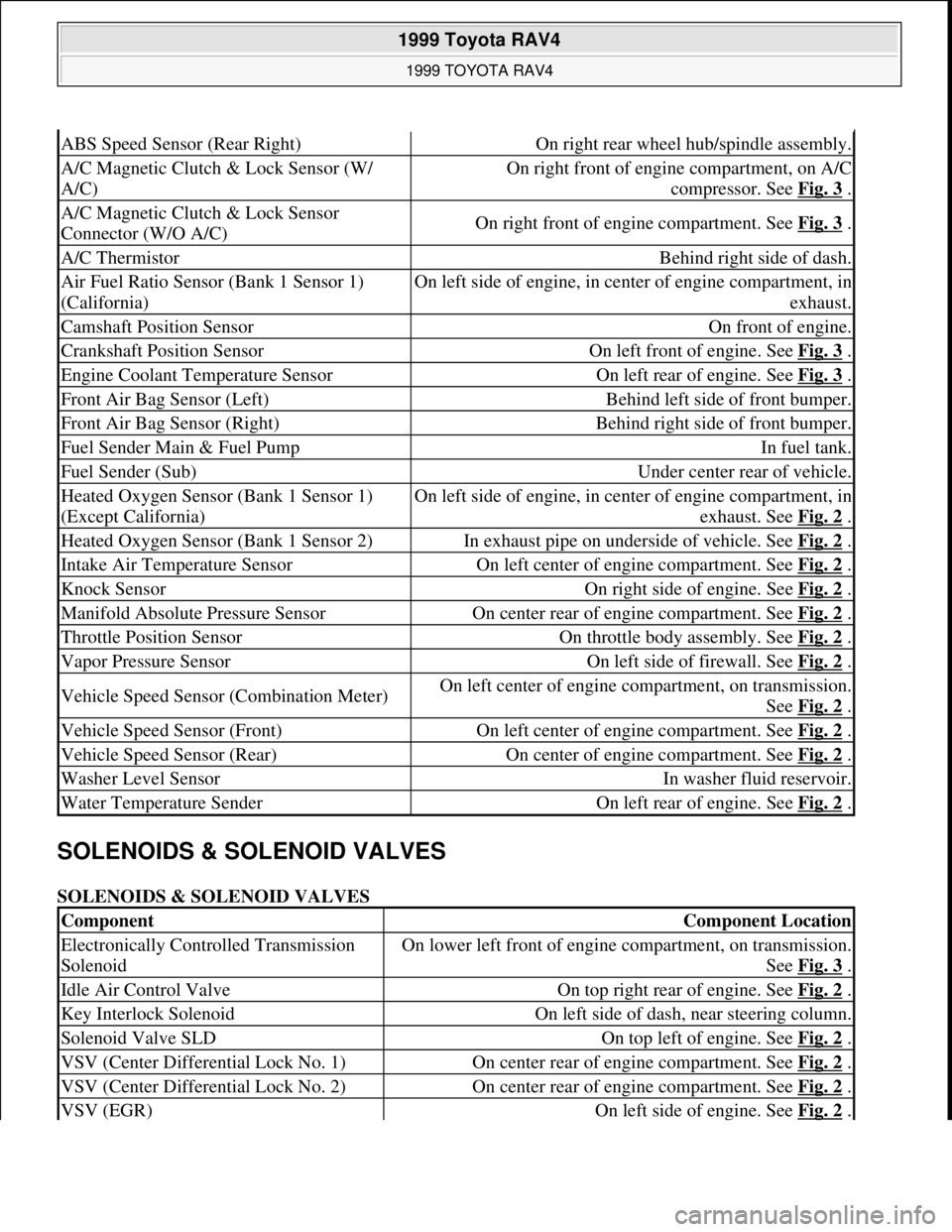
SOLENOIDS & SOLENOID VALVES
SOLENOIDS & SOLENOID VALVES
ABS Speed Sensor (Rear Right)On right rear wheel hub/spindle assembly.
A/C Magnetic Clutch & Lock Sensor (W/
A/C)On right front of engine compartment, on A/C
compressor. See Fig. 3
.
A/C Magnetic Clutch & Lock Sensor
Connector (W/O A/C)On right front of engine compartment. See Fig. 3 .
A/C ThermistorBehind right side of dash.
Air Fuel Ratio Sensor (Bank 1 Sensor 1)
(California)On left side of engine, in center of engine compartment, in
exhaust.
Camshaft Position SensorOn front of engine.
Crankshaft Position SensorOn left front of engine. See Fig. 3 .
Engine Coolant Temperature SensorOn left rear of engine. See Fig. 3 .
Front Air Bag Sensor (Left)Behind left side of front bumper.
Front Air Bag Sensor (Right)Behind right side of front bumper.
Fuel Sender Main & Fuel PumpIn fuel tank.
Fuel Sender (Sub)Under center rear of vehicle.
Heated Oxygen Sensor (Bank 1 Sensor 1)
(Except California)On left side of engine, in center of engine compartment, in
exhaust. See Fig. 2
.
Heated Oxygen Sensor (Bank 1 Sensor 2)In exhaust pipe on underside of vehicle. See Fig. 2 .
Intake Air Temperature SensorOn left center of engine compartment. See Fig. 2 .
Knock SensorOn right side of engine. See Fig. 2 .
Manifold Absolute Pressure SensorOn center rear of engine compartment. See Fig. 2 .
Throttle Position SensorOn throttle body assembly. See Fig. 2 .
Vapor Pressure SensorOn left side of firewall. See Fig. 2 .
Vehicle Speed Sensor (Combination Meter)On left center of engine compartment, on transmission.
See Fig. 2
.
Vehicle Speed Sensor (Front)On left center of engine compartment. See Fig. 2 .
Vehicle Speed Sensor (Rear)On center of engine compartment. See Fig. 2 .
Washer Level SensorIn washer fluid reservoir.
Water Temperature SenderOn left rear of engine. See Fig. 2 .
ComponentComponent Location
Electronically Controlled Transmission
SolenoidOn lower left front of engine compartment, on transmission.
See Fig. 3
.
Idle Air Control ValveOn top right rear of engine. See Fig. 2 .
Key Interlock SolenoidOn left side of dash, near steering column.
Solenoid Valve SLDOn top left of engine. See Fig. 2 .
VSV (Center Differential Lock No. 1)On center rear of engine compartment. See Fig. 2 .
VSV (Center Differential Lock No. 2)On center rear of engine compartment. See Fig. 2 .
VSV (EGR)On left side of engine. See Fig. 2 .
1999 Toyota RAV4
1999 TOYOTA RAV4
Microsoft
Sunday, November 22, 2009 10:17:32 AMPage 3 © 2005 Mitchell Repair Information Company, LLC.
Page 1104 of 1632
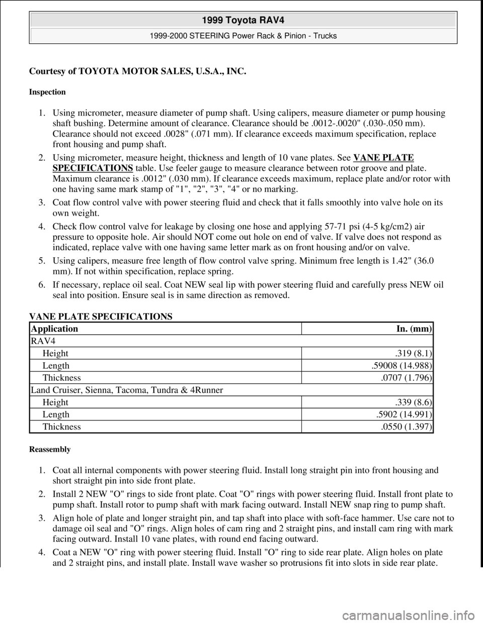
Courtesy of TOYOTA MOTOR SALES, U.S.A., INC.
Inspection
1. Using micrometer, measure diameter of pump shaft. Using calipers, measure diameter or pump housing
shaft bushing. Determine amount of clearance. Clearance should be .0012-.0020" (.030-.050 mm).
Clearance should not exceed .0028" (.071 mm). If clearance exceeds maximum specification, replace
front housing and pump shaft.
2. Using micrometer, measure height, thickness and length of 10 vane plates. See VANE PLATE
SPECIFICATIONS table. Use feeler gauge to measure clearance between rotor groove and plate.
Maximum clearance is .0012" (.030 mm). If clearance exceeds maximum, replace plate and/or rotor with
one having same mark stamp of "1", "2", "3", "4" or no marking.
3. Coat flow control valve with power steering fluid and check that it falls smoothly into valve hole on its
own weight.
4. Check flow control valve for leakage by closing one hose and applying 57-71 psi (4-5 kg/cm2) air
pressure to opposite hole. Air should NOT come out hole on end of valve. If valve does not respond as
indicated, replace valve with one having same letter mark as on front housing and/or on valve.
5. Using calipers, measure free length of flow control valve spring. Minimum free length is 1.42" (36.0
mm). If not within specification, replace spring.
6. If necessary, replace oil seal. Coat NEW seal lip with power steering fluid and carefully press NEW oil
seal into position. Ensure seal is in same direction as removed.
VANE PLATE SPECIFICATIONS
Reassembly
1. Coat all internal components with power steering fluid. Install long straight pin into front housing and
short straight pin into side front plate.
2. Install 2 NEW "O" rings to side front plate. Coat "O" rings with power steering fluid. Install front plate to
pump shaft. Install rotor to pump shaft with mark facing outward. Install NEW snap ring to pump shaft.
3. Align hole of plate and longer straight pin, and tap shaft into place with soft-face hammer. Use care not to
damage oil seal and "O" rings. Align holes of cam ring and 2 straight pins, and install cam ring with mark
facing outward. Install 10 vane plates, with round end facing outward.
4. Coat a NEW "O" ring with power steering fluid. Install "O" ring to side rear plate. Align holes on plate
and 2 straight pins, and install plate. Install wave washer so protrusions fit into slots in side rear plate.
ApplicationIn. (mm)
RAV4
Height.319 (8.1)
Length.59008 (14.988)
Thickness.0707 (1.796)
Land Cruiser, Sienna, Tacoma, Tundra & 4Runner
Height.339 (8.6)
Length.5902 (14.991)
Thickness.0550 (1.397)
1999 Toyota RAV4
1999-2000 STEERING Power Rack & Pinion - Trucks
Microsoft
Sunday, November 22, 2009 10:35:46 AMPage 11 © 2005 Mitchell Repair Information Company, LLC.
Page 1105 of 1632
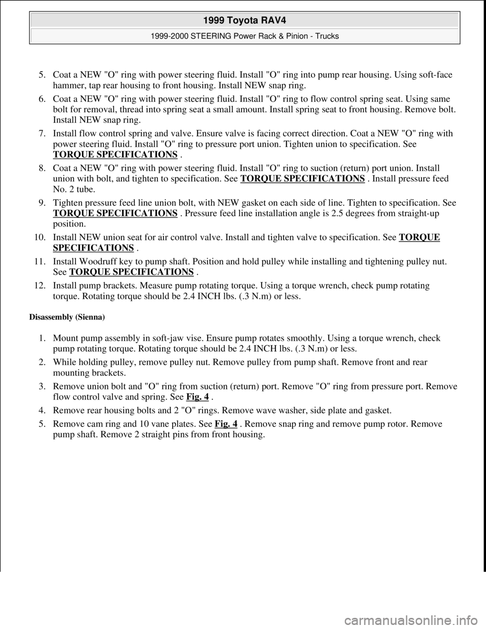
5. Coat a NEW "O" ring with power steering fluid. Install "O" ring into pump rear housing. Using soft-face
hammer, tap rear housing to front housing. Install NEW snap ring.
6. Coat a NEW "O" ring with power steering fluid. Install "O" ring to flow control spring seat. Using same
bolt for removal, thread into spring seat a small amount. Install spring seat to front housing. Remove bolt.
Install NEW snap ring.
7. Install flow control spring and valve. Ensure valve is facing correct direction. Coat a NEW "O" ring with
power steering fluid. Install "O" ring to pressure port union. Tighten union to specification. See
TORQUE SPECIFICATIONS
.
8. Coat a NEW "O" ring with power steering fluid. Install "O" ring to suction (return) port union. Install
union with bolt, and tighten to specification. See TORQUE SPECIFICATIONS
. Install pressure feed
No. 2 tube.
9. Tighten pressure feed line union bolt, with NEW gasket on each side of line. Tighten to specification. See
TORQUE SPECIFICATIONS
. Pressure feed line installation angle is 2.5 degrees from straight-up
position.
10. Install NEW union seat for air control valve. Install and tighten valve to specification. See TORQUE
SPECIFICATIONS .
11. Install Woodruff key to pump shaft. Position and hold pulley while installing and tightening pulley nut.
See TORQUE SPECIFICATIONS
.
12. Install pump brackets. Measure pump rotating torque. Using a torque wrench, check pump rotating
torque. Rotating torque should be 2.4 INCH lbs. (.3 N.m) or less.
Disassembly (Sienna)
1. Mount pump assembly in soft-jaw vise. Ensure pump rotates smoothly. Using a torque wrench, check
pump rotating torque. Rotating torque should be 2.4 INCH lbs. (.3 N.m) or less.
2. While holding pulley, remove pulley nut. Remove pulley from pump shaft. Remove front and rear
mounting brackets.
3. Remove union bolt and "O" ring from suction (return) port. Remove "O" ring from pressure port. Remove
flow control valve and spring. See Fig. 4
.
4. Remove rear housing bolts and 2 "O" rings. Remove wave washer, side plate and gasket.
5. Remove cam ring and 10 vane plates. See Fig. 4
. Remove snap ring and remove pump rotor. Remove
pump shaft. Remove 2 straight pins from front housing.
1999 Toyota RAV4
1999-2000 STEERING Power Rack & Pinion - Trucks
Microsoft
Sunday, November 22, 2009 10:35:46 AMPage 12 © 2005 Mitchell Repair Information Company, LLC.
Page 1107 of 1632
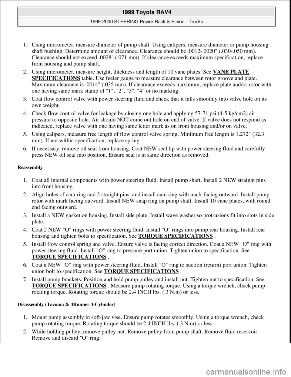
1. Using micrometer, measure diameter of pump shaft. Using calipers, measure diameter or pump housing
shaft bushing. Determine amount of clearance. Clearance should be .0012-.0020" (.030-.050 mm).
Clearance should not exceed .0028" (.071 mm). If clearance exceeds maximum specification, replace
front housing and pump shaft.
2. Using micrometer, measure height, thickness and length of 10 vane plates. See VANE PLATE
SPECIFICATIONS table. Use feeler gauge to measure clearance between rotor groove and plate.
Maximum clearance is .0014" (.035 mm). If clearance exceeds maximum, replace plate and/or rotor with
one having same mark stamp of "1", "2", "3", "4" or no marking.
3. Coat flow control valve with power steering fluid and check that it falls smoothly into valve hole on its
own weight.
4. Check flow control valve for leakage by closing one hole and applying 57-71 psi (4-5 kg/cm2) air
pressure to opposite hole. Air should NOT come out hole on end of valve. If valve does not respond as
indicated, replace valve with one having same letter mark as on front housing and/or on valve.
5. Using calipers, measure free length of flow control valve spring. Minimum free length is 1.272" (32.3
mm). If not within specification, replace spring.
6. If necessary, remove oil seal from housing. Coat NEW seal lip with power steering fluid and carefully
press NEW oil seal into position. Ensure seal is in same direction as removed.
Reassembly
1. Coat all internal components with power steering fluid. Install pump shaft. Install 2 NEW straight pins
into front housing.
2. Align holes of cam ring and 2 straight pins, and install cam ring with mark facing outward. Install pump
rotor with mark facing outward. Install NEW snap ring on pump shaft. Install 10 vane plates, with round
end facing outward.
3. Install a NEW gasket on housing. Install side plate. Install wave washer so protrusions fit into slots in side
plate.
4. Coat 2 NEW "O" rings with power steering fluid. Install "O" rings into pump rear housing. Install rear
housing and tighten bolts to specification. See TORQUE SPECIFICATIONS
.
5. Install flow control spring and valve. Ensure valve is facing correct direction. Coat a NEW "O" ring with
power steering fluid. Install "O" ring to pressure port union. Tighten union to specification. See
TORQUE SPECIFICATIONS
.
6. Coat a NEW "O" ring with power steering fluid. Install "O" ring to suction (return) port union. Tighten
union bolt to specification. See TORQUE SPECIFICATIONS
.
7. Install pump brackets. Position and hold pump pulley and install nut. Tighten nut to specification. See
TORQUE SPECIFICATIONS
. Measure pump rotating torque. Using a torque wrench, check pump
rotating torque. Rotating torque should be 2.4 INCH lbs. (.3 N.m) or less.
Disassembly (Tacoma & 4Runner 4-Cylinder)
1. Mount pump assembly in soft-jaw vise. Ensure pump rotates smoothly. Using a torque wrench, check
pump rotating torque. Rotating torque should be 2.4 INCH lbs. (.3 N.m) or less.
2. While holding pulley, remove pulley nut. Remove pulley from pump shaft. Remove fluid reservoir.
Remove and discard "O" ring.
1999 Toyota RAV4
1999-2000 STEERING Power Rack & Pinion - Trucks
Microsoft
Sunday, November 22, 2009 10:35:46 AMPage 14 © 2005 Mitchell Repair Information Company, LLC.
Page 1110 of 1632
1. Using micrometer, measure diameter of pump shaft. Using calipers, measure diameter or pump housing
shaft bushing. Determine amount of clearance. Clearance should be .0012-.0020" (.030-.050 mm).
Clearance should not exceed .0028" (.071 mm). If clearance exceeds maximum specification, replace
front housing and pump shaft.
2. Using micrometer, measure height, thickness and length of 10 vane plates. See VANE PLATE
SPECIFICATIONS table. Use feeler gauge to measure clearance between rotor groove and plate.
Maximum clearance is .0014" (.035 mm). If clearance exceeds maximum, replace plate and/or rotor with
one having same mark stamp of "1", "2", "3", "4" or no marking.
3. Coat flow control valve with power steering fluid, and check that it falls smoothly into valve hole on its
own weight.
4. Check flow control valve for leakage by closing one hose and applying 57-71 psi (4-5 kg/cm2) air
pressure to opposite hole. Air should NOT come out hole on end of valve. If valve does not respond as
indicated, replace valve with one having same letter mark as on front housing and/or on valve.
5. Using calipers, measure free length of flow control valve spring. Minimum free length is 1.307" (33.2
mm). If not within specification, replace spring.
6. If necessary, replace oil seal in front housing. Coat NEW seal lip with power steering fluid and carefully
press NEW oil seal into position. Ensure seal is in same direction as removed.
7. If necessary, replace pump shaft bearing. Press old bearing off of shaft. Remove snap ring. Install NEW
snap ring. Coat NEW bearing with power steering fluid. Press bearing onto shaft.
Reassembly
1. Coat all internal components with power steering fluid. Cover serrated part of shaft with vinyl tape. Press
pump shaft with bearing into housing. Install NEW snap ring in front housing. Install 2 NEW straight
pins into front housing.
2. Align holes of cam ring and 2 straight pins, and install cam ring with mark facing outward. Install pump
rotor with mark facing outward. Install NEW snap ring on pump shaft. Install 10 vane plates, with round
end facing outward.
3. Install a NEW gasket on front housing. Install side plate, aligning holes with straight pins. Install wave
washer so protrusions fit into slots in side plate.
4. Coat 2 NEW "O" rings with power steering fluid. Install "O" rings into pump rear housing. Install rear
housing and tighten bolts to specification. See TORQUE SPECIFICATIONS
.
5. Install flow control spring and valve. Ensure valve is facing correct direction. Coat a NEW "O" ring with
power steering fluid. Install "O" ring to pressure port union. Tighten union to specification. See
TORQUE SPECIFICATIONS
.
6. Install fluid reservoir with NEW "O" ring. Tighten bolts to specification. See TORQUE
SPECIFICATIONS .
7. Position and hold pump pulley, and install nut. Tighten nut to specification. See TORQUE
SPECIFICATIONS . Measure pump rotating torque. Using a torque wrench, check pump rotating
torque. Rotating torque should be 2.4 INCH lbs. (.3 N.m) or less.
Disassembly (Land Cruiser, Tacoma & 4Runner V6 & Tundra V6 & V8)
1. Mount pump assembly in soft-jaw vise. Ensure pump rotates smoothly. Using a torque wrench, check
1999 Toyota RAV4
1999-2000 STEERING Power Rack & Pinion - Trucks
Microsoft
Sunday, November 22, 2009 10:35:47 AMPage 17 © 2005 Mitchell Repair Information Company, LLC.