display TOYOTA RAV4 1996 Service Owner's Guide
[x] Cancel search | Manufacturer: TOYOTA, Model Year: 1996, Model line: RAV4, Model: TOYOTA RAV4 1996Pages: 1354, PDF Size: 30.43 MB
Page 627 of 1354

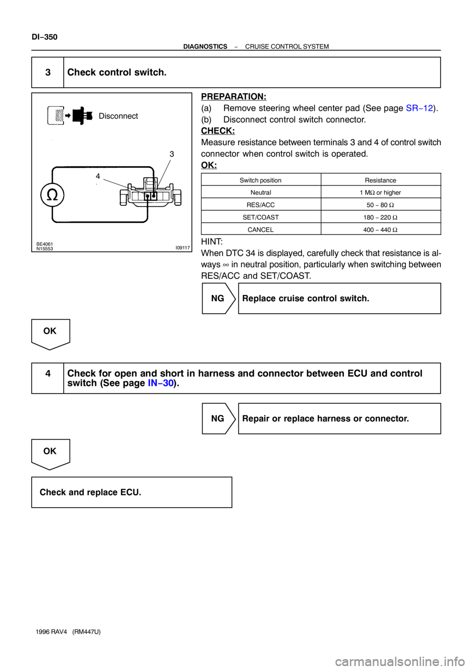
BE4061N15553I09117
43 Disconnect
DI−350
− DIAGNOSTICSCRUISE CONTROL SYSTEM
1996 RAV4 (RM447U)
3 Check control switch.
PREPARATION:
(a) Remove steering wheel center pad (See page SR−12).
(b) Disconnect control switch connector.
CHECK:
Measure resistance between terminals 3 and 4 of control switch
connector when control switch is operated.
OK:
Switch positionResistance
Neutral1 MΩ or higher
RES/ACC50 − 80 Ω
SET/COAST180 − 220 Ω
CANCEL400 − 440 Ω
HINT:
When DTC 34 is displayed, carefully check that resistance is al-
ways ∞ in neutral position, particularly when switching between
RES/ACC and SET/COAST.
NG Replace cruise control switch.
OK
4 Check for open and short in harness and connector between ECU and control
switch (See page IN−30).
NG Repair or replace harness or connector.
OK
Check and replace ECU.
Page 786 of 1354

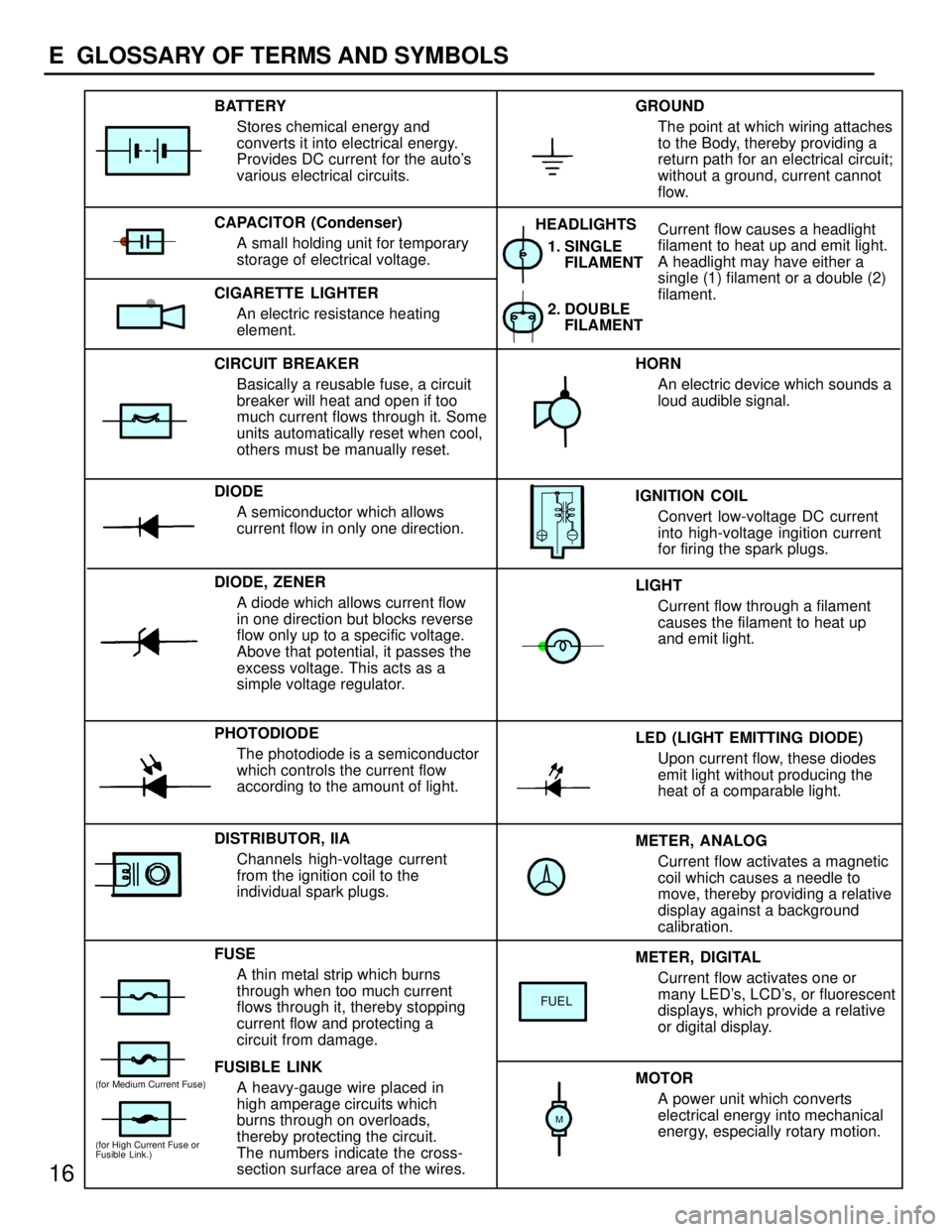
METER, ANALOG
Current flow activates a magnetic
coil which causes a needle to
move, thereby providing a relative
display against a background
calibration. LED (LIGHT EMITTING DIODE)
Upon current flow, these diodes
emit light without producing the
heat of a comparable light. IGNITION COIL
Convert low-voltage DC current
into high-voltage ingition current
for firing the spark plugs. 1. SINGLE
FILAMENT
GROUND
The point at which wiring attaches
to the Body, thereby providing a
return path for an electrical circuit;
without a ground, current cannot
flow.
Current flow causes a headlight
filament to heat up and emit light.
A headlight may have either a
single (1) filament or a double (2)
filament. BATTERY
Stores chemical energy and
converts it into electrical energy.
Provides DC current for the auto's
various electrical circuits.
CAPACITOR (Condenser)
A small holding unit for temporary
storage of electrical voltage.
CIRCUIT BREAKER
Basically a reusable fuse, a circuit
breaker will heat and open if too
much current flows through it. Some
units automatically reset when cool,
others must be manually reset.
DIODE
A semiconductor which allows
current flow in only one direction.
DIODE, ZENER
A diode which allows current flow
in one direction but blocks reverse
flow only up to a specific voltage.
Above that potential, it passes the
excess voltage. This acts as a
simple voltage regulator.
PHOTODIODE
The photodiode is a semiconductor
which controls the current flow
according to the amount of light.
FUSE
A thin metal strip which burns
through when too much current
flows through it, thereby stopping
current flow and protecting a
circuit from damage.
FUSIBLE LINK
A heavy-gauge wire placed in
high amperage circuits which
burns through on overloads,
thereby protecting the circuit.
The numbers indicate the cross-
section surface area of the wires.HORN
An electric device which sounds a
loud audible signal.
LIGHT
Current flow through a filament
causes the filament to heat up
and emit light.
METER, DIGITAL
Current flow activates one or
many LED's, LCD's, or fluorescent
displays, which provide a relative
or digital display.
MOTOR
A power unit which converts
electrical energy into mechanical
energy, especially rotary motion. CIGARETTE LIGHTER
An electric resistance heating
element.
DISTRIBUTOR, IIA
Channels high-voltage current
from the ignition coil to the
individual spark plugs.2. DOUBLE
FILAMENT HEADLIGHTS
FUEL
(for High Current Fuse or
Fusible Link.)
(for Medium Current Fuse)
M
16
E GLOSSARY OF TERMS AND SYMBOLS
Page 834 of 1354

65
2. CONTROL SYSTEM
*SFI
THE SFI SYSTEM MONITORS THE ENGINE CONDITION THROUGH THE SIGNALS, WHICH ARE INPUT FROM EACH SENSOR (INPUT
SIGNALS (1) TO (11)). THE BEST FUEL INJECTION VOLUME IS DECIDED BASED ON THIS DATA AND THE PROGRAM MEMORIZED
BY THE ENGINE CONTROL MODULE, AND THE CONTROL SIGNAL IS OUTPUT TO TERMINALS #10, #20, #30, AND #40 OF THE
ENGINE CONTROL MODULE TO OPERATE THE INJECTOR (INJECT THE FUEL). THE SFI SYSTEM PRODUCES CONTROL OF FUEL
INJECTION OPERATION BY THE ENGINE CONTROL MODULE IN RESPONSE TO THE DRIVING CONDITIONS.
*IDLE SPEED CONTROL SYSTEM
THE IDLE SPEED CONTROL SYSTEM INCREASES THE RPM AND PROVIDES IDLING STABILITY FOR FAST IDLE-UP WHEN THE
ENGINE IS COLD AND WHEN THE IDLE SPEED HAS DROPPED DUE TO ELECTRICAL LOAD, ETC. THE ENGINE CONTROL MODULE
EVALUATES THE SIGNALS FROM EACH SENSOR (INPUT SIGNALS (1 TO 5, 11), OUTPUTS CURRENT TO TERMINAL ISCO AND ISCC,
AND CONTROLS THE IDLE AIR CONTROL VALVE.
*A/C CUT CONTROL SYSTEM
WHEN THE VEHICLE SUDDENLY ACCELERATES FROM LOW ENGINE SPEED, THIS SYSTEM CUTS OFF AIR CONDITIONING
OPERATION FOR A FIXED PERIOD OF TIME IN RESPONSE TO THE SPEED SENSOR, THROTTLE VALVE OPENING ANGLE AND
INTAKE MANIFOLD PRESSURE IN ORDER TO MAINTAIN ACCELERATION PERFORMANCE.
THE ENGINE CONTROL MODULE RECEIVES INPUT SIGNALS (4, 5 AND 9), AND INPUTS SIGNALS TO TERMINAL ACT.
3. DIAGNOSIS SYSTEM
WITH THE DIAGNOSIS SYSTEM, WHEN THERE IS A MALFUNCTION IN THE ENGINE CONTROL MODULE SIGNAL SYSTEM, THE
MALFUNCTIONING SYSTEM IS RECORDED IN THE MEMORY. THE MALFUNCTIONING SYSTEM CAN THEN BE FOUND BY READING
THE DISPLAY (CODE) OF THE MALFUNCTION INDICATOR LAMP.
4. FAIL-SAFE SYSTEM
WHEN A MALFUNCTION OCCURS ON ANY SYSTEM, IF THERE IS A POSSIBILITY OF ENGINE THROUBLE BEING CAUSED BY
CONTINUED CONTROL BASED IN THE SIGNALS FROM THAT SYSTEM, THE FAIL-SAFE SYSTEM EITHER CONTROLS THE SYSTEM BY
USING DATA (STANDARD VALUES) RECORDED IN THE ENGINE CONTROL MODULE MEMORY OR ELSE STOPS THE ENGINE.