Connector on side of engine head TOYOTA RAV4 1996 Service Repair Manual
[x] Cancel search | Manufacturer: TOYOTA, Model Year: 1996, Model line: RAV4, Model: TOYOTA RAV4 1996Pages: 1354, PDF Size: 30.43 MB
Page 695 of 1354

Z17352
ECM ConnectorConnector on Bracket
Engine Wire
Connector for Relay
Block No. 4
Cowl Side Trim Floor Carpet
Center Cover
Scuff Plate
− ENGINE MECHANICALCYLINDER HEAD
EM−29
1996 RAV4 (RM447U)
Page 701 of 1354
S01560
(3)(1)
(2)
S01806
S01644
S01791
− ENGINE MECHANICALCYLINDER HEAD
EM−35
1996 RAV4 (RM447U)
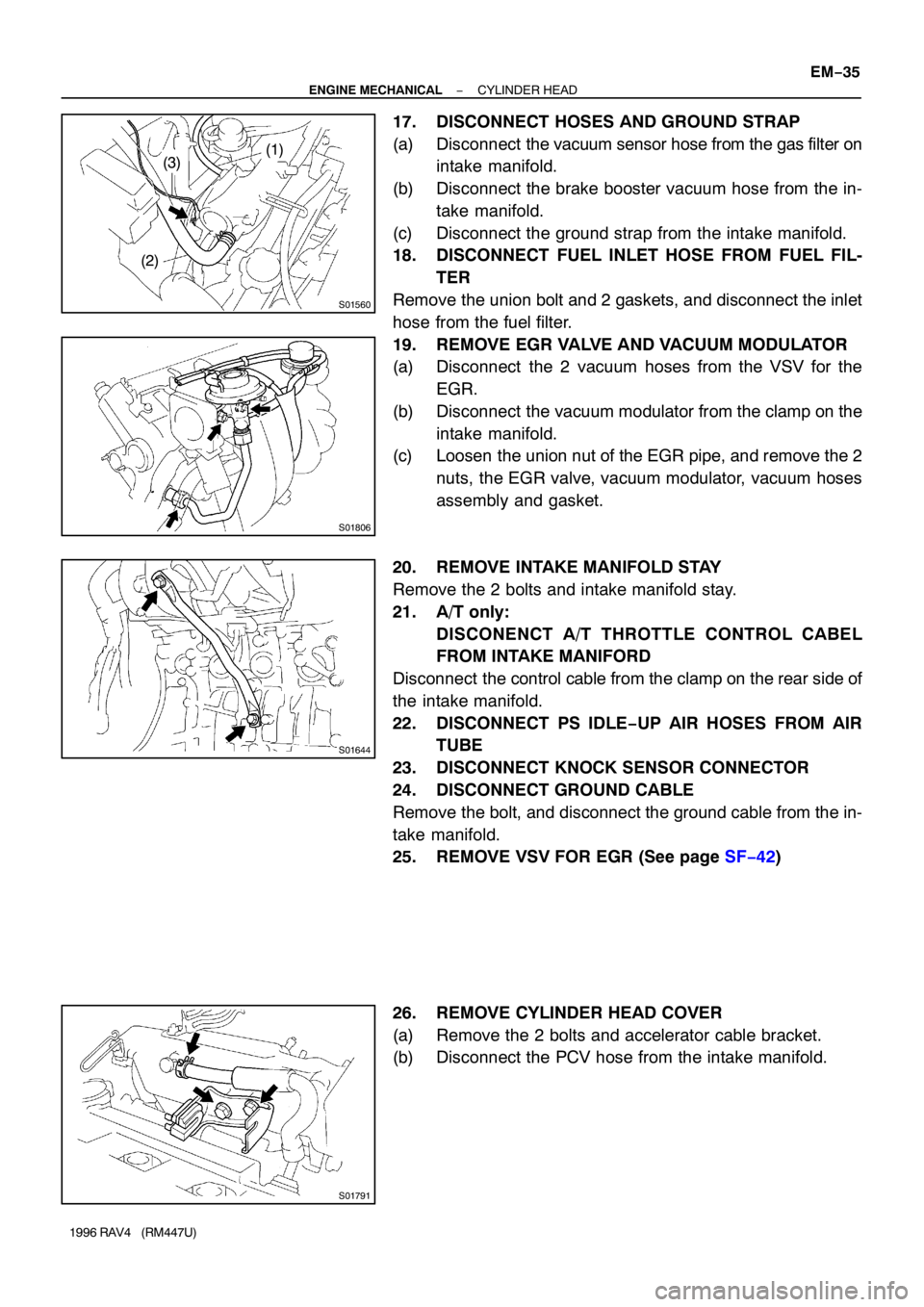
17. DISCONNECT HOSES AND GROUND STRAP
(a) Disconnect the vacuum sensor hose from the gas filter on
intake manifold.
(b) Disconnect the brake booster vacuum hose from the in-
take manifold.
(c) Disconnect the ground strap from the intake manifold.
18. DISCONNECT FUEL INLET HOSE FROM FUEL FIL-
TER
Remove the union bolt and 2 gaskets, and disconnect the inlet
hose from the fuel filter.
19. REMOVE EGR VALVE AND VACUUM MODULATOR
(a) Disconnect the 2 vacuum hoses from the VSV for the
EGR.
(b) Disconnect the vacuum modulator from the clamp on the
intake manifold.
(c) Loosen the union nut of the EGR pipe, and remove the 2
nuts, the EGR valve, vacuum modulator, vacuum hoses
assembly and gasket.
20. REMOVE INTAKE MANIFOLD STAY
Remove the 2 bolts and intake manifold stay.
21. A/T only:
DISCONENCT A/T THROTTLE CONTROL CABEL
FROM INTAKE MANIFORD
Disconnect the control cable from the clamp on the rear side of
the intake manifold.
22. DISCONNECT PS IDLE−UP AIR HOSES FROM AIR
TUBE
23. DISCONNECT KNOCK SENSOR CONNECTOR
24. DISCONNECT GROUND CABLE
Remove the bolt, and disconnect the ground cable from the in-
take manifold.
25. REMOVE VSV FOR EGR (See page SF−42)
26. REMOVE CYLINDER HEAD COVER
(a) Remove the 2 bolts and accelerator cable bracket.
(b) Disconnect the PCV hose from the intake manifold.
Page 702 of 1354
S01653
1 2
S01646
S01647
S01645
S01432
EM−36
− ENGINE MECHANICALCYLINDER HEAD
1996 RAV4 (RM447U)
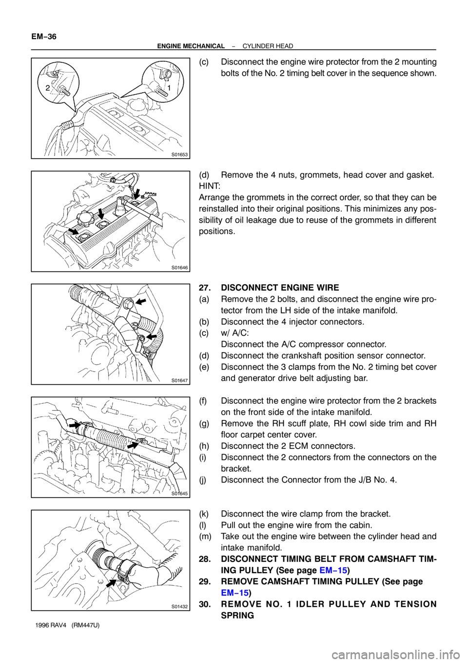
(c) Disconnect the engine wire protector from the 2 mounting
bolts of the No. 2 timing belt cover in the sequence shown.
(d) Remove the 4 nuts, grommets, head cover and gasket.
HINT:
Arrange the grommets in the correct order, so that they can be
reinstalled into their original positions. This minimizes any pos-
sibility of oil leakage due to reuse of the grommets in different
positions.
27. DISCONNECT ENGINE WIRE
(a) Remove the 2 bolts, and disconnect the engine wire pro-
tector from the LH side of the intake manifold.
(b) Disconnect the 4 injector connectors.
(c) w/ A/C:
Disconnect the A/C compressor connector.
(d) Disconnect the crankshaft position sensor connector.
(e) Disconnect the 3 clamps from the No. 2 timing bet cover
and generator drive belt adjusting bar.
(f) Disconnect the engine wire protector from the 2 brackets
on the front side of the intake manifold.
(g) Remove the RH scuff plate, RH cowl side trim and RH
floor carpet center cover.
(h) Disconnect the 2 ECM connectors.
(i) Disconnect the 2 connectors from the connectors on the
bracket.
(j) Disconnect the Connector from the J/B No. 4.
(k) Disconnect the wire clamp from the bracket.
(l) Pull out the engine wire from the cabin.
(m) Take out the engine wire between the cylinder head and
intake manifold.
28. DISCONNECT TIMING BELT FROM CAMSHAFT TIM-
ING PULLEY (See page EM−15)
29. REMOVE CAMSHAFT TIMING PULLEY (See page
EM−15)
30. REMOVE NO. 1 IDLER PULLEY AND TENSION
SPRING
Page 725 of 1354
S01805
S01793
9 10
3 45 6
1 2
7 8
EM7797
Seal Packing
S01649
S01645
− ENGINE MECHANICALCYLINDER HEAD
EM−59
1996 RAV4 (RM447U)
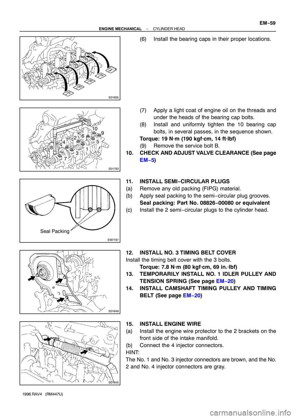
(6) Install the bearing caps in their proper locations.
(7) Apply a light coat of engine oil on the threads and
under the heads of the bearing cap bolts.
(8) Install and uniformly tighten the 10 bearing cap
bolts, in several passes, in the sequence shown.
Torque: 19 N·m (190 kgf·cm, 14 ft·lbf)
(9) Remove the service bolt B.
10. CHECK AND ADJUST VALVE CLEARANCE (See page
EM−5)
11. INSTALL SEMI−CIRCULAR PLUGS
(a) Remove any old packing (FIPG) material.
(b) Apply seal packing to the semi−circular plug grooves.
Seal packing: Part No. 08826−00080 or equivalent
(c) Install the 2 semi−circular plugs to the cylinder head.
12. INSTALL NO. 3 TIMING BELT COVER
Install the timing belt cover with the 3 bolts.
Torque: 7.8 N·m (80 kgf·cm, 69 in.·lbf)
13. TEMPORARILY INSTALL NO. 1 IDLER PULLEY AND
TENSION SPRING (See page EM−20)
14. INSTALL CAMSHAFT TIMING PULLEY AND TIMING
BELT (See page EM−20)
15. INSTALL ENGINE WIRE
(a) Install the engine wire protector to the 2 brackets on the
front side of the intake manifold.
(b) Connect the 4 injector connectors.
HINT:
The No. 1 and No. 3 injector connectors are brown, and the No.
2 and No. 4 injector connectors are gray.
Page 726 of 1354
S01647
S01432
P03283
: Seal Packing
S01658Marking 15°
15°
Z17351
12 EM−60
− ENGINE MECHANICALCYLINDER HEAD
1996 RAV4 (RM447U)
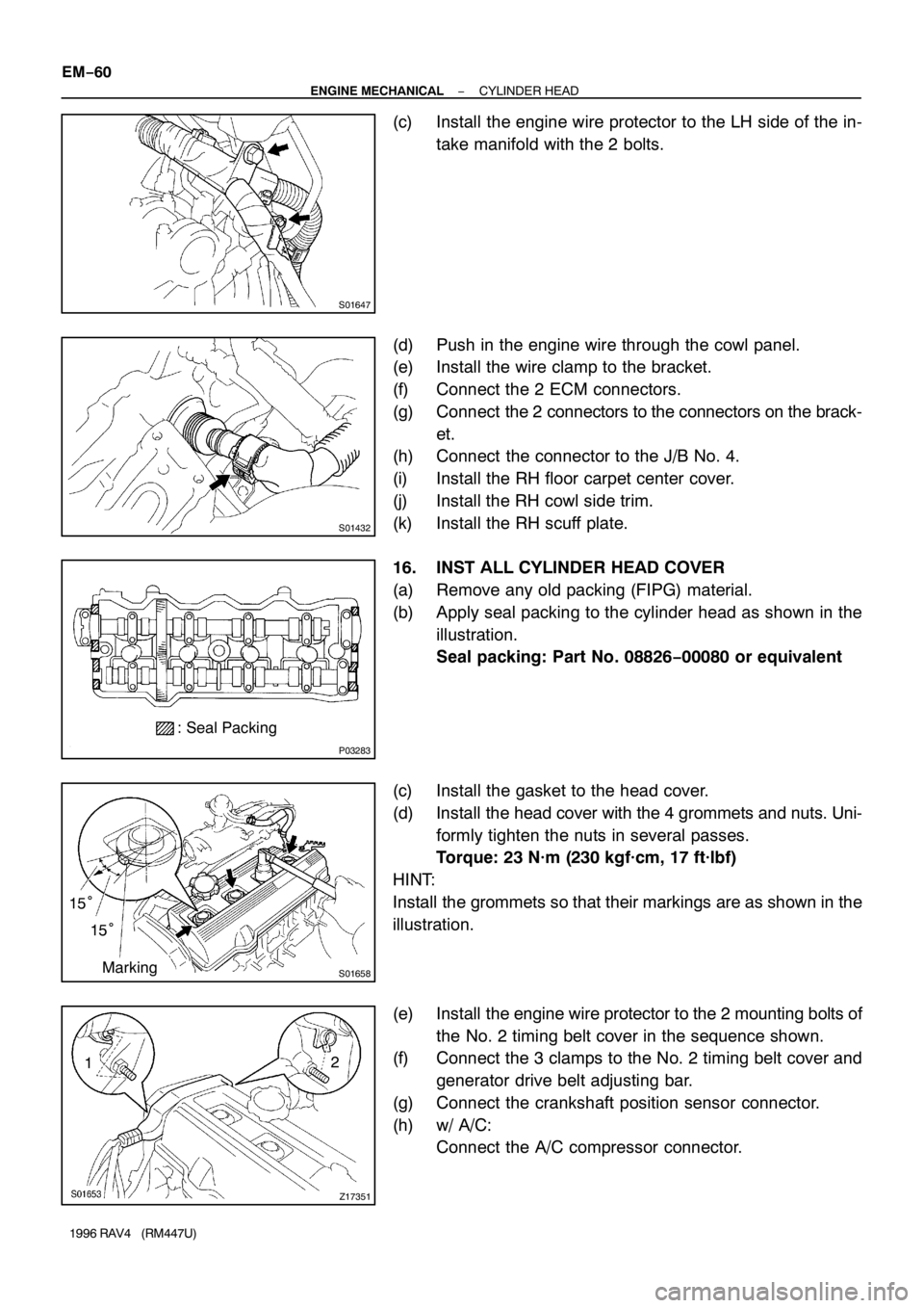
(c) Install the engine wire protector to the LH side of the in-
take manifold with the 2 bolts.
(d) Push in the engine wire through the cowl panel.
(e) Install the wire clamp to the bracket.
(f) Connect the 2 ECM connectors.
(g) Connect the 2 connectors to the connectors on the brack-
et.
(h) Connect the connector to the J/B No. 4.
(i) Install the RH floor carpet center cover.
(j) Install the RH cowl side trim.
(k) Install the RH scuff plate.
16. INST ALL CYLINDER HEAD COVER
(a) Remove any old packing (FIPG) material.
(b) Apply seal packing to the cylinder head as shown in the
illustration.
Seal packing: Part No. 08826−00080 or equivalent
(c) Install the gasket to the head cover.
(d) Install the head cover with the 4 grommets and nuts. Uni-
formly tighten the nuts in several passes.
Torque: 23 N·m (230 kgf·cm, 17 ft·lbf)
HINT:
Install the grommets so that their markings are as shown in the
illustration.
(e) Install the engine wire protector to the 2 mounting bolts of
the No. 2 timing belt cover in the sequence shown.
(f) Connect the 3 clamps to the No. 2 timing belt cover and
generator drive belt adjusting bar.
(g) Connect the crankshaft position sensor connector.
(h) w/ A/C:
Connect the A/C compressor connector.
Page 727 of 1354
S01791
S01644
S01806
− ENGINE MECHANICALCYLINDER HEAD
EM−61
1996 RAV4 (RM447U)
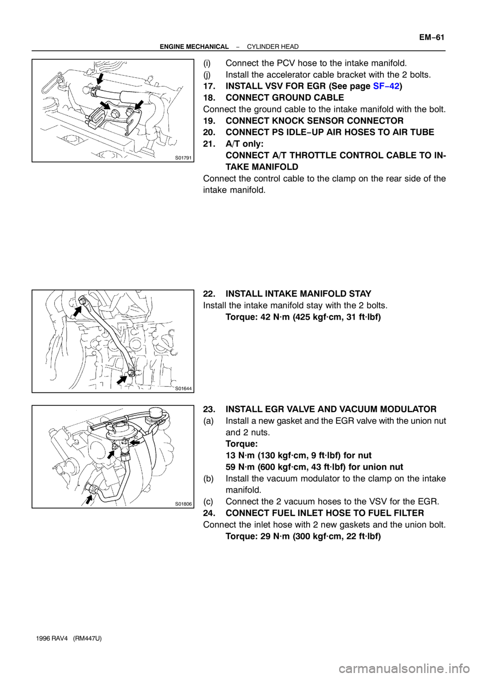
(i) Connect the PCV hose to the intake manifold.
(j) Install the accelerator cable bracket with the 2 bolts.
17. INSTALL VSV FOR EGR (See page SF−42)
18. CONNECT GROUND CABLE
Connect the ground cable to the intake manifold with the bolt.
19. CONNECT KNOCK SENSOR CONNECTOR
20. CONNECT PS IDLE−UP AIR HOSES TO AIR TUBE
21. A/T only:
CONNECT A/T THROTTLE CONTROL CABLE TO IN-
TAKE MANIFOLD
Connect the control cable to the clamp on the rear side of the
intake manifold.
22. INSTALL INTAKE MANIFOLD STAY
Install the intake manifold stay with the 2 bolts.
Torque: 42 N·m (425 kgf·cm, 31 ft·lbf)
23. INSTALL EGR VALVE AND VACUUM MODULATOR
(a) Install a new gasket and the EGR valve with the union nut
and 2 nuts.
Torque:
13 N·m (130 kgf·cm, 9 ft·lbf) for nut
59 N·m (600 kgf·cm, 43 ft·lbf) for union nut
(b) Install the vacuum modulator to the clamp on the intake
manifold.
(c) Connect the 2 vacuum hoses to the VSV for the EGR.
24. CONNECT FUEL INLET HOSE TO FUEL FILTER
Connect the inlet hose with 2 new gaskets and the union bolt.
Torque: 29 N·m (300 kgf·cm, 22 ft·lbf)
Page 798 of 1354

28
G ELECTRICAL WIRING ROUTING
Position of Parts in Engine Compartment
*1 : w/ A/C
*2 : w/o A/C
A 1 A/C Condenser Fan Motor E 1 Electronically Controlled Transmission Solenoid
A 2 A/C Magnetic Clutch and Lock Sensor E 2 Engine Coolant Temp. Sensor
A 3 A/C Triple Pressure SW (A/C Dual and Single
Pressure SW) F 1 Front Side Marker Light LH
A 4 A/C Water Temp. SW F 2 Front Side Marker Light RH
A 5 A/T Fluid Temp. SW F 3 Front Turn Signal Light LH and Front Parking
A 6 ABS Actuator Light LH
A 7 ABS Actuator F 4 Front Turn Signal Light RH and Front Parking
A 8 ABS Relay Light RH
A 9 ABS Relay F 5 Front Washer Motor
A 10 ABS Speed Sensor Front LH F 6 Front Wiper Motor
A 11 ABS Speed Sensor Front RH F 7 Fusible Link Block
B 1 Back-Up Light SW (M/T) G 1 Generator
B 2 Brake Fluid Level Warning SW G 2Generator
C 1 Center Diff. Lock Warning Buzzer SW H 1 Headlight LH
C 2 Crankshaft Position Sensor H 2 Headlight RH
C 3 Cruise Control Actuator H 3 Horn
D 1 Data Link Connector 1
Page 825 of 1354
56
POWER SOURCE
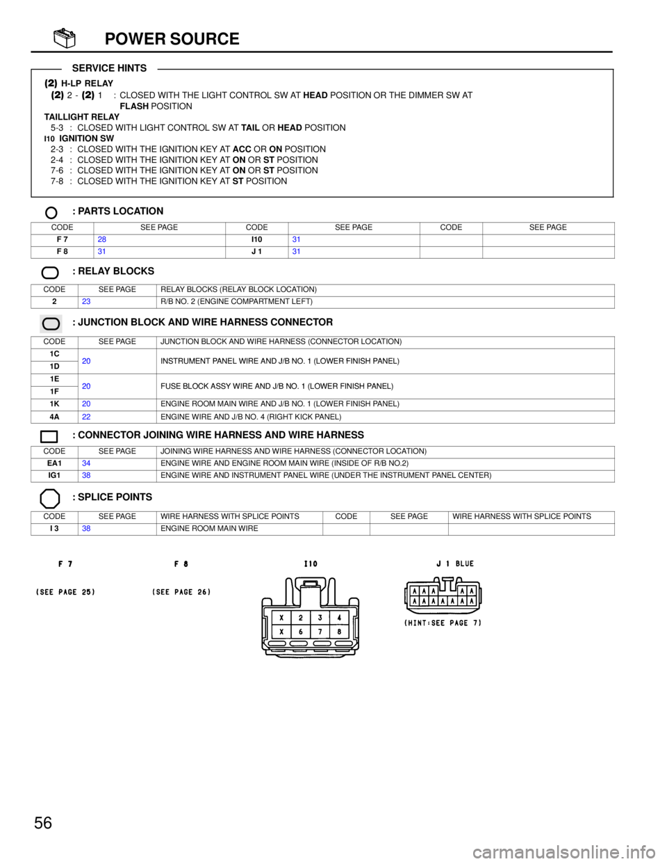
(2) H-LP RELAY
(2) 2 - (2) 1 : CLOSED WITH THE LIGHT CONTROL SW AT HEAD POSITION OR THE DIMMER SW AT
FLASH POSITION
TAILLIGHT RELAY
5-3 : CLOSED WITH LIGHT CONTROL SW AT TAIL OR HEAD POSITION
I10 IGNITION SW
2-3 : CLOSED WITH THE IGNITION KEY AT ACC OR ON POSITION
2-4 : CLOSED WITH THE IGNITION KEY AT ON OR ST POSITION
7-6 : CLOSED WITH THE IGNITION KEY AT ON OR ST POSITION
7-8 : CLOSED WITH THE IGNITION KEY AT ST POSITION
: PARTS LOCATION
CODESEE PAGECODESEE PAGECODESEE PAGE
F 728I1031
F 831J 131
: RELAY BLOCKS
CODESEE PAGERELAY BLOCKS (RELAY BLOCK LOCATION)
223R/B NO. 2 (ENGINE COMPARTMENT LEFT)
: JUNCTION BLOCK AND WIRE HARNESS CONNECTOR
CODESEE PAGEJUNCTION BLOCK AND WIRE HARNESS (CONNECTOR LOCATION)
1C20INSTRUMENT PANEL WIRE AND J/B NO 1 (LOWER FINISH PANEL)1D20INSTRUMENT PANEL WIRE AND J/B NO. 1 (LOWER FINISH PANEL)
1E20FUSE BLOCK ASSY WIRE AND J/B NO 1 (LOWER FINISH PANEL)1F20FUSE BLOCK ASSY WIRE AND J/B NO. 1 (LOWER FINISH PANEL)
1K20ENGINE ROOM MAIN WIRE AND J/B NO. 1 (LOWER FINISH PANEL)
4A22ENGINE WIRE AND J/B NO. 4 (RIGHT KICK PANEL)
: CONNECTOR JOINING WIRE HARNESS AND WIRE HARNESS
CODESEE PAGEJOINING WIRE HARNESS AND WIRE HARNESS (CONNECTOR LOCATION)
EA134ENGINE WIRE AND ENGINE ROOM MAIN WIRE (INSIDE OF R/B NO.2)
IG138ENGINE WIRE AND INSTRUMENT PANEL WIRE (UNDER THE INSTRUMENT PANEL CENTER)
: SPLICE POINTS
CODESEE PAGEWIRE HARNESS WITH SPLICE POINTSCODESEE PAGEWIRE HARNESS WITH SPLICE POINTS
I 338ENGINE ROOM MAIN WIRE
SERVICE HINTS
Page 853 of 1354
![TOYOTA RAV4 1996 Service Repair Manual 84
TAILLIGHT AND ILLUMINATION
IDE 1 E 1B 9
EA BIB 5
17
LIGHT CONTROL SW C13
BATTERY
W
LG W
W-BW-B
W-B
W-B
W-BG
G
G
G
1
TAIL
SE BLOCK]
G G
G FRON IG HT RH F 2
FRON LH F 3
FRON RH F 4
FRON IG HT LH F 1
TOYOTA RAV4 1996 Service Repair Manual 84
TAILLIGHT AND ILLUMINATION
IDE 1 E 1B 9
EA BIB 5
17
LIGHT CONTROL SW C13
BATTERY
W
LG W
W-BW-B
W-B
W-B
W-BG
G
G
G
1
TAIL
SE BLOCK]
G G
G FRON IG HT RH F 2
FRON LH F 3
FRON RH F 4
FRON IG HT LH F 1](/img/14/57462/w960_57462-852.png)
84
TAILLIGHT AND ILLUMINATION
IDE 1 E 1B 9
EA BIB 5
17
LIGHT CONTROL SW C13
BATTERY
W
LG W
W-BW-B
W-B
W-B
W-BG
G
G
G
1
TAIL
SE BLOCK]
G G
G FRON IG HT RH F 2
FRON LH F 3
FRON RH F 4
FRON IG HT LH F 1
REAR GHT RH R11
W-B
G G
G
W-G
I 7G
G
TO DIODE
(
ENGINE IDLE-UP)
GG
TAILL
[REA H ] R 9
W-B G
BJ
LICE N L 1
W-B G
210A
[FU F 8
1J 11L12 1E 31I2
2 2
OFF
TAIL
HEADTEDH 15
[C O M B . S W ]
2 1
2 1
1 2
1 2
1 2
T SIDE MARKER L
T PARKING LIGHT
T PARKING LIGHT
T SIDE MARKER L
SIDE MARKER LI5 1IG HT R H
R COM B. LIGHT R
2 1SE PLATE LIG HT
FUSIBLE LINK
BLOCK F 7
100A A LT
W-B
AAAA
JUNCTION
CONNECTOR J 1 6
A
23 15
1K 11G31F6 TAILLIGHT
RELAY
Page 1233 of 1354
SF0QI−03
S01903
S01939
(1)
(2)
S01827
S01949
Disconnect
Spacer
− SFIINJECTOR
SF−19
1996 RAV4 (RM447U)
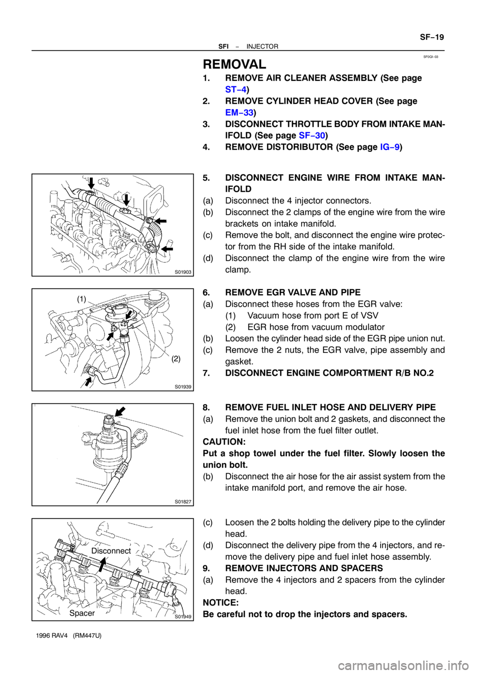
REMOVAL
1. REMOVE AIR CLEANER ASSEMBLY (See page
ST−4)
2. REMOVE CYLINDER HEAD COVER (See page
EM−33)
3. DISCONNECT THROTTLE BODY FROM INTAKE MAN-
IFOLD (See page SF−30)
4. REMOVE DISTORIBUTOR (See page IG−9)
5. DISCONNECT ENGINE WIRE FROM INTAKE MAN-
IFOLD
(a) Disconnect the 4 injector connectors.
(b) Disconnect the 2 clamps of the engine wire from the wire
brackets on intake manifold.
(c) Remove the bolt, and disconnect the engine wire protec-
tor from the RH side of the intake manifold.
(d) Disconnect the clamp of the engine wire from the wire
clamp.
6. REMOVE EGR VALVE AND PIPE
(a) Disconnect these hoses from the EGR valve:
(1) Vacuum hose from port E of VSV
(2) EGR hose from vacuum modulator
(b) Loosen the cylinder head side of the EGR pipe union nut.
(c) Remove the 2 nuts, the EGR valve, pipe assembly and
gasket.
7. DISCONNECT ENGINE COMPORTMENT R/B NO.2
8. REMOVE FUEL INLET HOSE AND DELIVERY PIPE
(a) Remove the union bolt and 2 gaskets, and disconnect the
fuel inlet hose from the fuel filter outlet.
CAUTION:
Put a shop towel under the fuel filter. Slowly loosen the
union bolt.
(b) Disconnect the air hose for the air assist system from the
intake manifold port, and remove the air hose.
(c) Loosen the 2 bolts holding the delivery pipe to the cylinder
head.
(d) Disconnect the delivery pipe from the 4 injectors, and re-
move the delivery pipe and fuel inlet hose assembly.
9. REMOVE INJECTORS AND SPACERS
(a) Remove the 4 injectors and 2 spacers from the cylinder
head.
NOTICE:
Be careful not to drop the injectors and spacers.