symbol TOYOTA RAV4 1996 Service Repair Manual
[x] Cancel search | Manufacturer: TOYOTA, Model Year: 1996, Model line: RAV4, Model: TOYOTA RAV4 1996Pages: 1354, PDF Size: 30.43 MB
Page 209 of 1354
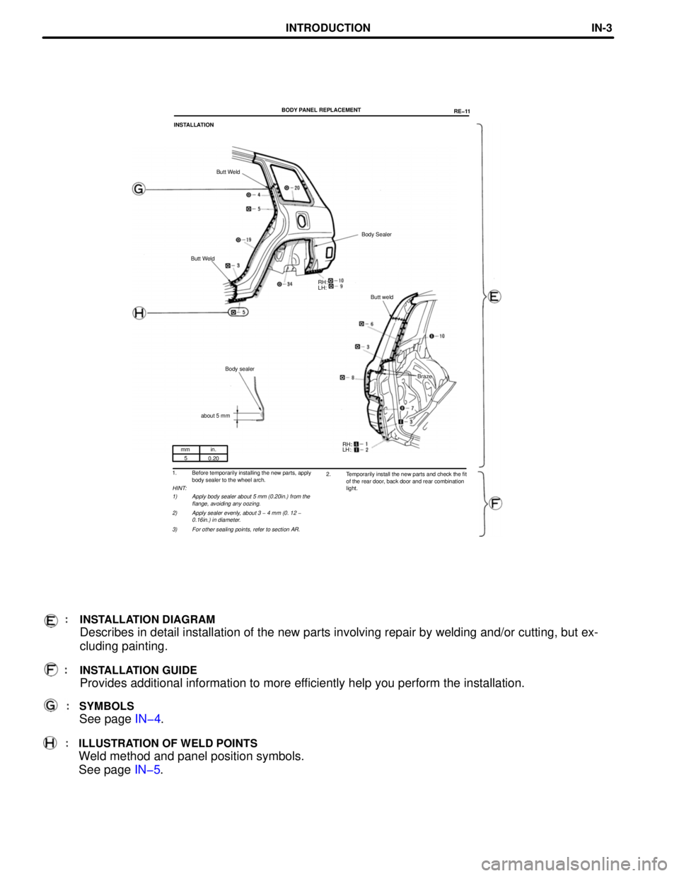
mm in.
5
0.20
1. Before temporarily installing the new parts, apply
body sealer to the wheel arch.
HINT:
1) Apply body sealer about 5 mm (0.20in.) from the
flange, avoiding any oozing.
2) Apply sealer evenly, about 3 - 4 mm (0. 12 -
0.16in.) in diameter.
3) For other sealing points, refer to section AR.
SYMBOLS
See page IN-4.
RH:
LH: BODY PANEL REPLACEMENT
RE-11
INSTALLATION
Butt Weld
Body Sealer
Butt Weld
Butt weld
Body sealer
Braze
about 5 mm
RH:
LH:
2. Temporarily install the new parts and check the fit
of the rear door, back door and rear combination
light.
INSTALLATION DIAGRAM
Describes in detail installation of the new parts involving repair by welding and/or cutting, but exœ
cluding painting.
INSTALLATION GUIDE
Provides additional information to more efficiently help you perform the installation.
ILLUSTRATION OF WELD POINTS
Weld method and panel position symbols.
See page IN-5.
INTRODUCTIONINœ3
Page 210 of 1354
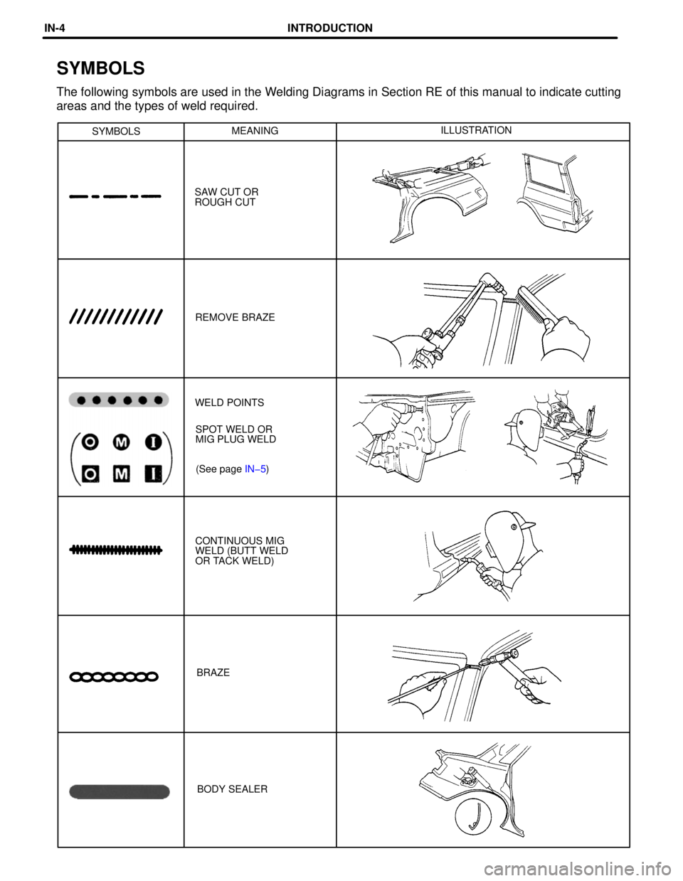
SYMBOLSMEANINGILLUSTRATION
SAW CUT OR
ROUGH CUT
REMOVE BRAZE
(See page IN-5) SPOT WELD OR
MIG PLUG WELD WELD POINTS
BRAZE CONTINUOUS MIG
WELD (BUTT WELD
OR TACK WELD)
BODY SEALER
SYMBOLS
The following symbols are used in the Welding Diagrams in Section RE of this manual to indicate cutting
areas and the types of weld required.
INTRODUCTIONINœ4
Page 211 of 1354
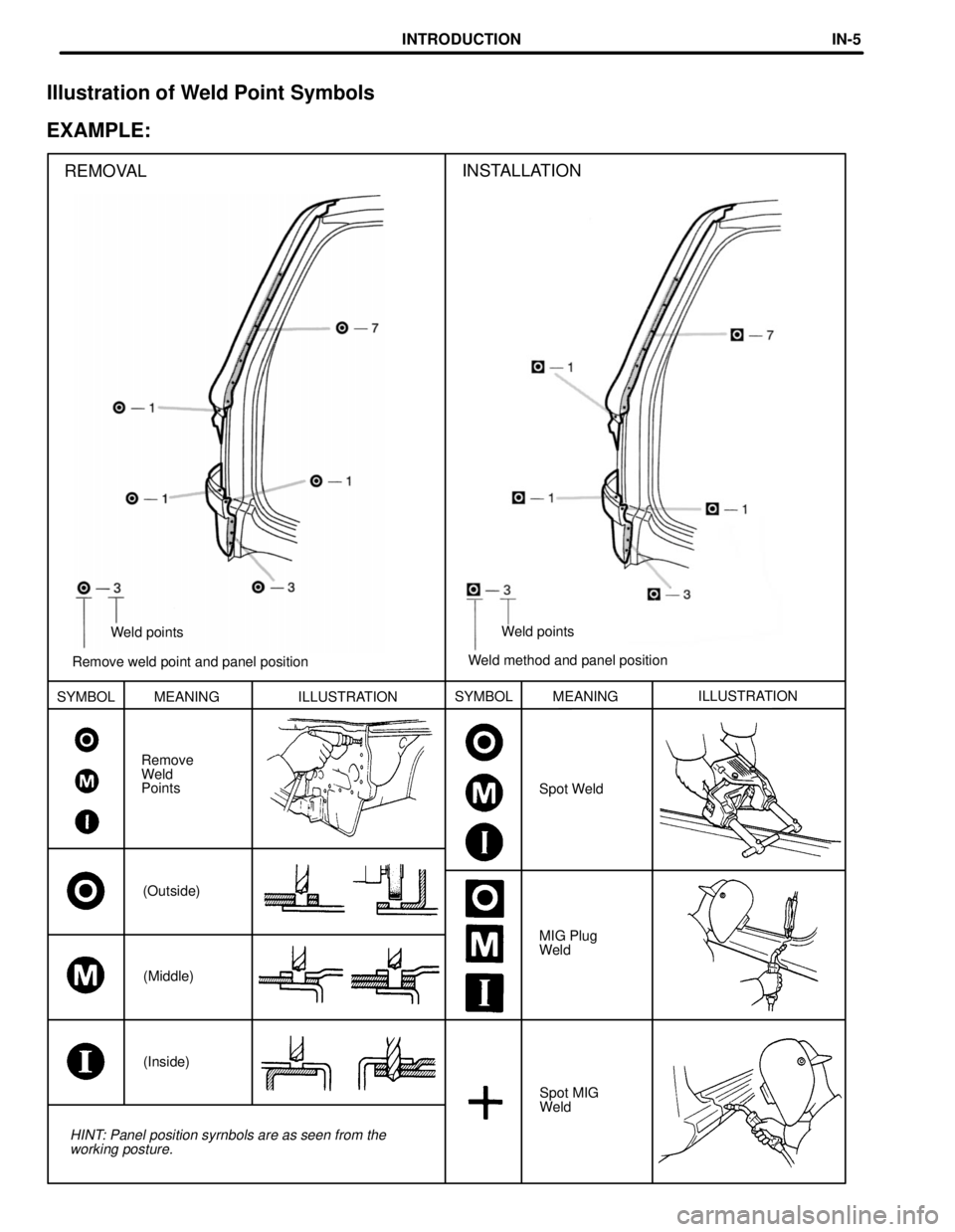
Remove weld point and panel positionWeld points
REMOVAL
Weld method and panel positionWeld points
INSTALLATION
SYMBOL MEANING ILLUSTRATIONSYMBOL
Spot WeldMEANINGILLUSTRATION
Remove
Weld
Points
(Outside)
MIG Plug
Weld
(Middle)
(Inside)
Spot MIG
Weld
HINT: Panel position syrnbols are as seen from the
working posture.
Illustration of Weld Point Symbols
EXAMPLE:
INTRODUCTIONINœ5
Page 216 of 1354
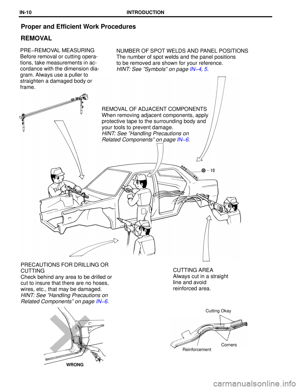
Proper and Efficient Work Procedures
REMOVAL
NUMBER OF SPOT WELDS AND PANEL POSITIONS
The number of spot welds and the panel positions
to be removed are shown for your reference.
HINT: See ºSymbolsº on page IN-4, 5.
PRE-REMOVAL MEASURING
Before removal or cutting operaœ
tions, take measurements in acœ
cordance with the dimension diaœ
gram. Always use a puller to
straighten a damaged body or
frame.
REMOVAL OF ADJACENT COMPONENTS
When removing adjacent components, apply
protective tape to the surrounding body and
your tools to prevent damage.
HINT: See ºHandling Precautions on
Related Componentsº on page IN-6.
CUTTING AREA
Always cut in a straight
line and avoid
reinforced area. PRECAUTIONS FOR DRILLING OR
CUTTING
Check behind any area to be drilled or
cut to insure that there are no hoses,
wires, etc., that may be damaged.
HINT: See ºHandling Precautions on
Related Componentsº on page IN-6.
Cutting Okay
Corners
Reinforcement
WRONG
INTRODUCTIONINœ10
Page 223 of 1354
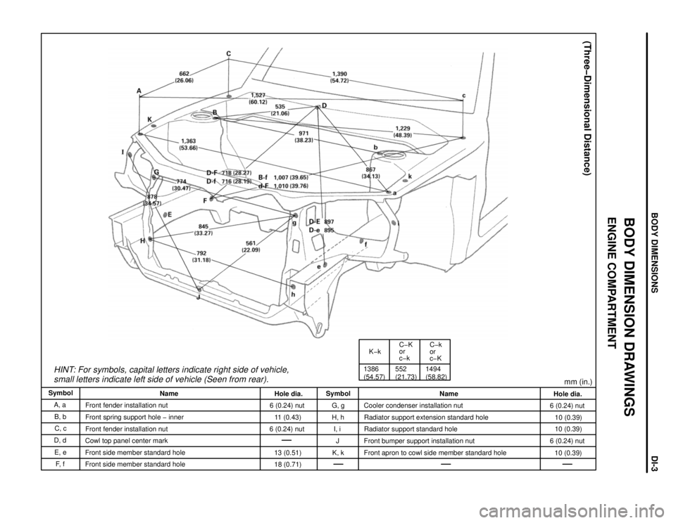
HINT: For symbols, capital letters indicate right side of vehicle,
small letters indicate left side of vehicle (Seen from rear).
K-k
1386
(54.57)552
(21.73)C-K
or
c-k
1494
(58.82)C-k
or
c-K
(Three-Dimensional Distance)
mm (in.)
Hole dia.
6 (0.24) nut
10 (0.39)
10 (0.39)
6 (0.24) nut
10 (0.39) Name
Cooler condenser installation nut
Radiator support extension standard hole
Radiator support standard hole
Front bumper support installation nut
Front apron to cowl side member standard hole Symbol
G, g
H, h
I, i
J
K, k Hole dia.
6 (0.24) nut
11 (0.43)
6 (0.24) nut
13 (0.51)
18 (0.71) Name
Front fender installation nut
Front spring support hole - inner
Front fender installation nut
Cowl top panel center mark
Front side member standard hole
Front side member standard hole Symbol
A, a
B, b
C, c
D, d
E, e
F, f
BODY DIMENSION DRAWINGS
ENGINE COMPARTMENT
BODY DIMENSIONSDIœ3
Page 224 of 1354
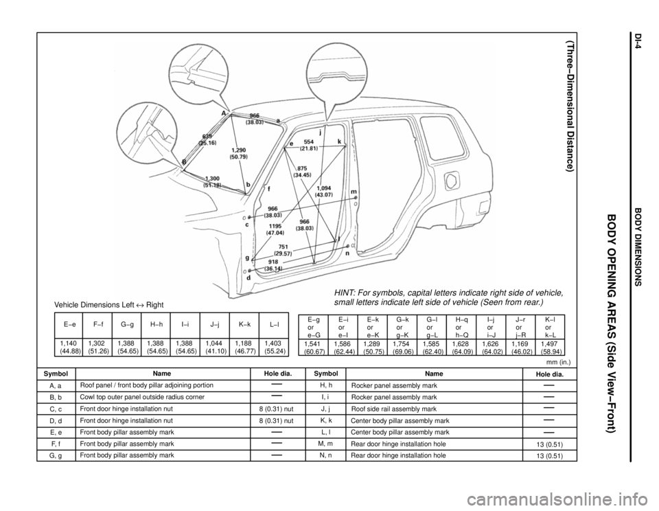
1,140
(44.88)E-e
1,302
(51.26)F-fVehicle Dimensions Left e Right
1,388
(54.65)G-g H-h
1,388
(54.65)I-i
1,388
(54.65)1,044
(41.10)J-j
1,188
(46.77)K-k
1,403
(55.24)L-l
1,541
(60.67)E-g
or
e-G
1,586
(62.44)E-i
or
e-IE-k
or
e-K
1,289
(50.75)1,754
(69.06)G-k
or
g-K
1,585
(62.40)G-l
or
g-LH-q
or
h-Q
1,628
(64.09)I-j
or
i-J
1,626
(64.02)J-r
or
j-R
1,169
(46.02)1,497
(58.94)
HINT: For symbols, capital letters indicate right side of vehicle,
small letters indicate left side of vehicle (Seen from rear.)
K-l
or
k-L
(Three-Dimensional Distance)
mm (in.)
Hole dia.
13 (0.51)
13 (0.51) Name
Rocker panel assembly mark
Rocker panel assembly mark
Roof side rail assembly mark
Center body pillar assembly mark
Center body pillar assembly mark
Rear door hinge installation hole
Rear door hinge installation hole Symbol
H, h
I, i
J, j
K, k
L, l
M, m
N, n Hole dia.
8 (0.31) nut
8 (0.31) nut Name
Roof panel / front body pillar adjoining portion
Cowl top outer panel outside radius corner
Front door hinge installation nut
Front door hinge installation nut
Front body pillar assembly mark
Front body pillar assembly mark
Front body pillar assembly mark Symbol
A, a
B, b
C, c
D, d
E, e
F, f
G, g
BODY OPENING AREAS (Side View-Front)
BODY DIMENSIONSDIœ4
Page 225 of 1354
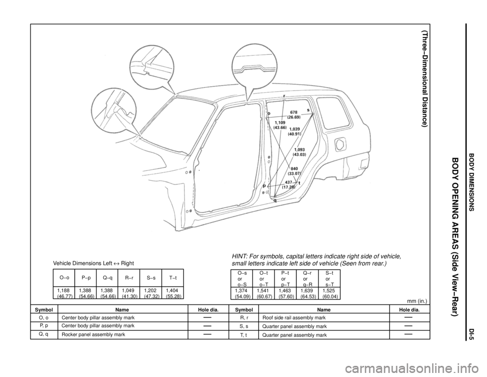
Vehicle Dimensions Left e Right
O-o
1,188
(46.77)P-p
1,388
(54.66)1,388
(54.66)Q-q
R-r
1,049
(41.30)S-s
1,202
(47.32)1,404
(55.28)T-t
1,374
(54.09)O-s
or
o-SO-t
or
o-T
1,541
(60.67)1,463
(57.60)P-t
or
p-T
1,639
(64.53)Q-r
or
q-R
1,525
(60.04)S-t
or
s-T
HINT: For symbols, capital letters indicate right side of vehicle,
small letters indicate left side of vehicle (Seen from rear.)
mm (in.)
(Three-Dimensional Distance)
Hole dia. Name
Roof side rail assembly mark
Quarter panel assembly mark
Quarter panel assembly mark Symbol
R, r
S, s
T, t Hole dia. Name
Center body pillar assembly mark
Center body pillar assembly mark
Rocker panel assembly mark Symbol
O, o
P, p
Q, q
BODY OPENING AREAS (Side View-Rear)
BODY DIMENSIONSDIœ5
Page 226 of 1354
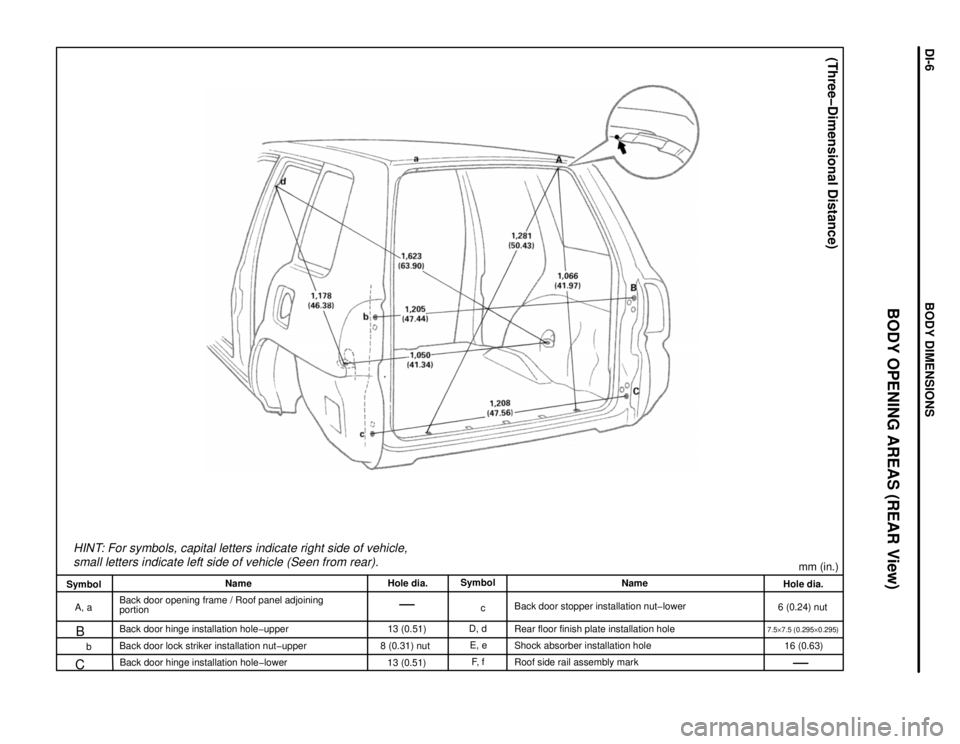
HINT: For symbols, capital letters indicate right side of vehicle,
small letters indicate left side of vehicle (Seen from rear).
mm (in.)
(Three-Dimensional Distance)
Hole dia.
6 (0.24) nut
7.5y7.5 (0.295y0.295)
16 (0.63) Name
Back door stopper installation nut-lower
Rear floor finish plate installation hole
Shock absorber installation hole
Roof side rail assembly mark Symbol
c
D, d
E, e
F, f Hole dia.
13 (0.51)
8 (0.31) nut
13 (0.51) Name
Back door opening frame / Roof panel adjoining
portion
Back door hinge installation hole-upper
B
Back door lock striker installation nut-upper
C
Back door hinge installation hole-lower Symbol
A, a
b
BODY OPENING AREAS (REAR View)
BODY DIMENSIONSDIœ6
Page 227 of 1354
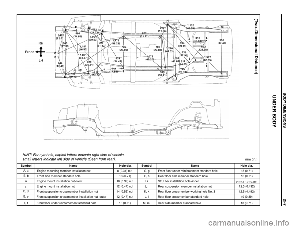
HINT: For symbols, capital letters indicate right side of vehicle,
small letters indicate left side of vehicle (Seen from rear).
(Two-Dimensional Distance)
mm (in.)
Hole dia.
18 (0.71)
18 (0.71)
34y17.5 (1.34y0.689)12.5 (0.492)
12.5 (4.492)
10 (0.39)
18 (0.71) Name
Front floor under reinforcement standard hole
Rear floor side member standard hole
Strut bar installation hole-inner
Rear suspension member installation nut
Rear floor crossmember working hole No. 3
Rear floor crossmember standard hole
Rear side member standard hole Symbol
G, g
H, h
I, i
J, j
K, k
L, l
M, m Hole dia.
8 (0.31) nut
18 (0.71)
10 (0.39) nut
12 (0.47) nut
14 (0.55) nut
12 (0.47) nut
18 (0.71) Name
Engine mounting member installation nut
Front side member standard hole
Engine mount installation nut-front
Engine mount installation nut
Front suspension crossmember installation nut
Front suspension crossmember installation nut-outer
Front floor under reinforcement standard hole Symbol
A, a
B, b
C
c
D, d
E, e
F, f
UNDER BODY
BODY DIMENSIONSDIœ7
Page 228 of 1354
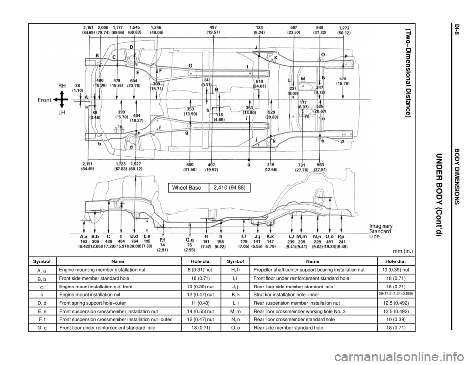
Wheel Base2,410 (94.88)
Imaginary
Standard
Line
mm (in.)
(Two-Dimensional Distance)
Hole dia.
10 (0.39) nut
18 (0.71)
18 (0.71)
39y17.5 (1.34y0.689)12.5 (0.492)
12.5 (0.492)
10 (0.39)
18 (0.71) Name
Propeller shaft center support bearing installation nut
Front floor under reinforcement standard hole
Rear floor side member standard hole
Strut bar installation hole-inner
Rear suspension member installation nut
Rear floor crossmember working hole No. 3
Rear floor crossmember standard hole
Rear side member standard hole Symbol
H, h
I, i
J, j
K, k
L, l
M, rn
N, n
O, o Hole dia.
8 (0.31) nut
18 (0.71)
10 (0.39) nut
12 (0.47) nut
11 (0.43)
14 (0.55) nut
12 (0.47) nut
18 (0.71) Name
Engine mounting member installation nut
Front side member standard hole
Engine mount installation nut-front
Engine mount installation nut
Front spring support hole-outer
Front suspension crossmember installation nut
Front suspension crossmember installation nut-outer
Front floor under reinforcement standard hole Symbol
A, a
B, b
C
c
D, d
E, e
F, f
UNDER BODY (Cont'd)
G, g
BODY DIMENSIONSDIœ8