Trim TOYOTA RAV4 2006 Service Repair Manual
[x] Cancel search | Manufacturer: TOYOTA, Model Year: 2006, Model line: RAV4, Model: TOYOTA RAV4 2006Pages: 2000, PDF Size: 45.84 MB
Page 457 of 2000
DL–108DOOR LOCK – DOOR CONTROL RECEIVER
DL
INSTALLATION
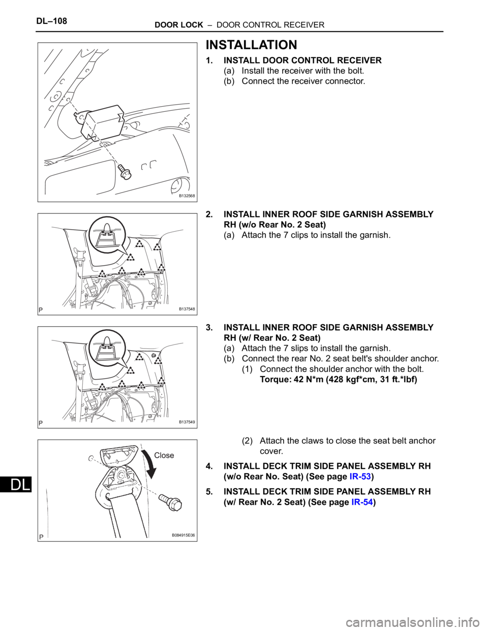
1. INSTALL DOOR CONTROL RECEIVER
(a) Install the receiver with the bolt.
(b) Connect the receiver connector.
2. INSTALL INNER ROOF SIDE GARNISH ASSEMBLY
RH (w/o Rear No. 2 Seat)
(a) Attach the 7 clips to install the garnish.
3. INSTALL INNER ROOF SIDE GARNISH ASSEMBLY
RH (w/ Rear No. 2 Seat)
(a) Attach the 7 slips to install the garnish.
(b) Connect the rear No. 2 seat belt's shoulder anchor.
(1) Connect the shoulder anchor with the bolt.
Torque: 42 N*m (428 kgf*cm, 31 ft.*lbf)
(2) Attach the claws to close the seat belt anchor
cover.
4. INSTALL DECK TRIM SIDE PANEL ASSEMBLY RH
(w/o Rear No. Seat) (See page IR-53)
5. INSTALL DECK TRIM SIDE PANEL ASSEMBLY RH
(w/ Rear No. 2 Seat) (See page IR-54)
B132568
B137548
B137549
B084915E06
Page 458 of 2000
DOOR LOCK – DOOR CONTROL RECEIVERDL–109
DL
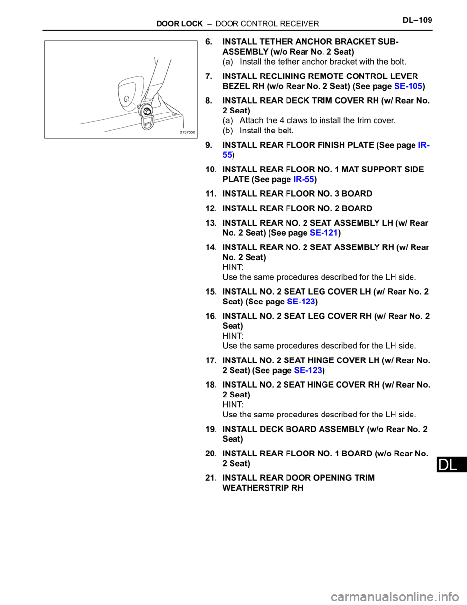
6. INSTALL TETHER ANCHOR BRACKET SUB-
ASSEMBLY (w/o Rear No. 2 Seat)
(a) Install the tether anchor bracket with the bolt.
7. INSTALL RECLINING REMOTE CONTROL LEVER
BEZEL RH (w/o Rear No. 2 Seat) (See page SE-105)
8. INSTALL REAR DECK TRIM COVER RH (w/ Rear No.
2 Seat)
(a) Attach the 4 claws to install the trim cover.
(b) Install the belt.
9. INSTALL REAR FLOOR FINISH PLATE (See page IR-
55)
10. INSTALL REAR FLOOR NO. 1 MAT SUPPORT SIDE
PLATE (See page IR-55)
11. INSTALL REAR FLOOR NO. 3 BOARD
12. INSTALL REAR FLOOR NO. 2 BOARD
13. INSTALL REAR NO. 2 SEAT ASSEMBLY LH (w/ Rear
No. 2 Seat) (See page SE-121)
14. INSTALL REAR NO. 2 SEAT ASSEMBLY RH (w/ Rear
No. 2 Seat)
HINT:
Use the same procedures described for the LH side.
15. INSTALL NO. 2 SEAT LEG COVER LH (w/ Rear No. 2
Seat) (See page SE-123)
16. INSTALL NO. 2 SEAT LEG COVER RH (w/ Rear No. 2
Seat)
HINT:
Use the same procedures described for the LH side.
17. INSTALL NO. 2 SEAT HINGE COVER LH (w/ Rear No.
2 Seat) (See page SE-123)
18. INSTALL NO. 2 SEAT HINGE COVER RH (w/ Rear No.
2 Seat)
HINT:
Use the same procedures described for the LH side.
19. INSTALL DECK BOARD ASSEMBLY (w/o Rear No. 2
Seat)
20. INSTALL REAR FLOOR NO. 1 BOARD (w/o Rear No.
2 Seat)
21. INSTALL REAR DOOR OPENING TRIM
WEATHERSTRIP RH
B137550
Page 493 of 2000
2AZ-FE ENGINE CONTROL SYSTEM – SFI SYSTEMES–39
ES
3. 2 TRIP DETECTION LOGIC
When a malfunction is first detected, the malfunction is
temporarily stored in the ECM memory (1st trip). If the
same malfunction is detected during the next
subsequent drive cycle, the MIL is illuminated (2nd trip).
4. FREEZE FRAME DATA
Freeze frame data records the engine conditions (fuel
system, calculated engine load, engine coolant
temperature, fuel trim, engine speed, vehicle speed,
etc.) when malfunctions are detected. When
troubleshooting, freeze frame data can help determine if
the vehicle was moving or stationary, if the engine was
warmed up or not, if the air-fuel ratio was lean or rich,
and other data from the time the malfunction occurred.
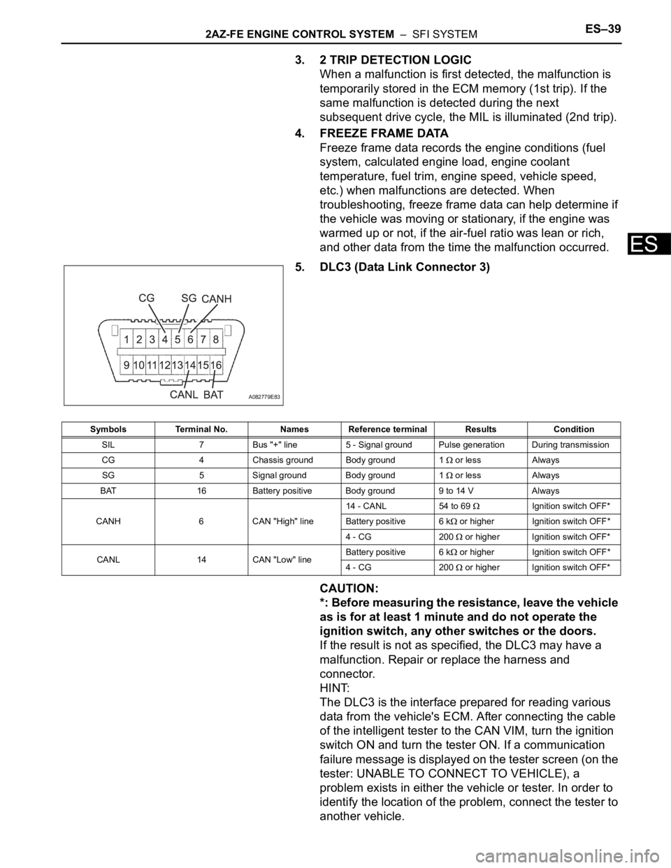
5. DLC3 (Data Link Connector 3)
CAUTION:
*: Before measuring the resistance, leave the vehicle
as is for at least 1 minute and do not operate the
ignition switch, any other switches or the doors.
If the result is not as specified, the DLC3 may have a
malfunction. Repair or replace the harness and
connector.
HINT:
The DLC3 is the interface prepared for reading various
data from the vehicle's ECM. After connecting the cable
of the intelligent tester to the CAN VIM, turn the ignition
switch ON and turn the tester ON. If a communication
failure message is displayed on the tester screen (on the
tester: UNABLE TO CONNECT TO VEHICLE), a
problem exists in either the vehicle or tester. In order to
identify the location of the problem, connect the tester to
another vehicle.
A082779E83
Symbols Terminal No. Names Reference terminal Results Condition
SIL 7 Bus "+" line 5 - Signal ground Pulse generation During transmission
CG 4 Chassis ground Body ground 1
or less Always
SG 5 Signal ground Body ground 1
or less Always
BAT 16 Battery positive Body ground 9 to 14 V Always
CANH 6 CAN "High" line14 - CANL 54 to 69
Ignition switch OFF*
Battery positive 6 k
or higher Ignition switch OFF*
4 - CG 200
or higher Ignition switch OFF*
CANL 14 CAN "Low" lineBattery positive 6 k
or higher Ignition switch OFF*
4 - CG 200
or higher Ignition switch OFF*
Page 496 of 2000
ES–422AZ-FE ENGINE CONTROL SYSTEM – SFI SYSTEM
ES
FREEZE FRAME DATA
1. DESCRIPTION
Freeze frame data records the engine conditions (fuel
system, calculated load, engine coolant temperature,
fuel trim, engine speed, vehicle speed, etc.) when a
malfunction is detected. When troubleshooting, it can
help determine if the vehicle was running or stopped, the
engine was warmed up or not, the air-fuel ratio was Lean
or Rich, and other data from the time the malfunction
occurred.
HINT:
If it is impossible to duplicate the problem even though a
DTC is detected, confirm the freeze frame data.
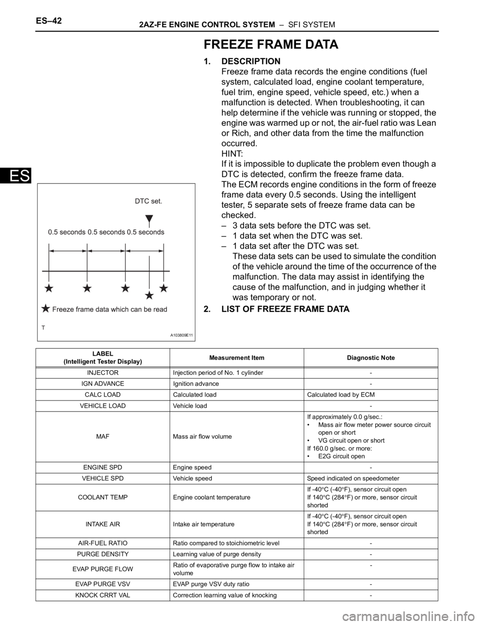
The ECM records engine conditions in the form of freeze
frame data every 0.5 seconds. Using the intelligent
tester, 5 separate sets of freeze frame data can be
checked.
– 3 data sets before the DTC was set.
– 1 data set when the DTC was set.
– 1 data set after the DTC was set.
These data sets can be used to simulate the condition
of the vehicle around the time of the occurrence of the
malfunction. The data may assist in identifying the
cause of the malfunction, and in judging whether it
was temporary or not.
2. LIST OF FREEZE FRAME DATA
A103809E11
LABEL
(Intelligent Tester Display)Measurement Item Diagnostic Note
INJECTOR Injection period of No. 1 cylinder -
IGN ADVANCE Ignition advance -
CALC LOAD Calculated load Calculated load by ECM
VEHICLE LOAD Vehicle load -
MAF Mass air flow volumeIf approximately 0.0 g/sec.:
• Mass air flow meter power source circuit
open or short
• VG circuit open or short
If 160.0 g/sec. or more:
• E2G circuit open
ENGINE SPD Engine speed -
VEHICLE SPD Vehicle speed Speed indicated on speedometer
COOLANT TEMP Engine coolant temperatureIf -40
C (-40F), sensor circuit open
If 140
C (284F) or more, sensor circuit
shorted
INTAKE AIR Intake air temperature If -40
C (-40F), sensor circuit open
If 140
C (284F) or more, sensor circuit
shorted
AIR-FUEL RATIO Ratio compared to stoichiometric level -
PURGE DENSITY Learning value of purge density -
EVAP PURGE FLOWRatio of evaporative purge flow to intake air
volume-
EVAP PURGE VSV EVAP purge VSV duty ratio -
KNOCK CRRT VAL Correction learning value of knocking -
Page 497 of 2000
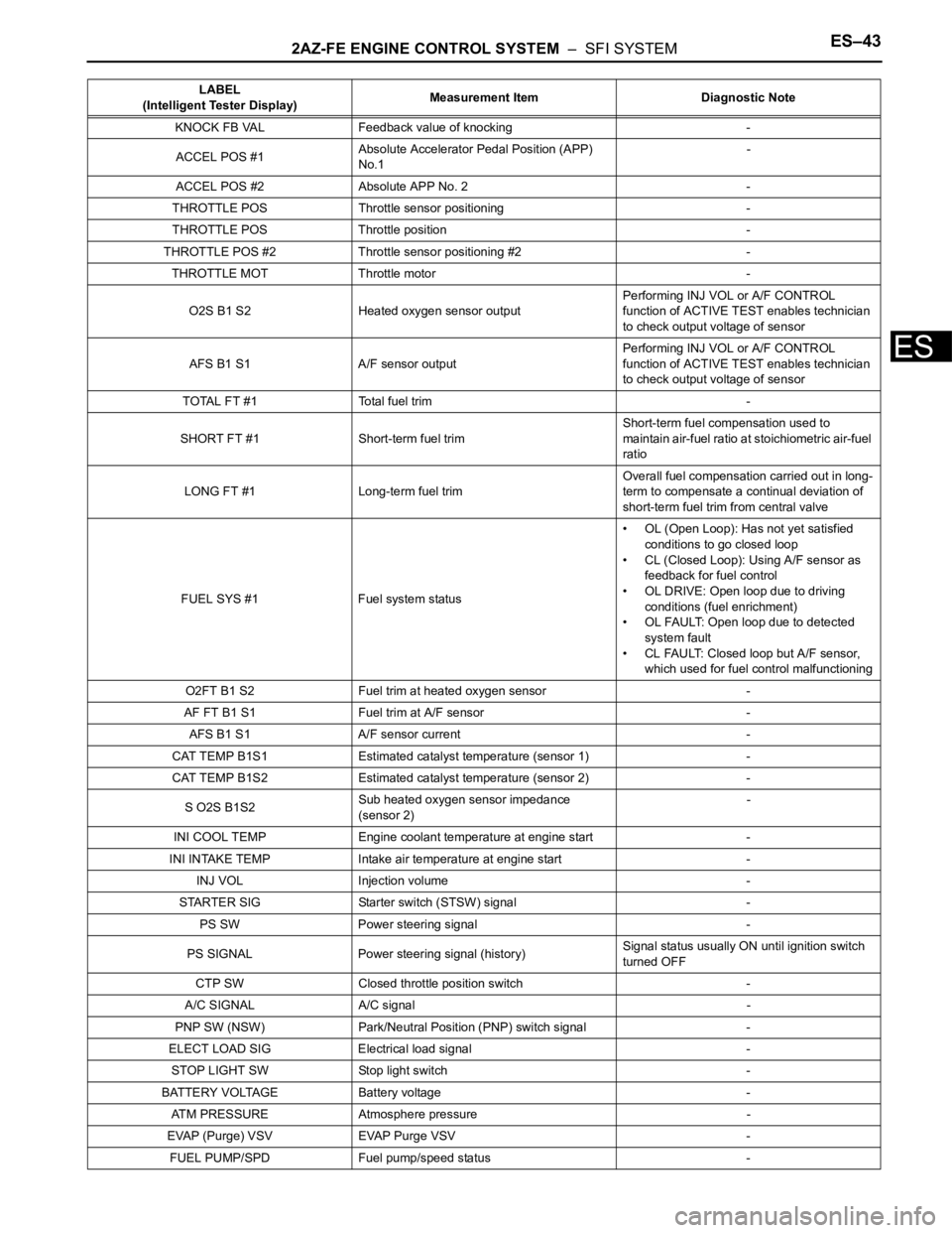
2AZ-FE ENGINE CONTROL SYSTEM – SFI SYSTEMES–43
ES
KNOCK FB VAL Feedback value of knocking -
ACCEL POS #1Absolute Accelerator Pedal Position (APP)
No.1-
ACCEL POS #2 Absolute APP No. 2 -
THROTTLE POS Throttle sensor positioning -
THROTTLE POS Throttle position -
THROTTLE POS #2 Throttle sensor positioning #2 -
THROTTLE MOT Throttle motor -
O2S B1 S2 Heated oxygen sensor outputPerforming INJ VOL or A/F CONTROL
function of ACTIVE TEST enables technician
to check output voltage of sensor
AFS B1 S1 A/F sensor outputPerforming INJ VOL or A/F CONTROL
function of ACTIVE TEST enables technician
to check output voltage of sensor
TOTAL FT #1 Total fuel trim -
SHORT FT #1 Short-term fuel trimShort-term fuel compensation used to
maintain air-fuel ratio at stoichiometric air-fuel
ratio
LONG FT #1 Long-term fuel trimOverall fuel compensation carried out in long-
term to compensate a continual deviation of
short-term fuel trim from central valve
FUEL SYS #1 Fuel system status• OL (Open Loop): Has not yet satisfied
conditions to go closed loop
• CL (Closed Loop): Using A/F sensor as
feedback for fuel control
• OL DRIVE: Open loop due to driving
conditions (fuel enrichment)
• OL FAULT: Open loop due to detected
system fault
• CL FAULT: Closed loop but A/F sensor,
which used for fuel control malfunctioning
O2FT B1 S2 Fuel trim at heated oxygen sensor -
AF FT B1 S1 Fuel trim at A/F sensor -
AFS B1 S1 A/F sensor current -
CAT TEMP B1S1 Estimated catalyst temperature (sensor 1) -
CAT TEMP B1S2 Estimated catalyst temperature (sensor 2) -
S O2S B1S2Sub heated oxygen sensor impedance
(sensor 2)-
INI COOL TEMP Engine coolant temperature at engine start -
INI INTAKE TEMP Intake air temperature at engine start -
INJ VOL Injection volume -
STARTER SIG Starter switch (STSW) signal -
PS SW Power steering signal -
PS SIGNAL Power steering signal (history)Signal status usually ON until ignition switch
turned OFF
CTP SW Closed throttle position switch -
A/C SIGNAL A/C signal -
PNP SW (NSW) Park/Neutral Position (PNP) switch signal -
ELECT LOAD SIG Electrical load signal -
STOP LIGHT SW Stop light switch -
BATTERY VOLTAGE Battery voltage -
ATM PRESSURE Atmosphere pressure -
EVAP (Purge) VSV EVAP Purge VSV -
FUEL PUMP/SPD Fuel pump/speed status -LABEL
(Intelligent Tester Display)Measurement Item Diagnostic Note
Page 567 of 2000
2GR-FE ENGINE CONTROL SYSTEM – SFI SYSTEMES–43
ES
3. 2 TRIP DETECTION LOGIC
When a malfunction is first detected, the malfunction is
temporarily stored in the ECM memory (1st trip). If the
same malfunction is detected during the next
subsequent drive cycle, the MIL is illuminated (2nd trip).
4. FREEZE FRAME DATA
Freeze frame data records the engine conditions (fuel
system, calculated engine load, engine coolant
temperature, fuel trim, engine speed, vehicle speed,
etc.) when malfunctions are detected. When
troubleshooting, freeze frame data can help determine if
the vehicle was moving or stationary, if the engine was
warmed up or not, if the air-fuel ratio was lean or rich,
and other data from the time the malfunction occurred.
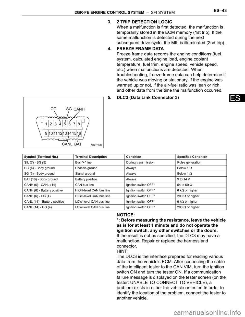
5. DLC3 (Data Link Connector 3)
NOTICE:
*: Before measuring the resistance, leave the vehicle
as is for at least 1 minute and do not operate the
ignition switch, any other switches or the doors.
If the result is not as specified, the DLC3 may have a
malfunction. Repair or replace the harness and
connector.
HINT:
The DLC3 is the interface prepared for reading various
data from the vehicle's ECM. After connecting the cable
of the intelligent tester to the CAN VIM, turn the ignition
switch ON and turn the tester ON. If a communication
failure message is displayed on the tester screen (on the
tester: UNABLE TO CONNECT TO VEHICLE), a
problem exists in either the vehicle or tester. In order to
identify the location of the problem, connect the tester to
another vehicle.
A082779E83
Symbol (Terminal No.) Terminal Description Condition Specified Condition
SIL (7) - SG (5) Bus "+" line During transmission Pulse generation
CG (4) - Body ground Chassis ground Always Below 1
SG (5) - Body ground Signal ground Always Below 1
BAT (16) - Body ground Battery positive Always 9 to 14 V
CANH (6) - CANL (14) CAN bus line Ignition switch OFF* 54 to 69
CANH (6) - Battery positive HIGH-level CAN bus line Ignition switch OFF* 6 k or higher
CANH (6) - CG (4) HIGH-level CAN bus line Ignition switch OFF* 200
or higher
CANL (14) - Battery positive LOW-level CAN bus line Ignition switch OFF* 6 k
or higher
CANL (14) - CG (4) LOW-level CAN bus line Ignition switch OFF* 200
or higher
Page 570 of 2000
ES–462GR-FE ENGINE CONTROL SYSTEM – SFI SYSTEM
ES
FREEZE FRAME DATA
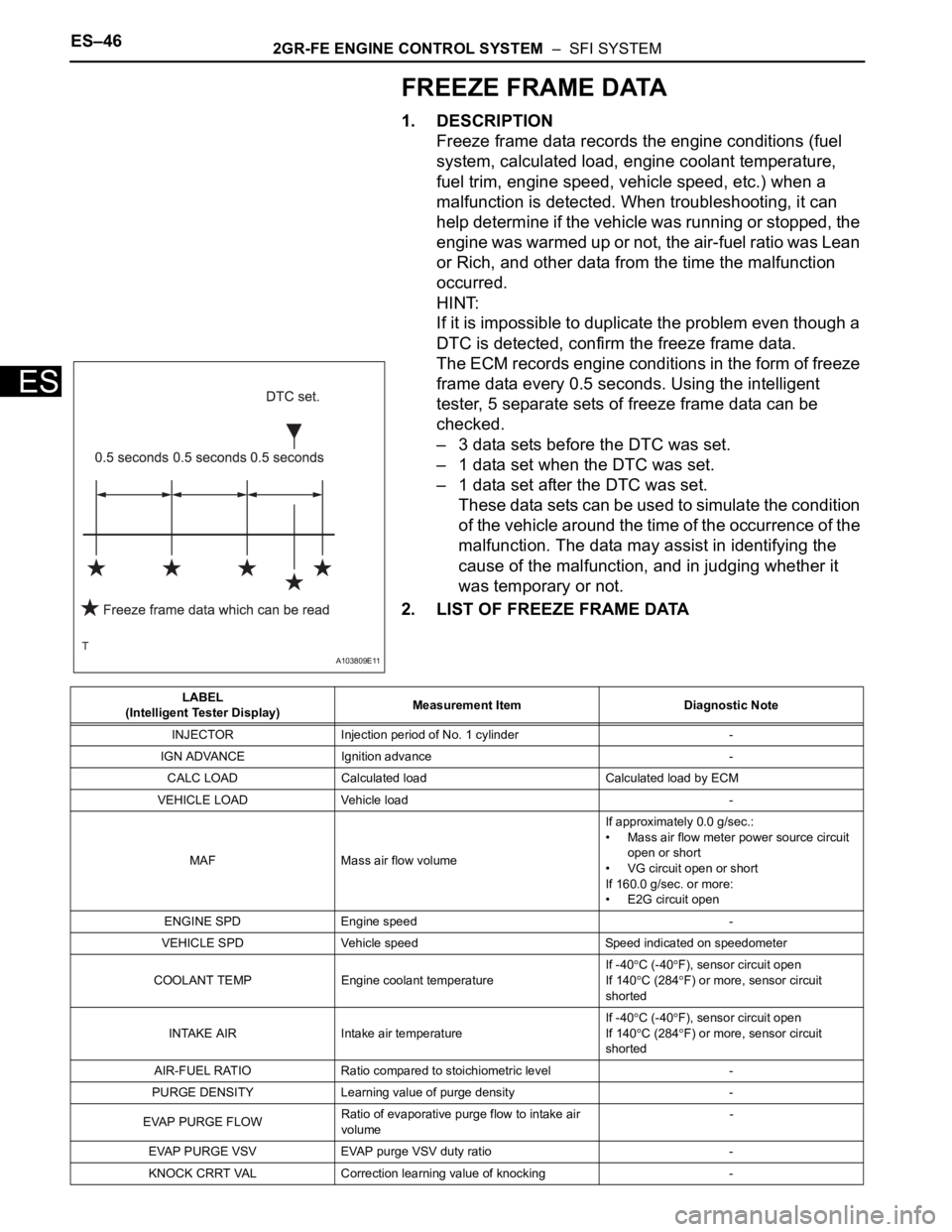
1. DESCRIPTION
Freeze frame data records the engine conditions (fuel
system, calculated load, engine coolant temperature,
fuel trim, engine speed, vehicle speed, etc.) when a
malfunction is detected. When troubleshooting, it can
help determine if the vehicle was running or stopped, the
engine was warmed up or not, the air-fuel ratio was Lean
or Rich, and other data from the time the malfunction
occurred.
HINT:
If it is impossible to duplicate the problem even though a
DTC is detected, confirm the freeze frame data.
The ECM records engine conditions in the form of freeze
frame data every 0.5 seconds. Using the intelligent
tester, 5 separate sets of freeze frame data can be
checked.
– 3 data sets before the DTC was set.
– 1 data set when the DTC was set.
– 1 data set after the DTC was set.
These data sets can be used to simulate the condition
of the vehicle around the time of the occurrence of the
malfunction. The data may assist in identifying the
cause of the malfunction, and in judging whether it
was temporary or not.
2. LIST OF FREEZE FRAME DATA
A103809E11
LABEL
(Intelligent Tester Display)Measurement Item Diagnostic Note
INJECTOR Injection period of No. 1 cylinder -
IGN ADVANCE Ignition advance -
CALC LOAD Calculated load Calculated load by ECM
VEHICLE LOAD Vehicle load -
MAF Mass air flow volumeIf approximately 0.0 g/sec.:
• Mass air flow meter power source circuit
open or short
• VG circuit open or short
If 160.0 g/sec. or more:
• E2G circuit open
ENGINE SPD Engine speed -
VEHICLE SPD Vehicle speed Speed indicated on speedometer
COOLANT TEMP Engine coolant temperatureIf -40
C (-40F), sensor circuit open
If 140
C (284F) or more, sensor circuit
shorted
INTAKE AIR Intake air temperature If -40
C (-40F), sensor circuit open
If 140
C (284F) or more, sensor circuit
shorted
AIR-FUEL RATIO Ratio compared to stoichiometric level -
PURGE DENSITY Learning value of purge density -
EVAP PURGE FLOWRatio of evaporative purge flow to intake air
volume-
EVAP PURGE VSV EVAP purge VSV duty ratio -
KNOCK CRRT VAL Correction learning value of knocking -
Page 571 of 2000
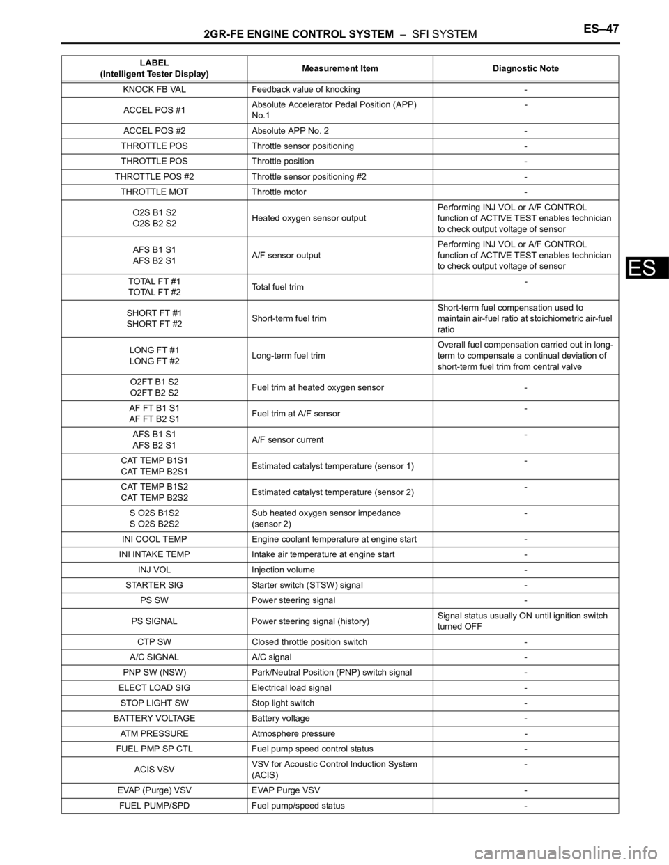
2GR-FE ENGINE CONTROL SYSTEM – SFI SYSTEMES–47
ES
KNOCK FB VAL Feedback value of knocking -
ACCEL POS #1Absolute Accelerator Pedal Position (APP)
No.1-
ACCEL POS #2 Absolute APP No. 2 -
THROTTLE POS Throttle sensor positioning -
THROTTLE POS Throttle position -
THROTTLE POS #2 Throttle sensor positioning #2 -
THROTTLE MOT Throttle motor -
O2S B1 S2
O2S B2 S2Heated oxygen sensor outputPerforming INJ VOL or A/F CONTROL
function of ACTIVE TEST enables technician
to check output voltage of sensor
AFS B1 S1
AFS B2 S1A/F sensor outputPerforming INJ VOL or A/F CONTROL
function of ACTIVE TEST enables technician
to check output voltage of sensor
TOTAL FT #1
TOTAL FT #2Total fuel trim -
SHORT FT #1
SHORT FT #2Short-term fuel trimShort-term fuel compensation used to
maintain air-fuel ratio at stoichiometric air-fuel
ratio
LONG FT #1
LONG FT #2Long-term fuel trimOverall fuel compensation carried out in long-
term to compensate a continual deviation of
short-term fuel trim from central valve
O2FT B1 S2
O2FT B2 S2Fuel trim at heated oxygen sensor -
AF FT B1 S1
AF FT B2 S1Fuel trim at A/F sensor-
AFS B1 S1
AFS B2 S1A/F sensor current-
CAT TEMP B1S1
CAT TEMP B2S1Estimated catalyst temperature (sensor 1)-
CAT TEMP B1S2
CAT TEMP B2S2Estimated catalyst temperature (sensor 2)-
S O2S B1S2
S O2S B2S2Sub heated oxygen sensor impedance
(sensor 2)-
INI COOL TEMP Engine coolant temperature at engine start -
INI INTAKE TEMP Intake air temperature at engine start -
INJ VOL Injection volume -
STARTER SIG Starter switch (STSW) signal -
PS SW Power steering signal -
PS SIGNAL Power steering signal (history)Signal status usually ON until ignition switch
turned OFF
CTP SW Closed throttle position switch -
A/C SIGNAL A/C signal -
PNP SW (NSW) Park/Neutral Position (PNP) switch signal -
ELECT LOAD SIG Electrical load signal -
STOP LIGHT SW Stop light switch -
BATTERY VOLTAGE Battery voltage -
ATM PRESSURE Atmosphere pressure -
FUEL PMP SP CTL Fuel pump speed control status -
ACIS VSVVSV for Acoustic Control Induction System
(ACIS)-
EVAP (Purge) VSV EVAP Purge VSV -
FUEL PUMP/SPD Fuel pump/speed status -LABEL
(Intelligent Tester Display)Measurement Item Diagnostic Note
Page 968 of 2000
AX–34U140F AUTOMATIC TRANSAXLE – AUTOMATIC TRANSAXLE SYSTEM
AX
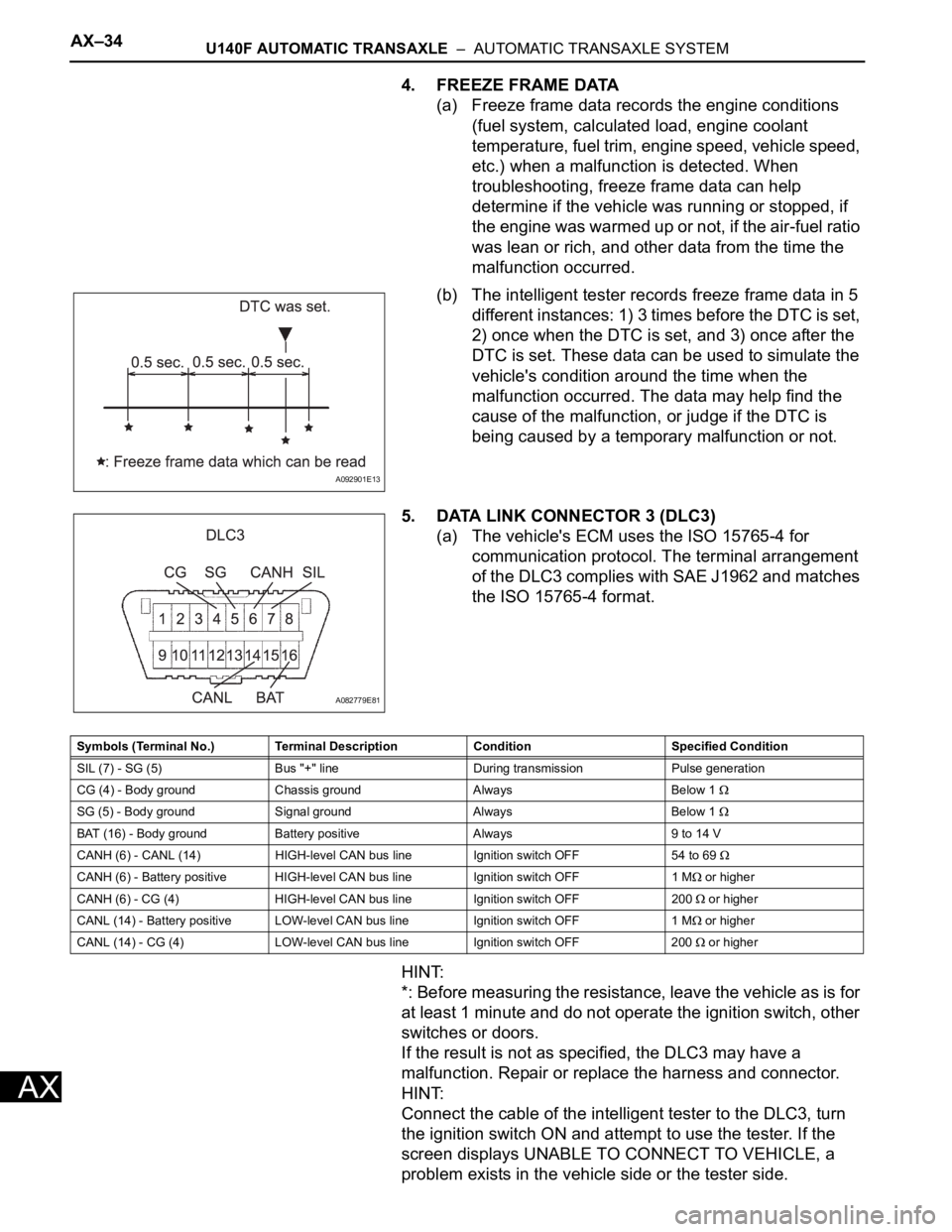
4. FREEZE FRAME DATA
(a) Freeze frame data records the engine conditions
(fuel system, calculated load, engine coolant
temperature, fuel trim, engine speed, vehicle speed,
etc.) when a malfunction is detected. When
troubleshooting, freeze frame data can help
determine if the vehicle was running or stopped, if
the engine was warmed up or not, if the air-fuel ratio
was lean or rich, and other data from the time the
malfunction occurred.
(b) The intelligent tester records freeze frame data in 5
different instances: 1) 3 times before the DTC is set,
2) once when the DTC is set, and 3) once after the
DTC is set. These data can be used to simulate the
vehicle's condition around the time when the
malfunction occurred. The data may help find the
cause of the malfunction, or judge if the DTC is
being caused by a temporary malfunction or not.
5. DATA LINK CONNECTOR 3 (DLC3)
(a) The vehicle's ECM uses the ISO 15765-4 for
communication protocol. The terminal arrangement
of the DLC3 complies with SAE J1962 and matches
the ISO 15765-4 format.
HINT:
*: Before measuring the resistance, leave the vehicle as is for
at least 1 minute and do not operate the ignition switch, other
switches or doors.
If the result is not as specified, the DLC3 may have a
malfunction. Repair or replace the harness and connector.
HINT:
Connect the cable of the intelligent tester to the DLC3, turn
the ignition switch ON and attempt to use the tester. If the
screen displays UNABLE TO CONNECT TO VEHICLE, a
problem exists in the vehicle side or the tester side.
A092901E13
A082779E81
Symbols (Terminal No.) Terminal Description Condition Specified Condition
SIL (7) - SG (5) Bus "+" line During transmission Pulse generation
CG (4) - Body ground Chassis ground Always Below 1
SG (5) - Body ground Signal ground Always Below 1
BAT (16) - Body ground Battery positive Always 9 to 14 V
CANH (6) - CANL (14) HIGH-level CAN bus line Ignition switch OFF 54 to 69
CANH (6) - Battery positive HIGH-level CAN bus line Ignition switch OFF 1 M or higher
CANH (6) - CG (4) HIGH-level CAN bus line Ignition switch OFF 200
or higher
CANL (14) - Battery positive LOW-level CAN bus line Ignition switch OFF 1 M
or higher
CANL (14) - CG (4) LOW-level CAN bus line Ignition switch OFF 200
or higher
Page 1051 of 2000
U151E AUTOMATIC TRANSAXLE – AUTOMATIC TRANSAXLE SYSTEMAX–35
AX
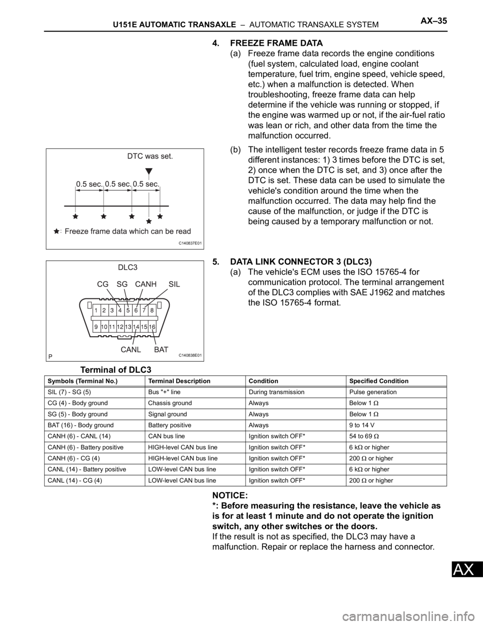
4. FREEZE FRAME DATA
(a) Freeze frame data records the engine conditions
(fuel system, calculated load, engine coolant
temperature, fuel trim, engine speed, vehicle speed,
etc.) when a malfunction is detected. When
troubleshooting, freeze frame data can help
determine if the vehicle was running or stopped, if
the engine was warmed up or not, if the air-fuel ratio
was lean or rich, and other data from the time the
malfunction occurred.
(b) The intelligent tester records freeze frame data in 5
different instances: 1) 3 times before the DTC is set,
2) once when the DTC is set, and 3) once after the
DTC is set. These data can be used to simulate the
vehicle's condition around the time when the
malfunction occurred. The data may help find the
cause of the malfunction, or judge if the DTC is
being caused by a temporary malfunction or not.
5. DATA LINK CONNECTOR 3 (DLC3)
(a) The vehicle's ECM uses the ISO 15765-4 for
communication protocol. The terminal arrangement
of the DLC3 complies with SAE J1962 and matches
the ISO 15765-4 format.
Terminal of DLC3
NOTICE:
*: Before measuring the resistance, leave the vehicle as
is for at least 1 minute and do not operate the ignition
switch, any other switches or the doors.
If the result is not as specified, the DLC3 may have a
malfunction. Repair or replace the harness and connector.
C140837E01
C140838E01
Symbols (Terminal No.) Terminal Description Condition Specified Condition
SIL (7) - SG (5) Bus "+" line During transmission Pulse generation
CG (4) - Body ground Chassis ground Always Below 1
SG (5) - Body ground Signal ground Always Below 1
BAT (16) - Body ground Battery positive Always 9 to 14 V
CANH (6) - CANL (14) CAN bus line Ignition switch OFF* 54 to 69
CANH (6) - Battery positive HIGH-level CAN bus line Ignition switch OFF* 6 k or higher
CANH (6) - CG (4) HIGH-level CAN bus line Ignition switch OFF* 200
or higher
CANL (14) - Battery positive LOW-level CAN bus line Ignition switch OFF* 6 k
or higher
CANL (14) - CG (4) LOW-level CAN bus line Ignition switch OFF* 200
or higher