transfer case TOYOTA RAV4 2006 Service Repair Manual
[x] Cancel search | Manufacturer: TOYOTA, Model Year: 2006, Model line: RAV4, Model: TOYOTA RAV4 2006Pages: 2000, PDF Size: 45.84 MB
Page 388 of 2000

SERVICE SPECIFICATIONS – U140F AUTOMATIC TRANSAXLESS–59
SS
TORQUE SPECIFICATIONS
Automatic Transaxle Assembly
Automatic Transaxle Unit
Part Tightened N*m kgf*cm ft.*lbf
Park/neutral position switch Nut 6.9 70 61 in.*lbf
Bolt 5.4 55 48 in.*lbf
Control shaft lever x Control shaft 12.7 130 9
Shift control cable x Control shaft lever 15 153 11
Transaxle housing x Engine block A bolt 64 653 47
B bolt 46 470 34
Lower side bolt 37 377 27
Torque converter clutch x Drive plate 41 418 30
Engine mounting bracket FR x Transaxle 64 653 47
Oil filler tube x Transaxle 5.5 56 49 in.*lbf
Control cable bracket No.1 x Transaxle 12 122 9
Oil cooler tube clamp x Control cable bracket 5.4 55 48 in.*lbf
Oil cooler inlet tube x Transaxle 34 347 25
Oil cooler outlet tube x Transaxle 34 347 25
Starter x Transaxle37 377 27
Wire harness x Transaxle 13 133 10
Speed sensor (NC) x Transaxle 11 115 8
Speed sensor (NT) x Transaxle 11 112 8
Air cleaner x No. 1 air cleaner inlet 5.0 51 44 in.*lbf
Drain plug x Oil pan47 479 35
Transmission wire x Transaxle 5.4 55 48 in.*lbf
ATF temperature sensor x Valve body 6.6 67 58 in.*lbf
Oil pan x Transaxle7.6 77 67 in.*lbf
Solenoid valve x Valve body Bolt A 6.6 67 58 in.*lbf
Bolt B 11 110 8
Valve body x Transaxle 10.8 110 8
Oil strainer x Valve body 11 110 8
Floor shift assembly x Body 12 120 9
Control cable x Body5.0 51 44 in.*lbf
Transfer x Transaxle69 704 51
Engine mount bracket RR x Transfer stiffener, plate RH 45 459 34
Part Tightened N*m kgf*cm ft.*lbf
Differential gear lube apply tube x Transaxle housing 9.8 100 7
Front planetary gear lock nut 268 2,732 198
Brake apply tube clamp x Transaxle case 5.4 55 48 in.*lbf
Transaxle case No. 1 plug x Transaxle rear cover 7.4 75 65 in.*lbf
Transaxle rear cover plate x transaxle rear cover sub-assembly 7.5 76 66 in.*lbf
Transaxle rear cover x Transaxle case Bolt A 18.6 190 14
Other bolt 24.5 250 18
Pawl shaft clamp x Transaxle case 9.8 100 7
Oil pump assembly x Transaxle case 22 226 16
Transaxle housing x Transaxle case Bolt A 22.1 225 16.3
Bolt B, C 29.4 300 21.7
Transaxle case No. 1 plug x Transaxle housing 7.4 75 65 in.*lbf
Parking lock pawl bracket x Transaxle case 20 205 15
Page 390 of 2000

SS–64SERVICE SPECIFICATIONS – U241E AUTOMATIC TRANSAXLE
SS
TORQUE SPECIFICATIONS
Automatic Transaxle Assembly
Automatic Transaxle Unit
Part Tightened N*m kgf*cm ft.*lbf
Park/neutral position switch Nut 6.9 70 61 in.*lbf
Bolt 5.4 55 48 in.*lbf
Control shaft lever x Control shaft 12.7 130 9
Shift control cable x Control shaft lever 15 153 11
Transaxle housing x Engine block A bolt 64 653 47
B bolt 46 470 34
Lower side bolt 37 377 27
Torque converter clutch x Drive plate 41 418 30
Engine mounting bracket FR x Transaxle 64 653 47
Oil filler tube x Transaxle 5.5 56 49 in.*lbf
Control cable bracket No.1 x Transaxle 12 122 9
Oil cooler tube clamp x Control cable bracket 5.4 55 48 in.*lbf
Oil cooler inlet tube x Transaxle 34 347 25
Oil cooler outlet tube x Transaxle 34 347 25
Starter x Transaxle37 377 27
Wire harness x Transaxle 13 133 10
Speed sensor (NC) x Transaxle 11 115 8
Speed sensor (NT) x Transaxle 11 112 8
Air cleaner x No. 1 air cleaner inlet 5.0 51 44 in.*lbf
Drain plug x Oil pan47 479 35
Transmission wire x Transaxle 5.4 55 48 in.*lbf
ATF temperature sensor x Valve body 6.6 67 58 in.*lbf
Oil pan x Transaxle7.6 77 67 in.*lbf
Solenoid valve x Valve body Bolt A 6.6 67 58 in.*lbf
B o l t B 11 11 0 8
Valve body x Transaxle 10.8 110 8
Oil strainer x Valve body 11 110 8
Floor shift assembly x Body 12 120 9
Control cable x Body5.0 51 44 in.*lbf
Engine mount bracket RR x Transfer stiffener, plate RH 45 459 34
Part Tightened N*m kgf*cm ft.*lbf
Differential gear lube apply tube x Transaxle housing 9.8 100 7
Front planetary gear lock nut 268 2,732 198
Brake apply tube clamp x Transaxle case 5.4 55 48 in.*lbf
Transaxle case No. 1 plug x Transaxle rear cover 7.4 75 65 in.*lbf
Transaxle rear cover plate x transaxle rear cover sub-assembly 7.5 76 66 in.*lbf
Transaxle rear cover x Transaxle case Bolt A 18.6 190 14
Other bolt 24.5 250 18
Pawl shaft clamp x Transaxle case 9.8 100 7
Oil pump assembly x Transaxle case 22 226 16
Transaxle housing x Transaxle case Bolt A 22.1 225 16.3
Bolt B, C 29.4 300 21.7
Transaxle case No. 1 plug x Transaxle housing 7.4 75 65 in.*lbf
Parking lock pawl bracket x Transaxle case 20 205 15
Detent spring x Transaxle case Bolt A 20 205 15
Bolt B 12 120 9
Page 392 of 2000

SERVICE SPECIFICATIONS – GF1A TRANSFERSS–69
SS
TORQUE SPECIFICATIONS
Part Tightened N*m kgf*cm ft.*lbf
Breather oil deflector x transfer
case6.5 66 58
Output shaft x Transfer gear nut 360 3700 266
Driven pinion front bearing x
Transfer case38 390 28
No. 1 transfer case cover x
transfer case47 480 35
Transfer drain plug x transfer
case49 500 36
Transfer drain plug x transfer
case49 500 36
Transfer & Transaxle setting stud
bolt x transfer case39 400 29
Transfer assembly x transaxle 69 700 51
4WD Control ECU x Body 4.5 46 40
Page 1080 of 2000

AX–206U151E AUTOMATIC TRANSAXLE – AUTOMATIC TRANSAXLE UNIT
AX
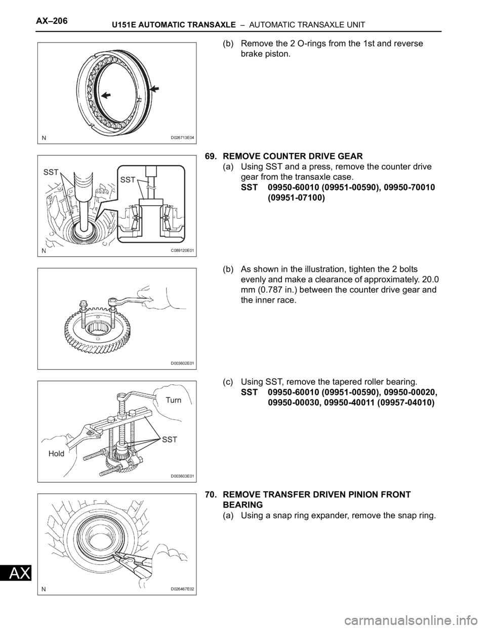
(b) Remove the 2 O-rings from the 1st and reverse
brake piston.
69. REMOVE COUNTER DRIVE GEAR
(a) Using SST and a press, remove the counter drive
gear from the transaxle case.
SST 09950-60010 (09951-00590), 09950-70010
(09951-07100)
(b) As shown in the illustration, tighten the 2 bolts
evenly and make a clearance of approximately. 20.0
mm (0.787 in.) between the counter drive gear and
the inner race.
(c) Using SST, remove the tapered roller bearing.
SST 09950-60010 (09951-00590), 09950-00020,
09950-00030, 09950-40011 (09957-04010)
70. REMOVE TRANSFER DRIVEN PINION FRONT
BEARING
(a) Using a snap ring expander, remove the snap ring.
D026713E04
C089120E01
D003602E01
D003603E01
D026467E02
Page 1185 of 2000

U151F AUTOMATIC TRANSAXLE – AUTOMATIC TRANSAXLE UNITAX–207
AX
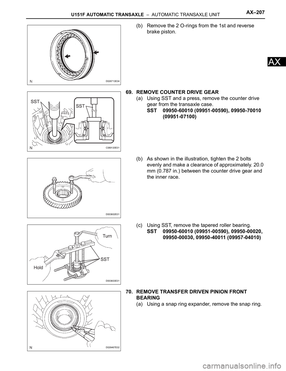
(b) Remove the 2 O-rings from the 1st and reverse
brake piston.
69. REMOVE COUNTER DRIVE GEAR
(a) Using SST and a press, remove the counter drive
gear from the transaxle case.
SST 09950-60010 (09951-00590), 09950-70010
(09951-07100)
(b) As shown in the illustration, tighten the 2 bolts
evenly and make a clearance of approximately. 20.0
mm (0.787 in.) between the counter drive gear and
the inner race.
(c) Using SST, remove the tapered roller bearing.
SST 09950-60010 (09951-00590), 09950-00020,
09950-00030, 09950-40011 (09957-04010)
70. REMOVE TRANSFER DRIVEN PINION FRONT
BEARING
(a) Using a snap ring expander, remove the snap ring.
D026713E04
C089120E01
D003602E01
D003603E01
D026467E02