AUX TOYOTA RAV4 PRIME 2022 Owners Manual
[x] Cancel search | Manufacturer: TOYOTA, Model Year: 2022, Model line: RAV4 PRIME, Model: TOYOTA RAV4 PRIME 2022Pages: 624, PDF Size: 24.01 MB
Page 23 of 624

23Pictorial index
■Ceiling
“SOS” button*1............................................................... ......P.65
Moon roof switch
*1.............................................................P. 247
Panoramic moon roof switch
*1.........................................P.250
Moon roof switch
*1..............................................................P .247
Electronic sunshade switch
*1...........................................P.250
Interior lights
*2............................................................... ....P.404
Personal lights ................................................ ...................P.405
Auxiliary box .................................................. ....................P.409
Vanity mirrors.....................................................................P.414
Sun visors...........................................................................P.414
Inside rear view mirror
*1....................................................P.231
Digital Rear-view Mirror
*1..................................................P.232
Garage door opener switches
*1........................................P.432
*1: If equipped
*2: The illustration shows the fron t, but they are also equipped i n the rear.
A
B
C
D
E
F
G
H
I
Page 158 of 624
1582-2. Charging
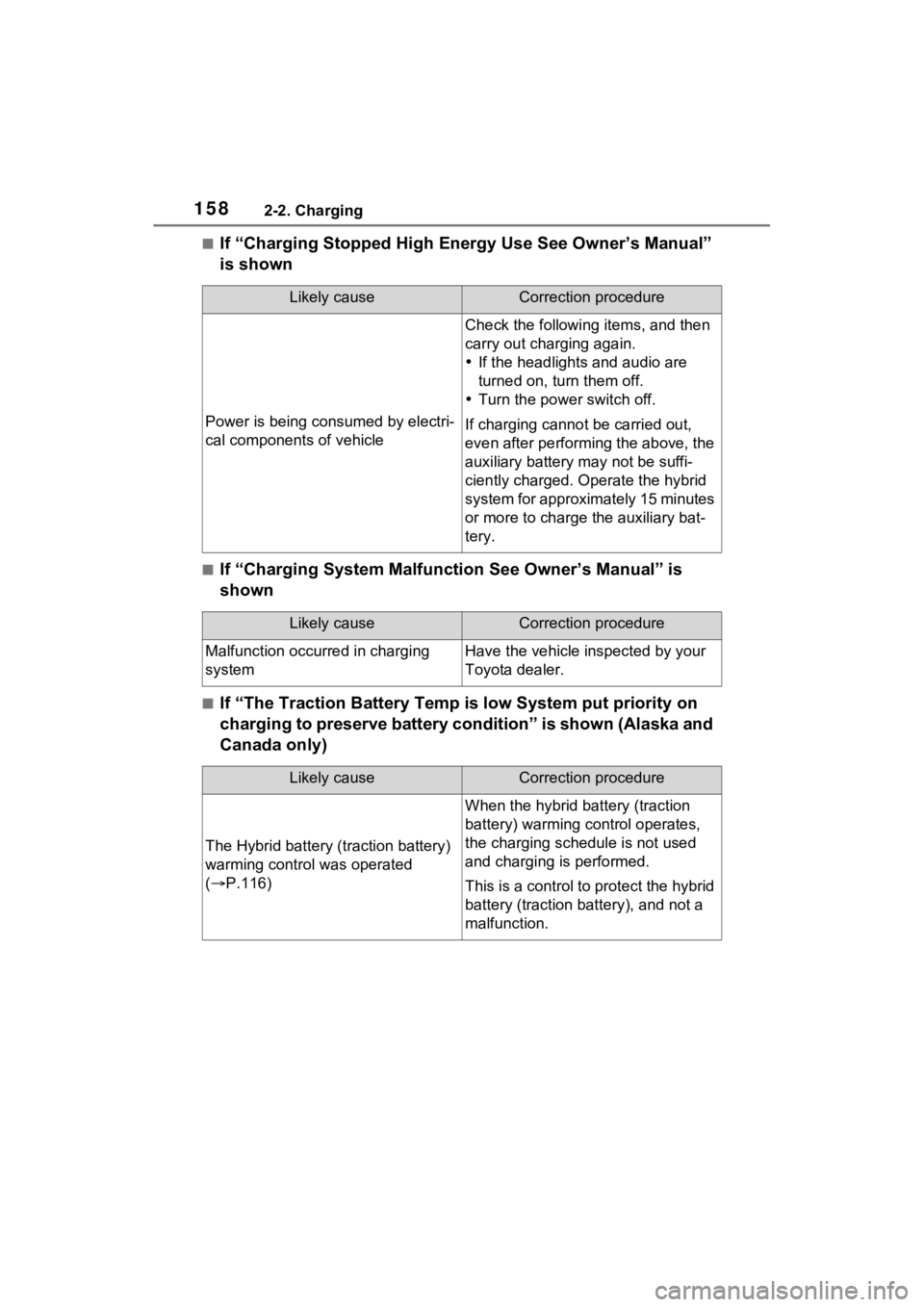
■If “Charging Stopped High Energy Use See Owner’s Manual”
is shown
■If “Charging System Malfunction See Owner’s Manual” is
shown
■If “The Traction Battery Temp is low System put priority on
charging to preserve battery condition” is shown (Alaska and
Canada only)
Likely causeCorrection procedure
Power is being consumed by electri-
cal components of vehicle
Check the following items, and then
carry out charging again.
If the headlights and audio are
turned on, t urn them off.
Turn the power switch off.
If charging cannot be carried out,
even after performing the above, the
auxiliary battery may not be suffi-
ciently charged. Op erate the hybrid
system for approximately 15 minutes
or more to charge the auxiliary bat-
tery.
Likely causeCorrection procedure
Malfunction occurred in charging
systemHave the vehicle inspected by your
Toyota dealer.
Likely causeCorrection procedure
The Hybrid battery ( traction battery)
warming control was operated
( P.116)
When the hybrid battery (traction
battery) warming control operates,
the charging schedule is not used
and charging is performed.
This is a control to protect the hybrid
battery (traction battery), and not a
malfunction.
Page 407 of 624

4076-3. Using the storage features
6
Interior features
6-3.Using the storage features
Open tray (P.410)
Auxiliary boxes ( P.409)
Bottle holders ( P.409)
Console box ( P.408)
Cup holders ( P.408)
Glove box ( P.408)
List of storage features
Location of the storage features
A
B
C
D
E
F
:$51,1*
■Items that should not be left
in the vehicle
Do not leave glasses, lighters or
spray cans in the storage spaces,
as this may cau se the following
when cabin temperature becomes
high:
●Glasses may be deformed by
heat or cracked if they come
into contact with other stored
items.
●Lighters or spray cans may
explode. If they come into con-
tact with other stored items, the
lighter may catch fire or the
spray can may release gas,
causing a fire hazard.
Page 409 of 624

4096-3. Using the storage features
6
Interior features
Front
Rear
■Bottle holders
●When storing a bottle, close the
cap.
●The bottle may not be stored
depending on its size or shape.
Push the lid.
WARNING
■Items unsuitable for the cup
holders
Do not place anything other than
cups or beverage cans in the cup
holders.
Inappropriate items must not be
stored in the cup holders even if
the lid is closed.
Other items may be thrown out of
the holders in the event of an
accident or sudden braking and
cause injury. If possible, cover hot
drinks to prevent burns.
Bottle holders
WARNING
■Items unsuitable for the bottle
holders
Do not place anyth ing other than
a bottle in the bottle holders.
Other items may be thrown out of
the holders in the event of an
accident or sudden braking and
cause injury.
NOTICE
■Items that should be not
stowed in the bottle holders
Do not place open bottles or glass
and paper cups containing liquid
in the bottle holders. The contents
may spill and glasses may break.
Auxiliary box
WARNING
■Caution while driving
Do not leave the auxiliary box
open while driving.
Injuries may resul t in the event of
an accident or sudden braking.
Page 410 of 624

4106-3. Using the storage features
Driver’s side
Front passenger’s side
Center
Vehicles with wireless charger:
P.416WARNING
■Items unsuitable for storing
Do not store items heavier than
0.4 lb. (0.2 kg).
Doing so may cause the auxiliary
box to open and the items inside
may fall out, resulting in an acci-
dent.
Open tray
WARNING
■Items unsuitable for the open
tray
Observe the following precautions
when putting items in the open
tray. Failure to d o so may cause
items to be thrown out of the tray
in the event of s udden braking or
steering. In these cases, the items
may interfere with pedal operation
or cause driver distraction, result-
ing in an accident.
●Do not store ite ms in the tray
that can easily shift or roll out.
●Do not stack items in the tray
higher than the tray’s edge.
●Do not put items in the tray that
may protrude over the tray’s
edge.
Page 453 of 624

4537-3. Do-it-yourself maintenance
7
Maintenance and care
1Pull the hood lock release
lever.
The hood will pop up slightly.
2Push the auxiliary catch lever
to the left and lift the hood. 3
Hold the hood open by insert-
ing the supporting rod into
the slot.
Hood
Release the lock from the
inside of the vehicle to open
the hood.
Opening the hood
WARNING
■Pre-driving check
Check that the hood is fully closed
and locked.
If the hood is not locked properly,
it may open while the vehicle is in
motion and cause an accident,
which may result i n death or seri-
ous injury.
■To prevent burns
Do not touch the pipes when the
compressor is operating or after it
is stopped, because the pipes are
hot.
Touching by hands before the
pipes cool down may cause
burns.
Page 468 of 624

4687-3. Do-it-yourself maintenance
5Press or of the meter
control switches and select
“TPWS”, and then press .
6 Press or to select
“Setting Unit”.
7 Press or to select the
desired unit and then press
.
■Routine tire inflation pressure
checks
The tire pressure warning system
does not replace routine tire inflation
pressure checks. Make sure to
check tire inflation pressure as part
of your routine of daily vehicle
checks.
■Tire inflation pressure
●It may take a few minutes to dis-
play the tire inflation pressure
after the power switch is turned to
ON. It may also take a few min-
utes to display the tire inflation
pressure after inflation pressure
has been adjusted.
●Tire inflation p ressure changes
with temperature.
The displayed values may also be
different from th e values mea-
sured using a tire pressure gauge.
■Situations in which the tire
pressure warning system may
not operate properly
●In the following cases, the tire
pressure warning system may not
operate properly.
• If non-genuine Toyota wheels are
used.
• A tire has been replaced with a tire that is not an OE (Original
Equipment) tire.
• A tire has been replaced with a tire that is not of the specified size.
• Tire chains, etc. are equipped.
• An auxiliary-supported run-flat tire is equipped. • If a window tint that affects the
radio wave signals is installed.
• If there is a lot of snow or ice on
the vehicle, particularly around the
wheels or wheel housings.
• If the tire inflation pressure is
extremely higher than the speci-
fied level.
• If wheel withou t tire pressure
warning valves and transmitters
are used.
• If the ID code on the tire pressure
warning valves and transmitters is
not registered in the tire pressure
warning computer.
●Performance may be affected in
the following situations.
• Near a TV tower, electric power plant, gas station, radio station,
large display, airpo rt or other facil-
ity that generates strong radio
waves or electrical noise
• When carrying a portable radio,
cellular phone, cordless phone or
other wireless communication
device
If tire position information is not
correctly displayed due to the
radio wave conditions, the display
may be corrected by driving and
changing the radio wave condi-
tions.
●When the vehicle is parked, the
time taken for the warning to start
or go off could be extended.
●When tire inflation pressure
declines rapidly for example when
a tire has burst, the warning may
not function.
■Warning performance of the tire
pressure warning system
The warning of the tire pressure
warning system w ill change in
accordance with the conditions
under which it was initialized. For
this reason, the system may give a
warning even if th e tire pressure
does not reach a low enough level,
or if the pressure is higher than the
pressure that was adjusted to when
the system was initialized.
Page 584 of 624

58410-1. For owners
Coussins gonflables SRS latéraux et en rideauCoussins gonflables SRS latéraux avant
Peuvent aider à protéger le torse des occupants des sièges avan t
Coussins gonflables SRS en rideau
• Peuvent aider à protéger principalement la tête des occupants des sièges
latéraux
• Peuvent aider à empêcher les occu pants d’être éjectés du véhicule en
cas de tonneaux
■Composants du système de coussins gonflables SRS
Capteurs d’impact avant
Voyants “AIR BAG ON” et “AIR BAG OFF”
Coussin gonflable du passager avant
Capteurs d’impact latéral (portière avant)
Coussins gonflables en rideau
Limiteurs de force et dispositif s de tension des ceintures de s écu-
rité (sièges avant)
Capteurs d’impact latéral (avant)
Coussins gonflables latéraux
Coussin gonflable du coussin de siège
D
E
A
B
C
D
E
F
G
H
I
Page 585 of 624

58510-1. For owners
10
For owners
Contacteur de boucle de ceinture de sécurité du passager avant
Capteurs d’impact latéral (arrière)
Limiteurs de force et dispositifs de tension des ceintures de s écu-
rité (sièges latéraux arrière)
Capteur de position du siège du conducteur
Coussin gonflable du conducteur
Capteurs du système de classif ication de l’occupant du siège du
passager avant
Coussin gonflable de protection des genoux
Lampe témoin SRS
Module de capteur de coussin gonflable
Votre véhicule est doté de COUSSINS GONFLABLES ÉVOLUÉS
dont la conception s’appuie sur les normes de sécurité des véhi cules
à moteur américains (FMVSS208). Le module de capteur de coussin
gonflable (ECU) contrôle le déplo iement des coussins gonflables en
fonction des informations obtenues des capteurs et d’autres élé-
ments affichés dans le diagramme des composants du système ci-
dessus. Ces informations comprennent des données relatives à la
gravité de l’accident et aux occ upants. Au moment du déploiemen t
des coussins gonflables, une réaction chimique se produit dans les
gonfleurs de coussin gonflable et les coussins gonflables se remplis-
sent rapidement d’un gaz non toxique pour aider à limiter le mo uve-
ment des occupants.J
K
L
M
N
O
P
Q
R
Page 586 of 624

58610-1. For owners
AVERTISSEMENT
■Précautions relatives aux
coussins gonflables SRS
Observez les pré cautions suiva-
ntes en ce qui concerne les cous-
sins gonflables SRS.
Négliger de le faire pourrait occa-
sionner des blessures graves,
voire mortelles.
●Le conducteur et tous les pas-
sagers du véhicule doivent por-
ter leur ceinture de sécurité de
la manière appropriée.
Les coussins gonflables SRS
sont des disposit ifs supplémen-
taires qui doivent être utilisés
avec les ceintures de sécurité.
●Le coussin gonflable SRS du
conducteur se déploie avec une
force considérable et peut occa-
sionner des blessures graves,
voire mortelles, notamment lor-
sque le conducteur se trouve
très près du coussin gonflable.
La National Highway Traffic
Safety Administration (NHTSA),
aux États-Unis, fait les recom-
mandations suivantes :
La zone à risque du coussin gon-
flable du conducteur couvre
2 à 3 in. (50 à 75 mm) de la zone
de déploiement du coussin gon-
flable. Pour assurer une marge de
sécurité suffisante, restez à 10 in.
(250 mm) du coussin gonflable.
Cette distance est mesurée
depuis le centre du volant jusqu’à
votre sternum. Si maintenant
vous vous tenez a ssis à moins de
10 in. (250 mm), vous pouvez
changer votre position de con-
duite de plusieurs manières :
• Reculez votre siège à la posi- tion maximale vous permettant
d’atteindre encore aisément les
pédales.
• Inclinez légèrement le dossier du siège.
Bien que les véhicules soient
conçus différemment, la plupart
des conducteurs peuvent main-
tenir une distance de 10 in.
(250 mm), même si leur siège
se trouve complètement vers
l’avant, simplement en inclinant
un peu le dossier du siège vers
l’arrière. Si la visibilité avant est
moindre après avoir incliné le
dossier de votre siège, utilisez
un coussin ferme et non glissant
pour être assis plus haut ou
relevez le siège s i cette option
est disponible sur votre
véhicule.
• Si votre volant est réglable en hauteur, inclinez-l e vers le bas.
Cela vous permet d’orienter le
coussin gonflable vers votre
buste plutôt que v ers votre tête
et vers votre cou.
Le siège doit être réglé de la
manière recommandée ci-dessus
par la NHTSA, tout en gardant le
contrôle des pédales et du volant,
ainsi que la vue sur les com-
mandes du tableau de bord.