sensor TOYOTA SEQUOIA 2008 2.G User Guide
[x] Cancel search | Manufacturer: TOYOTA, Model Year: 2008, Model line: SEQUOIA, Model: TOYOTA SEQUOIA 2008 2.GPages: 596, PDF Size: 12.93 MB
Page 194 of 596
194 2-4. Using other driving systems
CAUTION
■When the laser radar sensor may not be correctly detecting the vehicle
ahead
● Vehicles that cut in suddenly
● Vehicles traveling at low speeds
● Vehicles that are not moving
● Vehicles with small rear ends (trailers with no load on board etc.)
● Motorcycles traveling in the same lane
■ Conditions under which the vehicle -to-vehicle distance control may
not function correctly
Apply the brakes as necessary in the following conditions as the laser radar
sensor may not be able to correctly detect vehicles ahead, and an accident
may result.
● When water or snow thrown up by the surrounding vehicles hinders the
functioning of the sensor
● When your vehicle is pointing upwards (caused by a heavy load in the lug-
gage compartment, etc.)
● When the road curves or when the lanes are narrow
● When steering wheel operation or your position in the lane is unstable
● When towing a trailer
■ To ensure the laser rada r sensor functions correctly
Do not do the following to the sensor as doing so may cause the sensor not
to function correctly and could result in an accident.
● Stick or attach anything to them
● Leave them dirty
● Disassemble, subject them to strong shocks
● Modify or paint them
● Replace them with non-genuine parts
Page 195 of 596
195
2-4. Using other
driving systems
2
When driving
NOTICE
■Handling the laser radar sensor
Observe the following to ensure the cruise control system can function effec-
tively.
●Keep the sensor clean at all times.
Clean the sensor with a soft cloth so you do not mark or damage them.
● Do not subject the sensor or surrounding area to a strong impact.
If the sensor moves even slightly off position, the system may malfunction.
If the sensor or surrounding area is subject to a strong impact, always
have the area inspected and adjusted by a Toyota dealer.
● Do not disassemble the sensor.
● Do not attach accessories or stickers to the sensor, surrounding area.
Page 196 of 596
196
2-4. Using other driving systems
Intuitive parking assist (if equipped)
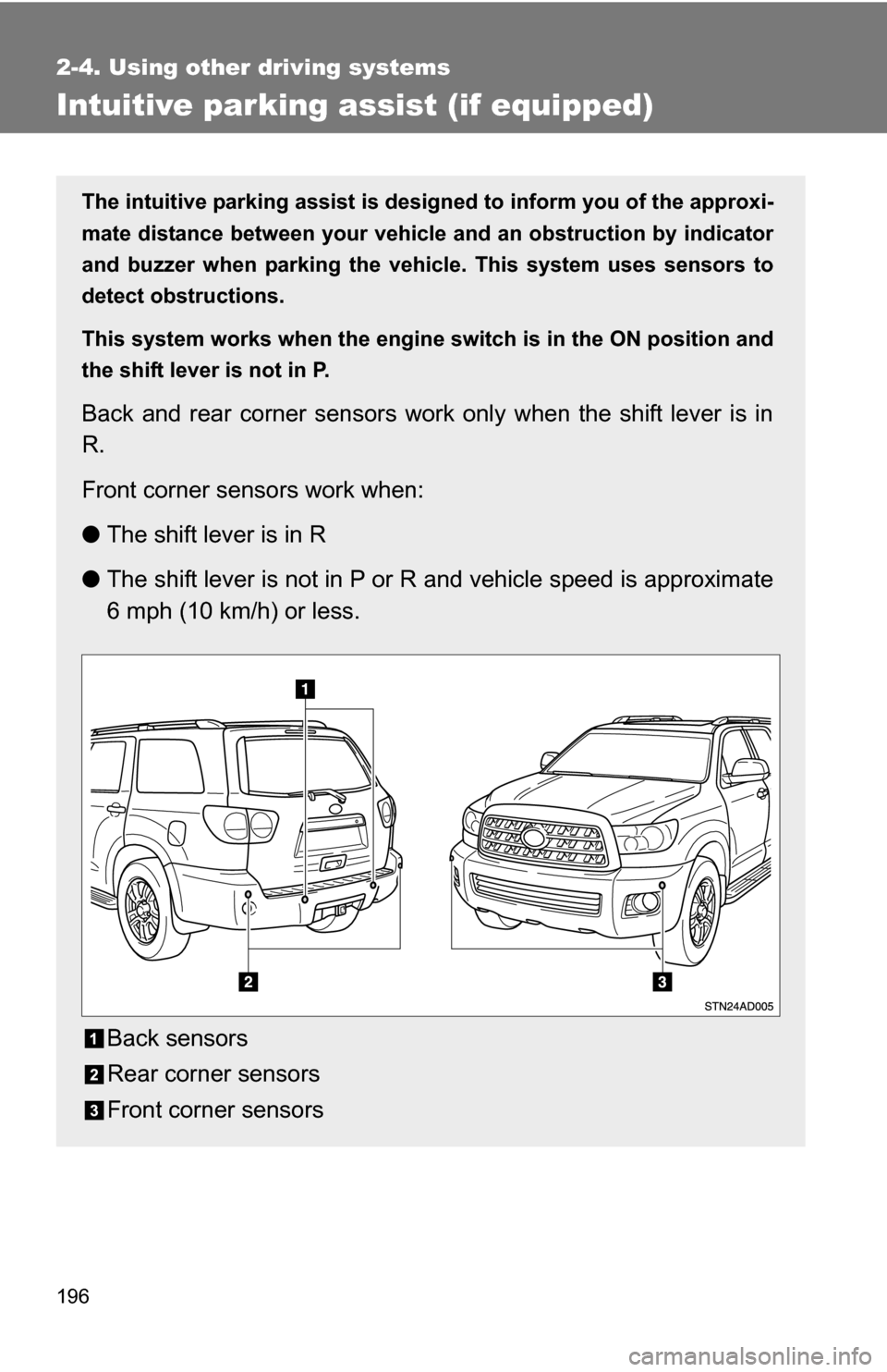
The intuitive parking assist is designed to inform you of the approxi-
mate distance between your vehicle and an obstruction by indicator
and buzzer when parking the veh icle. This system uses sensors to
detect obstructions.
This system works when the engine switch is in the ON position and
the shift lever is not in P.
Back and rear corner sensors work only when the shift lever is in
R.
Front corner sensors work when:
● The shift lever is in R
● The shift lever is not in P or R and vehicle speed is approximate
6 mph (10 km/h) or less.
Back sensors
Rear corner sensors
Front corner sensors
Page 197 of 596
197
2-4. Using other
driving systems
2
When driving
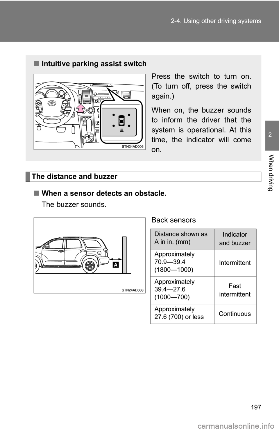
The distance and buzzer
■ When a sensor detects an obstacle.
The buzzer sounds.
Back sensors
■Intuitive parking assist switch
Press the switch to turn on.
(To turn off, press the switch
again.)
When on, the buzzer sounds
to inform the driver that the
system is operational. At this
time, the indicator will come
on.
Distance shown as
A in in. (mm)Indicator
and buzzer
Approximately
70.9—39.4
(1800—1000) Intermittent
Approximately
39.4—27.6
(1000—700) Fast
intermittent
Approximately
27.6 (700) or less Continuous
Page 198 of 596
198 2-4. Using other driving systems
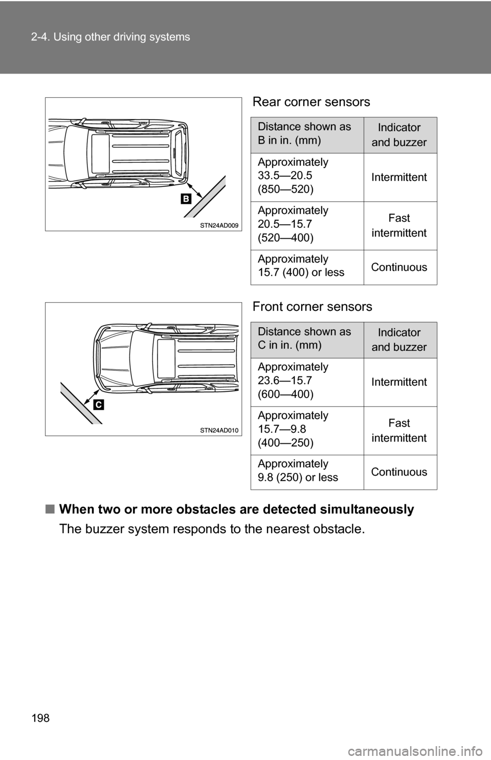
Rear corner sensors
Front corner sensors
■ When two or more obstacles are detected simultaneously
The buzzer system respond s to the nearest obstacle.
Distance shown as
B in in. (mm)Indicator
and buzzer
Approximately
33.5—20.5
(850—520) Intermittent
Approximately
20.5—15.7
(520—400) Fast
intermittent
Approximately
15.7 (400) or less Continuous
Distance shown as
C in in. (mm)Indicator
and buzzer
Approximately
23.6—15.7
(600—400) Intermittent
Approximately
15.7—9.8
(400—250) Fast
intermittent
Approximately
9.8 (250) or less Continuous
Page 199 of 596

199
2-4. Using other
driving systems
2
When driving
Sensors that operate and detection range
The following diagrams show the se nsor detection range. Note that
sensors may not be able to detect obstacles that are extremely close
to the vehicle.
■ Detection range of the sensors
Back sensors
Rear corner sensors
Front corner sensors
Perceptible area
A. Approx. 70.9 in. (1800 mm)
B. Approx. 33.5 in. (850 mm)
C. Approx. 23.6 in. (600 mm)
The diagram shows the detection range of the sensors. Note that the sen-
sors may not be able to detect obstacles that are extremely close to the vehi-
cle.
The range of the sensors may change depending on the shape of the object
etc.
Page 200 of 596
200 2-4. Using other driving systems
■Sensor detection information
●Certain vehicle conditions and the surrounding environment may affect
the ability of a sensor to correctly detect an obstacle. Particular instances
where this may occur are listed below.
• There is dirt, snow or ice on a sensor.
• A sensor is frozen.
• A sensor is covered in any way.
• The vehicle is leaning considerably to one side.
• On an extremely bumpy road, on an incline, on gravel, or on grass.
• The vicinity of the vehicle is noisy due to vehicle horns, motorcycle
engines, air brakes of large vehicles, or other loud noises producing
ultrasonic waves.
• There is another vehicle equipped with parking assist sensors in the vicinity.
• A sensor is coated with a sheet of spray or heavy rain.
• The vehicle is equipped with a fender pole or radio antenna.
• A bumper or sensor receives a strong impact.
• The vehicle is approaching a tall or right-angled curb.
• In harsh sunlight or intense cold weather.
• The area directly under the bumpers is not detected. Objects lower than the sensors or thin stakes etc. may be detected ini-
tially, but as they draw closer, they may cease to be detected.
• A towing hitch is mounted to the vehicle.
• A non-genuine Toyota suspension (lowered suspension etc.) is installed.
• When attaching a two-way radio antenna.
• When a towing eyelet is mounted on your vehicle.
• When the bumper is damaged.
In addition to the examples above, there are instances in which, because of
their shapes, signs and other objects may be judged by a sensor to be closer
than they are.
● The shape of the obstacle may prevent a sensor from detecting it. Pay
particular attention to the following obstacles:
• Wires, fences, ropes, etc.
• Cotton, snow and other materials that absorb radio waves
• Sharply-angled objects
Page 201 of 596
201
2-4. Using other
driving systems
2
When driving
.
• Low obstacles
• Tall obstacles with upper sections projecting outwards in the direction
of your vehicle
• A person near the vehicle (depending on the type of clothes worn)
• When the bumper is damaged.
■ Certification (Canada only)
This ISM device complies with Canadian ICES-001.
■ If the indicator is continuously on
Have the vehicle inspected by your Toyota dealer.
■ If the indicator remains blinking but do not sound the buzzer
Clean the sensors with soft cloth.
CAUTION
■Caution when using the intuitive parking assist
Observe the following precautions.
Failure to do so may result in the vehicle being unable to be driven safely
and possibly cause an accident.
●Do not use the sensor at speeds in excess of 6 mph (10 km/h).
● Do not attach any accessories within the sensor range.
NOTICE
■Notes when washing the vehicle
Do not apply intensive bursts of water or steam to the sensor area.
Doing so may result in the sensor malfunctioning.
Page 419 of 596
419
3-7. Other interior features
3
Interior features
NOTICE
■
To avoid the compass malfunctions
Do not place magnets or any metal objects near the inside rear view mirror.
Doing this may cause a malfunction of the compass sensor.
■ To ensure normal operation of the compass
●Do not perform circling calibration of the compass in a place where the
earth's magnetic field is subject to interference by artificial magnetic fields.
● During calibration, do not operate electric systems (moon roof, power win-
dows, etc.) as they may interfere with the calibration.
Page 503 of 596
5
When trouble arises
503
5-1. Essential information
Event data recorder
In a crash or a near car crash eventThe SRS airbag sensor assembly contains the EDR. In a crash or a
near car crash event, this device may record some or all of the follow-
ing information:
● Engine speed
● Whether the brake pedal was applied or not
● Vehicle speed
● To what extent the accelerator pedal was depressed
● Position of the transmission shift lever
● Whether the driver and front passenger wore seat belts or not
● Driver’s seat position
● Front passenger’s occupant classification
● SRS airbag deployment data
● SRS airbag system diagnostic data
The information above is intended to be used for the purpose of
improving vehicle safety performance. Unlike general data recorders,
the EDR does not record sound data such as conversation between
passengers.
Your vehicle has computers that monitor and control certain aspects
of your vehicle. These computers assi st in driving and maintaining
optimal vehicle performance.
Besides storing data useful for tr oubleshooting, there is an event
data recorder (EDR) that records data in a crash or a near car
crash event.