flat tire TOYOTA SEQUOIA 2022 Service Manual
[x] Cancel search | Manufacturer: TOYOTA, Model Year: 2022, Model line: SEQUOIA, Model: TOYOTA SEQUOIA 2022Pages: 592, PDF Size: 10.82 MB
Page 498 of 592

4987-2. Steps to take in an emergency
SEQUOIA_OM_USA_OM0C047U
Chock the tires.
Slightly loosen the wheel nuts
(one turn).
Assemble the jack handle
extension as shown.
Replacing a flat tire
1
Flat tireWheel chock positions
FrontLeft-hand sideBehind the rear right-hand side tire
Right-hand sideBehind the rear left-hand side tire
RearLeft-hand sideIn front of the front right-hand side tire
Right-hand sideIn front of the front left-hand side tire
2
3
Page 500 of 592

5007-2. Steps to take in an emergency
SEQUOIA_OM_USA_OM0C047U
WARNING
■Replacing a flat tire
●Observe the following precautions.
Failure to do so may result in serious injury:
• Lower the spare tire completely to the ground before removing it
from under the vehicle.
• Do not try to remove the wheel ornament by hand. Take due care in
handling the ornament to avoi d unexpected personal injury.
• Do not attach a heavily damaged wheel ornament, as it may fly off
the wheel while the vehicle is moving.
• Do not touch the disc wheels or the area around the brakes imm edi-
ately after the vehi cle has been driven.
After the vehicle has been driven the disc wheels and the area
around the brakes will be extremely hot. Touching these areas w ith
hands, feet or other body parts while changing a tire, etc. may result
in burns.
●Failure to follow these precautions could cause the wheel nuts to
loosen and the t ire to fall off, resulting in death or serious injury.
• Have the wheel nuts tightened with a torque wrench as soon as pos-
sible after changing wheels.
Steel wheel: 154 ft·lbf (209 N·m, 21.3 kgf·m)
Aluminum wheel: 97 ft·lbf (131 N·m, 13.4 kgf·m)
• When installing a tire, only use wheel nuts that have been spe cifi-
cally designed for that wheel.
• If there are any cracks or deformations in the bolt screws, nu t
threads or bolt holes of the wheel, have the vehicle inspected by
your Toyota dealer.
• When installing the wheel nuts, be sure to install them with t he
tapered ends facing inward.
Page 502 of 592

5027-2. Steps to take in an emergency
SEQUOIA_OM_USA_OM0C047U
Lower the vehicle.
Firmly tighten each wheel nut
two or three times in the order
shown in the illustration.
Tightening torque
154 ft·lbf (209 N·m, 21.3 kgf·m)
*
*: When used on aluminum wheel,
apply 97 ft·lbf (131 N·m, 13.4 kgf·m)
3
4
WARNING
■Stowing the flat tire
Failure to follow steps listed under stowing the tire may result in damage
to the spare tire carrier and lose of the tire, which could res ult in death or
serious injury.
Page 503 of 592

5037-2. Steps to take in an emergency
7
When trouble arises
SEQUOIA_OM_USA_OM0C047U
Remove the center wheel ornament by pushing from the reverse
side.
Lay down the tire with the valve
stem facing up and install the
holding bracket, inserting the
claw into the wheel lug nut hole.
Turn the jack handle extension
clockwise to take up slack in
the chain.
Then, check to ensure the claw
is in the wheel lug nut hole and
the holding brack et is centered
in the wheel hub.
Claw
Holding bracket
While raising, secure the tire,
taking care that the tire goes
straight up without catching on
any surrounding part to prevent
it from flying forward during a
collision or sudden braking.
Tightening torque:
34.7 ft·lbf (46.6 N·m, 4.8 kgf·m)
Stowing the flat/spare tire, jack and tools
1
incorrect
correct
O
Page 504 of 592
5047-2. Steps to take in an emergency
SEQUOIA_OM_USA_OM0C047U
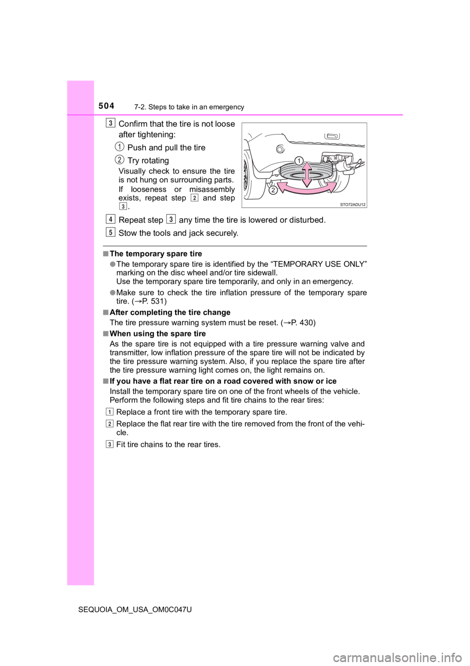
Confirm that the tire is not loose
after tightening:Push and pull the tire
Try rotating
Visually check to ensure the tire
is not hung on su rrounding parts.
If looseness or misassembly
exists, repeat step and step .
Repeat step any time the tire is lowered or disturbed.
Stow the tools and jack securely.
■The temporary spare tire
●The temporary spare tire is iden tified by the “TEMPORARY USE ON LY ”
marking on the disc wheel and/or tire sidewall.
Use the temporary spare tire temp orarily, and only in an emergency.
●Make sure to check the tire inflation pressure of the temporary spare
tire. ( P. 5 3 1 )
■After completing the tire change
The tire pressure warni ng system must be reset. ( P. 430)
■When using the spare tire
As the spare tire is not equipped with a tire pressure warning valve and
transmitter, low inflation pre ssure of the spare tire will not be indicated by
the tire pressure warning system. Also, if you replace the spar e tire after
the tire pressure wa rning light comes on, the light remains on.
■If you have a flat rear tire on a road covered with snow or ice
Install the temporary spare tire on one of the front wheels of the vehicle.
Perform the following steps and fit tire chains to the rear tires:
Replace a front tire with the temporary spare tire.
Replace the flat rear tire with the tire removed from the front of the vehi-
cle.
Fit tire chains to the rear tires.
3
2
3
43
5
1
2
3
Page 506 of 592

5067-2. Steps to take in an emergency
SEQUOIA_OM_USA_OM0C047U
NOTICE
■Do not drive the vehicle with a flat tire
Do not continue driving with a flat tire.
Driving even a short distance with a flat tire can damage the tire and the
wheel beyond repair.
■Driving with tire chains a nd the temporary spare tire
Do not fit tire chains to t he temporary spare tire.
Tire chains may damage the vehicle body and adversely affect dr iving
performance.
■When stowing the flat tire
Ensure that there is no object c aught between the tire and the vehicle
underbody.
■When assembling the jack handle extension
Insert the square head securely until you hear a click. Otherwise the
extension may come off and it may damage the paint or vehicle bo d y.
■When replacing the tires
When removing or fitting the wheels, tires or the tire pressure warning
valve and transmitter, contact your Toyota dealer as the tire p ressure
warning valve and transmitter may be damaged if not handled correctly.
■To avoid damage to the tire pressure warning valves and transmi t-
ters
When a tire is repaired with liquid sealants, the tire pressure warning valve and transmitter may not operate properly. If a liquid sea lant is
used, contact your Toyota dealer or other qualified service shop as soon
as possible. Make sure to replace the tire pressure warning valve and
transmitter when replacing the tire. ( P. 429)
Page 531 of 592

5318-1. Specifications
8
Vehicle specifications
SEQUOIA_OM_USA_OM0C047U
Ty p e A
Ty p e B
Spare tire (Type A)
Spare tire (Type B)
Tires and wheels
Tire sizeP275/65R18 114T
Tire inflation pressure
(Recommended cold tire
inflation pressure)Front tires:
33 psi (230 kPa, 2.3 kgf/cm2 or bar)
Rear tires:
33 psi (230 kPa, 2.3 kgf/cm
2 or bar)
Wheel size 18 8J
Wheel nut torque 97 ft·lbf (131 N·m, 13.4 kgf·m)
Tire size P275/55R20 111H
Tire inflation pressure
(Recommended cold tire
inflation pressure)Front tires:
30 psi (210 kPa, 2.1 kgf/cm2 or bar)
Rear tires:
33 psi (230 kPa, 2.3 kgf/cm
2 or bar)
Wheel size 20 8J
Wheel nut torque 97 ft·lbf (131 N·m, 13.4 kgf·m)
Tire size P255/70R18 112T
Tire inflation pressure
(Recommended cold tire
inflation pressure)33 psi (230 kPa, 2.3 kgf/cm2 or bar)
Wheel size
18 8J
Wheel nut torque 154 ft·lbf (209 N·m, 21.3 kgf·m)
Tire size P275/65R18 114T
Tire inflation pressure
(Recommended cold tire
inflation pressure)33 psi (230 kPa, 2.3 kgf/cm2 or bar)
Wheel size
18 8J
Wheel nut torque 154 ft·lbf (209 N·m, 21.3 kgf·m)
Page 536 of 592

5368-1. Specifications
SEQUOIA_OM_USA_OM0C047U
Tire information
Tire size( P. 538)
DOT and Tire Identification Number (TIN) ( P. 537)
Location of treadwear indicators ( P. 428)
Tire ply composition and materials
Plies are layers of rubber-coated parallel cords. Cords are the strands
which form the p lies in a tire.
Uniform tire quality grading
For details, see “Uniform Tire Q uality Grading” that follows.
Load limit at maximum cold tire inflation pressure ( P. 542)
Maximum cold tire in flation pressure ( P. 542)
This means the press ure to which a tire may be inflated.
TUBELESS or TUBE TYPE
A tubeless tire does not have a tube and air is directly put into the tire.
A tube type tire has a tube insi de the tire and the tube mainta ins the air
pressure.
Typical tire symbols
Page 541 of 592

5418-1. Specifications
8
Vehicle specifications
SEQUOIA_OM_USA_OM0C047U■
Temperature A, B, C
The temperature grades are A (
the highest), B, and C, representing
the tire’s resistance to the ge neration of heat and its ability to dissi-
pate heat when tested under contr olled conditions on a specified
indoor laboratory test wheel.
Sustained high temperature can c ause the material of the tire to
degenerate and reduce tire life, and excessive temperature can lead
to sudden tire failure.
Grade C corresponds to a level of performance which all passeng er
car tires must meet under the Fe deral Motor Vehicle Safety Stan-
dard No. 109.
Grades B and A represent higher levels of performance on the labo-
ratory test wheel than the minimum required by law.
Warning: The temperature grades of a tire assume that it is pro perly
inflated and not overloaded.
Excessive speed, underinflation, or excessive loading, either sepa-
rately or in combination, can c ause heat buildup and possible t ire
failure.
Page 542 of 592
5428-1. Specifications
SEQUOIA_OM_USA_OM0C047U
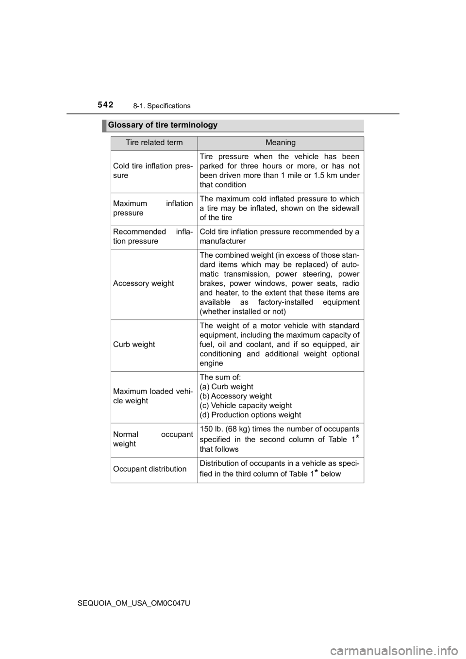
Glossary of tire terminology
Tire related termMeaning
Cold tire inflation pres-
sure
Tire pressure when the vehicle has been
parked for three hours or more, or has not
been driven more than 1 mile or 1.5 km under
that condition
Maximum inflation
pressureThe maximum cold inflated pressure to which
a tire may be inflated, shown on the sidewall
of the tire
Recommended infla-
tion pressureCold tire inflation pressure recommended by a
manufacturer
Accessory weight
The combined weight (in excess of those stan-
dard items which may be replaced) of auto-
matic transmission, power steering, power
brakes, power windows, power seats, radio
and heater, to the extent that these items are
available as factory-installed equipment
(whether installed or not)
Curb weight
The weight of a motor vehicle with standard
equipment, including the maximum capacity of
fuel, oil and coolant, and if so equipped, air
conditioning and additional weight optional
engine
Maximum loaded vehi-
cle weight
The sum of:
(a) Curb weight
(b) Accessory weight
(c) Vehicle capacity weight
(d) Production options weight
Normal occupant
weight150 lb. (68 kg) times the number of occupants
specified in the second column of Table 1
*
that follows
Occupant distributionDistribution of occupants in a vehicle as speci-
fied in the third column of Table 1
* below