brakes TOYOTA SEQUOIA HYBRID 2023 Owner's Guide
[x] Cancel search | Manufacturer: TOYOTA, Model Year: 2023, Model line: SEQUOIA HYBRID, Model: TOYOTA SEQUOIA HYBRID 2023Pages: 628, PDF Size: 14.27 MB
Page 402 of 628
4024-6. Driving tips
Owners Manual_USA_M0C043_en
Perform the following according
to the driving conditions:
Do not try to forcibly open a
window or move a wiper that
is frozen. Pour warm water
over the frozen area to melt
the ice. Wipe away the water
immediately to prevent it from
freezing.
To ensure proper operation of
the climate control system
fan, remove any snow that
has accumulated on the air
inlet vents in front of the wind-
shield.
Check for and remove any
excess ice or snow that may
have accumulated on the
exterior lights, vehicle’s roof,
chassis, around the tires or on
the brakes.
Remove any snow or mud
from the bottom of your shoes
before getting in the vehicle. Accelerate the vehicle slowly,
keep a safe distance between
you and the vehicle ahead, and
drive at a reduced speed suit-
able to road conditions.
Turn automatic mode of the
parking brake off.
Otherwise, the parking brake
may freeze and not be able to
be released automatically.
Also, avoid using the following
as the parking brake may
operate automatically, even if
automatic mode is off.
• Brake hold system
Park the vehicle and move
the shift lever to P without set-
ting the parking brake. The
parking brake may freeze up,
preventing it from being
released. If the vehicle is
parked without setting the
parking brake, make sure to
block the wheels.
Failure to do so may be dan-
gerous because it may cause
the vehicle to move unexpect-
edly, possibly leading to an
accident.
When the parking brake is in
automatic mode, release the
parking brake after shifting
the shift lever to P.( P.223)
NOTICE
■Repairing or replacing snow
tires
Request repairs or replacement of
snow tires from Toyota dealers or
legitimate tire retailers.
This is because the removal and
attachment of snow tires affects
the operation of the tire pressure
warning valves and transmitters.
Before driving the vehicle
When driving the vehicle
When parking the vehicle
Page 403 of 628
4034-6. Driving tips
Owners Manual_USA_M0C043_en
4
Driving
If the vehicle is parked without
setting the parking brake,
confirm that the shift lever
cannot be moved out of P.
If the vehicle is left parked
with the brakes damp in cold
temperatures, there is a pos-
sibility of the brakes freezing.
Vehicles without 285/65R18
tires
Use the correct tire chain size
when mounting the tire chains.
Chain size is regulated for each
tire size.
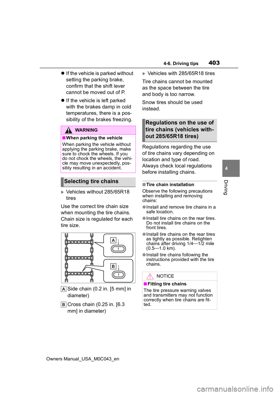
Side chain (0.2 in. [5 mm] in
diameter)
Cross chain (0.25 in. [6.3
mm] in diameter)
Vehicles with 285/65R18 tires
Tire chains cannot be mounted
as the space between the tire
and body is too narrow.
Snow tires should be used
instead.
Regulations regarding the use
of tire chains vary depending on
location and type of road.
Always check local regulations
before installing chains.
■Tire chain installation
Observe the followi ng precautions
when installing and removing
chains:
●Install and remove tire chains in a
safe location.
●Install tire chains on the rear tires.
Do not install ti re chains on the
front tires.
●Install tire chains on the rear tires
as tightly as possible. Retighten
chains after driving 1/4 1/2 mile
(0.5 1.0 km).
●Install tire chains following the
instructions provided with the tire
chains.
WARNING
■When parking the vehicle
When parking the v ehicle without
applying the parking brake, make
sure to chock the wheels. If you
do not chock the wheels, the vehi-
cle may move une xpectedly, pos-
sibly resulting in an accident.
Selecting tire chains
Regulations on the use of
tire chains (vehicles with-
out 285/65R18 tires)
NOTICE
■Fitting tire chains
The tire pressure warning valves
and transmitters may not function
correctly when tire chains are fit-
ted.
Page 451 of 628
4516-1. Maintenance and care
Owners Manual_USA_M0C043_en
6
Maintenance and care
brakes several times to dry the
parts.
■Bumpers and wh eel arch mold-
ings
Do not scrub with abrasive cleaners.
■Plated portions
If dirt cannot be removed, clean the
parts as follows:
●Use a soft cloth dampened with an
approximately 5% solution of neu-
tral detergent and water to clean
the dirt off.
●Wipe the surface with a dry, soft
cloth to remove any remaining
moisture.
●To remove oily deposits, use alco-
hol wet wipes or a similar product.
WARNING
■When washing the vehicle
Do not apply water to the inside of
the engine compartment. Doing
so may cause the electrical com-
ponents, etc. to catch fire.
■Precautions regarding the
exhaust pipe
Exhaust gases cause the exhaust
pipe to become quite hot. When
washing the vehicle, be careful
not to touch the pipe until it has
cooled sufficiently, as touching hot
exhaust pipe can cause burns.
■When cleaning the windshield
(vehicles with rain-sensing
windshield wipers)
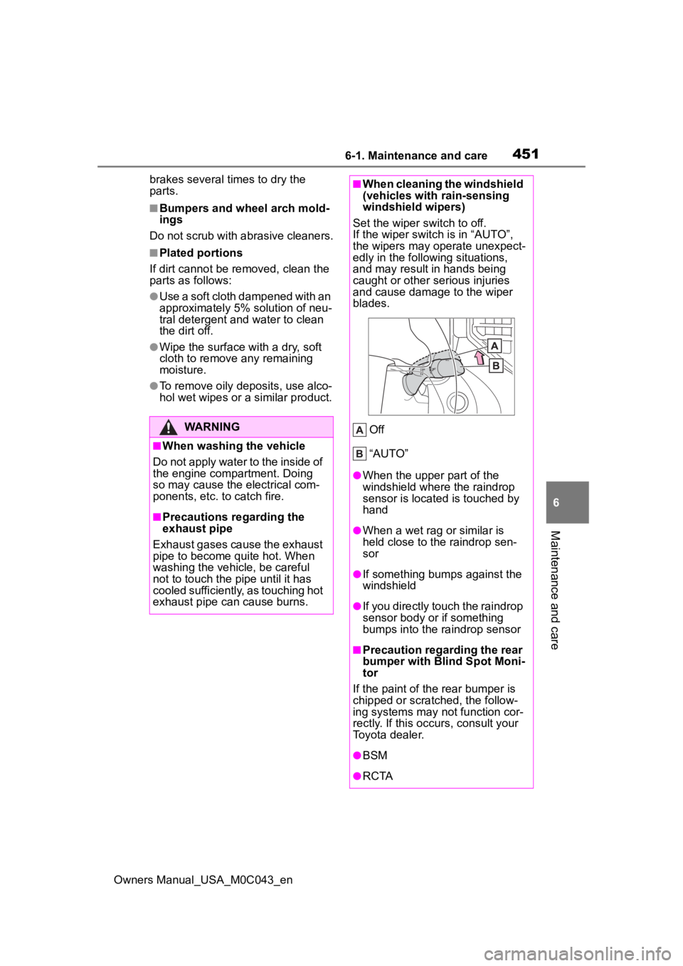
Set the wiper switch to off.
If the wiper switch is in “AUTO”,
the wipers may operate unexpect-
edly in the following situations,
and may result in hands being
caught or other serious injuries
and cause damage to the wiper
blades.
Off
“AUTO”
●When the upper part of the
windshield where the raindrop
sensor is located is touched by
hand
●When a wet rag or similar is
held close to the raindrop sen-
sor
●If something bumps against the
windshield
●If you directly touch the raindrop
sensor body or if something
bumps into the ra indrop sensor
■Precaution regarding the rear
bumper with Blind Spot Moni-
tor
If the paint of th e rear bumper is
chipped or scratched, the follow-
ing systems may not function cor-
rectly. If this occurs, consult your
Toyota dealer.
●BSM
●R C TA
Page 458 of 628
4586-2. Maintenance
Owners Manual_USA_M0C043_en
Exhaust sys-
temThere should not
be any fumes or
strange sounds.
Radiator/con-
denser/inter-
cooler
The radiator, con-
denser and inter-
cooler should be
free from foreign
objects. (P.469)
Washer fluid
Is there sufficient
washer fluid?
( P.470)
Vehicle interior
ItemsCheck points
12-volt batteryCheck the connec-
tions. ( P.471)
Accelerator
pedal
• The accelerator
pedal should
move smoothly
(without uneven
pedal effort or
catching).
Automatic
transmission
“Park” mecha-
nism
• When parked on a slope and the
shift lever is in P,
is the vehicle
securely
stopped?
ItemsCheck points
Brake pedal
• Does the brake pedal move
smoothly?
• Does the brake pedal have
appropriate
clearance from
the floor?
• Does the brake pedal have the
correct amount
of free play?
Brakes
• The vehicle should not pull to
one side when
the brakes are
applied.
• The brakes should work
effectively.
• The brake pedal should not feel
spongy.
• The brake pedal should not get
too close to the
floor when the
brakes are
applied.
Head
restraints
• Do the head restraints move
smoothly and
lock securely?
Indica-
tors/buzzers
• Do the indica-tors and buzzers
function prop-
erly?
ItemsCheck points
Page 518 of 628
5187-2. Steps to take in an emergency
Owners Manual_USA_M0C043_en
WARNING
●If the tire pressure warning light
comes on even after tire infla-
tion pressure adjustment, it is
probable that you have a flat
tire. Check the tires. If a tire is
flat, change it with the spare tire
and have the flat tire repaired by
the nearest Toy ota dealer.
●Avoid abrupt maneuvering and
braking.
If the vehicle tires deteriorate,
you could lose control of the
steering wheel or the brakes.
■If a blowout or sudden air
leakage should occur
The tire pressure warning system
may not activate immediately.
■Maintenance of the tires
Each tire, including the spare (if
provided), should be checked
monthly when cold and inflated to
the inflation pressure recom-
mended by the vehicle manufac-
turer on the vehicle placard or tire
inflation pressure label (tire and
load information label). (If your
vehicle has tires of a different size
than the size indicated on the
vehicle placard or tire inflation
pressure label [tire and load infor-
mation label], you should deter-
mine the proper tire inflation
pressure for those tires.)
As an added safety feature, your
vehicle has been equipped with a
tire pressure monitoring system
(TPMS-tire pressure warning sys-
tem) that illuminates a low tire
pressure telltale (tire pressure
warning light) w hen one or more
of your tires is s ignificantly under-
inflated. Accordingly, when the
low tire pressure te lltale (tire pres-
sure warning light) illuminates,
you should stop and check your
tires as soon as possible, and
inflate them to the proper pres-
sure. Driving on a significantly
under-inflated tire causes the tire
to overheat and can lead to tire
failure. Under-inflation also
reduces fuel efficiency and tire
tread life, and may affect the vehi-
cle’s handling and stopping ability.
Please note that the TPMS (tire
pressure warning system) is not a
substitute for proper tire mainte-
nance, and it is the driver’s
responsibility to m aintain correct
tire pressure, even if under-infla-
tion has not reached the level to
trigger illumination of the TPMS
low tire pressure te lltale (tire pres-
sure warning light).
Your vehicle has also been
equipped with a TPMS (tire pres-
sure warning system) malfunc-
tion indicator to indicate when the
system is not operating properly.
The TPMS (tire pressure warning
system) malfunction indicator is
combined with the low tire pres-
sure telltale (tire pressure warning
light). When the system detects a
malfunction, the te lltale will flash
for approximately one minute and
then remain continuously illumi-
nated. This sequence will con-
tinue upon subsequent vehicle
start-ups as long as the malfunc-
tion exists. When the malfunction
indicator is illuminated, the sys-
tem may not be ab le to detect or
signal low tire pressure as
intended.
Page 528 of 628
5287-2. Steps to take in an emergency
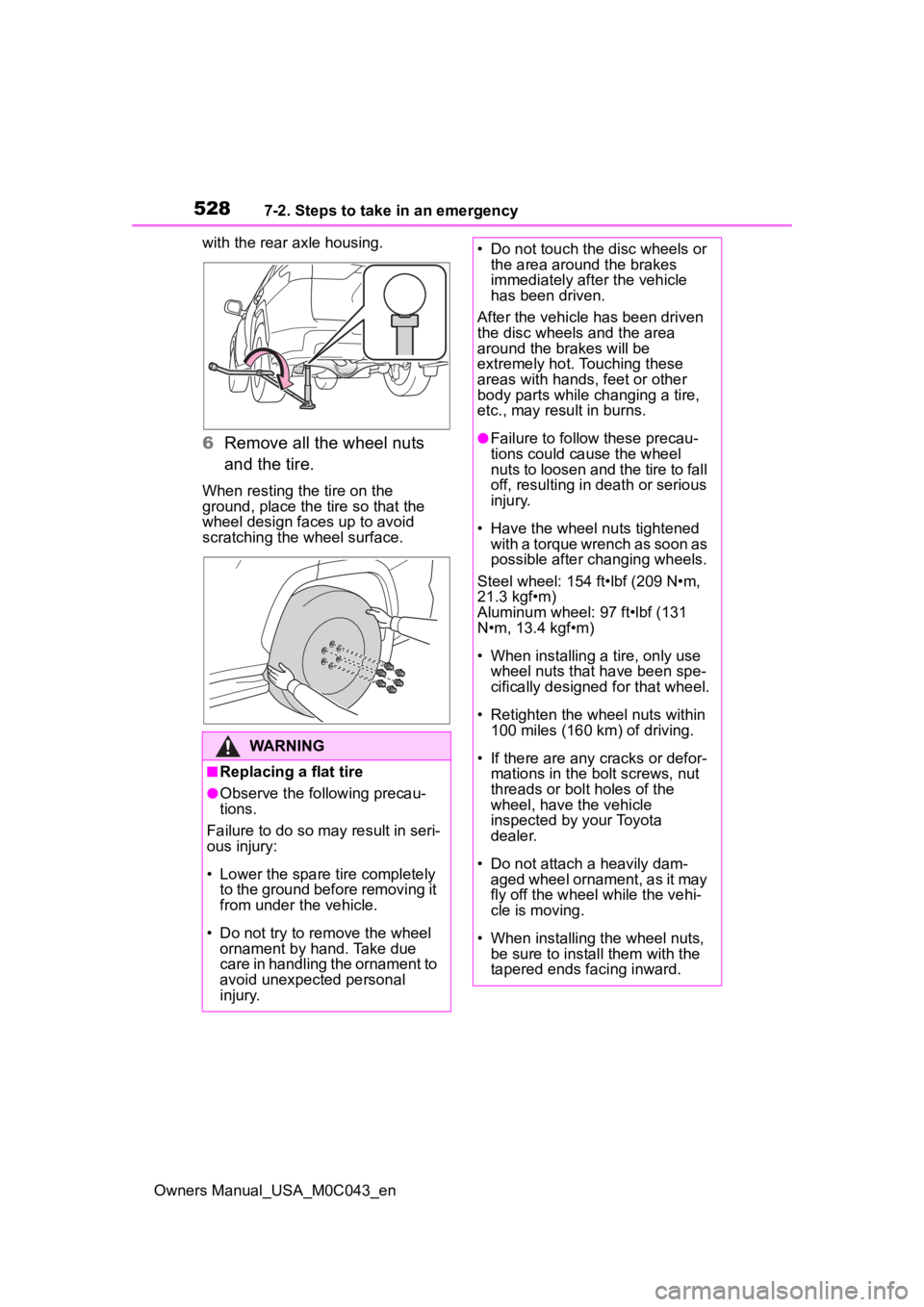
Owners Manual_USA_M0C043_enwith the rear axle housing.
6
Remove all the wheel nuts
and the tire.
When resting the tire on the
ground, place the tire so that the
wheel design faces up to avoid
scratching the wheel surface.
WARNING
■Replacing a flat tire
●Observe the following precau-
tions.
Failure to do so may result in seri-
ous injury:
• Lower the spare tire completely to the ground before removing it
from under the vehicle.
• Do not try to rem ove the wheel
ornament by hand. Take due
care in handling the ornament to
avoid unexpected personal
injury.
• Do not touch the disc wheels or the area around the brakes
immediately after the vehicle
has been driven.
After the vehicle has been driven
the disc wheels and the area
around the br akes will be
extremely hot. Touching these
areas with hands, feet or other
body parts while changing a tire,
etc., may result in burns.
●Failure to follow these precau-
tions could cause the wheel
nuts to loosen and the tire to fall
off, resulting in death or serious
injury.
• Have the wheel nuts tightened
with a torque wrench as soon as
possible after changing wheels.
Steel wheel: 154 ft•lbf (209 N•m,
21.3 kgf•m)
Aluminum wheel: 97 ft•lbf (131
N•m, 13.4 kgf•m)
• When installing a tire, only use wheel nuts that have been spe-
cifically designed for that wheel.
• Retighten the wheel nuts within 100 miles (160 km) of driving.
• If there are any cracks or defor- mations in the bolt screws, nut
threads or bolt holes of the
wheel, have the vehicle
inspected by your Toyota
dealer.
• Do not attach a heavily dam- aged wheel ornament, as it may
fly off the wheel while the vehi-
cle is moving.
• When installing the wheel nuts, be sure to install them with the
tapered ends facing inward.
Page 554 of 628
5548-1. Specifications
Owners Manual_USA_M0C043_en
Your Toyota vehicle is filled with “Toyota Genuine Differential Gear
Oil” at the factory.
Use Toyota approved “Toyota Genuine Differential Gear Oil” or an
equivalent oil of matching quality to satisfy the above specifi cation.
Please contact your Toyota dealer for further details.
*1: Minimum pedal clearance when depressed with a force of 110 lbf (490 N,
50 kgf) while the hybrid system is running.
*2: Make sure to confirm that the brake warning light (yellow) doe s not illumi-
nate. (If the brake warning light illuminates, refer to P.509.)
Differential
Oil capacity
Front (4WD
models)1.4 qt. (1.29 L, 1.1 Imp.qt.)
Rear
Without rear differential lock system
6.0 qt. (5.73 L , 5.0 Imp.qt.)
With rear differential lock system
5.8 qt. (5.51 L, 4.8 Imp.qt.)
Oil type and viscosityToyota Genuine Differential Ge ar Oil LT
75W-85 GL-5 or equivalent
Brakes
Pedal clearance*13.6 in. (90.8 mm) Min.
Pedal free play0.04 0.24 in. (1 6 mm)
Brake pad wear limit0.04 in. (1 mm)
Parking brake indicator*2
When pulling the parking brake switch for
1 to 2 seconds: comes on
When pushing the parking brake switch for
1 to 2 seconds: turns off
Fluid type• FMVSS No.116 DOT 3 or SAE J1703
• FMVSS No.116 DOT 4 or SAE J1704
Page 564 of 628
5648-1. Specifications
Owners Manual_USA_M0C043_en
Glossary of tire terminology
Tire related termMeaning
Cold tire inflation pressure
Tire pressure when the vehicle has been
parked for three hours or more, or has not
been driven more than 1 mile or 1.5 km
under that condition
Maximum inflation pressure
The maximum cold inf lated pressure to
which a tire may be inflated, shown on the
sidewall of the tire
Recommended inflation pres-
sureCold tire inflation pressure recommended
by a manufacturer
Accessory weight
The combined weight (in excess of those
standard items which may be replaced) of
automatic transmission, power steering,
power brakes, power windows, power
seats, radio and heater, to the extent that
these items are ava ilable as factory-
installed equipment (whether installed or
not)
Curb weight
The weight of a moto r vehicle with stan-
dard equipment, including the maximum
capacity of fuel, oil and coolant, and if so
equipped, air conditioning and additional
weight optional engine
Maximum loaded vehicle
weight
The sum of:
(a) Curb weight
(b) Accessory weight
(c) Vehicle capacity weight
(d) Production options weight
Normal occupant weight
150 lb. (68 kg) times the number of occu-
pants specified in the second column of
Ta b l e 1
* that follows
Occupant distribution
Distribution of occupants in a vehicle as
specified in the third column of Table 1
*
below
Page 565 of 628
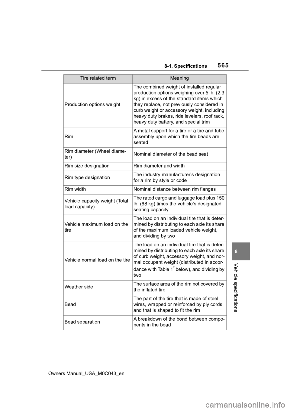
5658-1. Specifications
Owners Manual_USA_M0C043_en
8
Vehicle specifications
Production options weight
The combined weight of installed regular
production options weighing over 5 lb. (2.3
kg) in excess of the standard items which
they replace, not previously considered in
curb weight or accessory weight, including
heavy duty brakes, ride levelers, roof rack,
heavy duty battery, and special trim
Rim
A metal support for a tire or a tire and tube
assembly upon which the tire beads are
seated
Rim diameter (Wheel diame-
ter)Nominal diameter o f the bead seat
Rim size designationRim diameter and width
Rim type designationThe industry manufacturer’s designation
for a rim by style or code
Rim widthNominal distance between rim flanges
Vehicle capacity weight (Total
load capacity)The rated cargo and luggage load plus 150
lb. (68 kg) times the vehicle’s designated
seating capacity
Vehicle maximum load on the
tire
The load on an individua l tire that is deter-
mined by distributing to each axle its share
of the maximum loaded vehicle weight,
and dividing by two
Vehicle normal load on the tire
The load on an individua l tire that is deter-
mined by distributing to each axle its share
of curb weight, accessory weight, and nor-
mal occupant weight (distributed in accor-
dance with Table 1
* below), and dividing by
two
Weather sideThe surface area of the rim not covered by
the inflated tire
Bead
The part of the tire that is made of steel
wires, wrapped or reinforced by ply cords
and that is shaped to fit the rim
Bead separationA breakdown of the bond between compo-
nents in the bead
Tire related termMeaning