engine coolant TOYOTA SIENNA 2007 Service Service Manual
[x] Cancel search | Manufacturer: TOYOTA, Model Year: 2007, Model line: SIENNA, Model: TOYOTA SIENNA 2007Pages: 3000, PDF Size: 52.26 MB
Page 472 of 3000
ES–1662GR-FE ENGINE CONTROL SYSTEM – SFI SYSTEM
ES
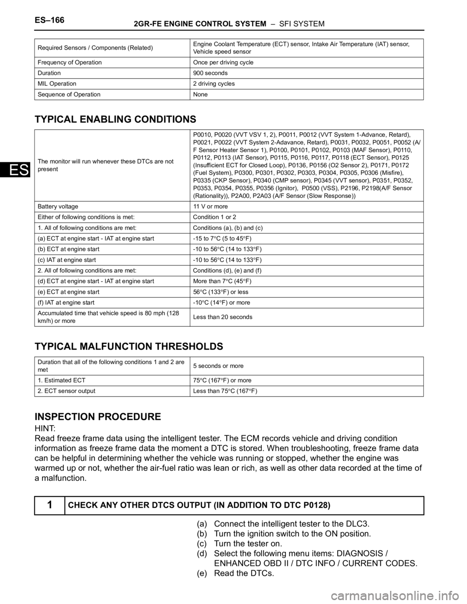
TYPICAL ENABLING CONDITIONS
TYPICAL MALFUNCTION THRESHOLDS
INSPECTION PROCEDURE
HINT:
Read freeze frame data using the intelligent tester. The ECM records vehicle and driving condition
information as freeze frame data the moment a DTC is stored. When troubleshooting, freeze frame data
can be helpful in determining whether the vehicle was running or stopped, whether the engine was
warmed up or not, whether the air-fuel ratio was lean or rich, as well as other data recorded at the time of
a malfunction.
(a) Connect the intelligent tester to the DLC3.
(b) Turn the ignition switch to the ON position.
(c) Turn the tester on.
(d) Select the following menu items: DIAGNOSIS /
ENHANCED OBD II / DTC INFO / CURRENT CODES.
(e) Read the DTCs.
Required Sensors / Components (Related)Engine Coolant Temperature (ECT) sensor, Intake Air Temperature (IAT) sensor,
Vehicle speed sensor
Frequency of Operation Once per driving cycle
Duration 900 seconds
MIL Operation 2 driving cycles
Sequence of Operation None
The monitor will run whenever these DTCs are not
presentP0010, P0020 (VVT VSV 1, 2), P0011, P0012 (VVT System 1-Advance, Retard),
P0021, P0022 (VVT System 2-Adavance, Retard), P0031, P0032, P0051, P0052 (A/
F Sensor Heater Sensor 1), P0100, P0101, P0102, P0103 (MAF Sensor), P0110,
P0112, P0113 (IAT Sensor), P0115, P0116, P0117, P0118 (ECT Sensor), P0125
(Insufficient ECT for Closed Loop), P0136, P0156 (O2 Sensor 2), P0171, P0172
(Fuel System), P0300, P0301, P0302, P0303, P0304, P0305, P0306 (Misfire),
P0335 (CKP Sensor), P0340 (CMP sensor), P0345 (VVT sensor), P0351, P0352,
P0353, P0354, P0355, P0356 (Ignitor), P0500 (VSS), P2196, P2198(A/F Sensor
(Rationality)), P2A00, P2A03 (A/F Sensor (Slow Response))
Battery voltage 11 V or more
Either of following conditions is met: Condition 1 or 2
1. All of following conditions are met: Conditions (a), (b) and (c)
(a) ECT at engine start - IAT at engine start -15 to 7
C (5 to 45F)
(b) ECT at engine start -10 to 56
C (14 to 133F)
(c) IAT at engine start -10 to 56
C (14 to 133F)
2. All of following conditions are met: Conditions (d), (e) and (f)
(d) ECT at engine start - IAT at engine start More than 7
C (45F)
(e) ECT at engine start 56
C (133F) or less
(f) IAT at engine start -10
C (14F) or more
Accumulated time that vehicle speed is 80 mph (128
km/h) or moreLess than 20 seconds
Duration that all of the following conditions 1 and 2 are
met5 seconds or more
1. Estimated ECT 75
C (167F) or more
2. ECT sensor output Less than 75
C (167F)
1CHECK ANY OTHER DTCS OUTPUT (IN ADDITION TO DTC P0128)
Page 478 of 3000

ES–1722GR-FE ENGINE CONTROL SYSTEM – SFI SYSTEM
ES
High or Low Impedance of Heated Oxygen (HO2) Sensor (DTCs P0136 and P0156 or P0137 and
P0157)
During normal air-fuel ratio feedback control, there are small variations in the exhaust gas oxygen
concentration. In order to continuously monitor the slight variation of the HO2 sensor signal while the
engine is running, the impedance* of the sensor is measured by the ECM. The ECM determines that there
is a malfunction in the sensor when the measured impedance deviates from the standard range.
*: The effective resistance in an alternating current electrical circuit.
HINT:
• The impedance cannot be measured using an ohmmeter.
• DTCs P0136 and P0156 indicate the deterioration of the HO2 sensor. The ECM sets the DTCs by
calculating the impedance of the sensor when the typical enabling conditions are satisfied (1 driving
cycle).
• DTCs P0137 and P0157 indicate an open or short circuit in the HO2 sensor (1 driving cycle). The ECM
sets the DTCs when the impedance of the sensor exceeds the threshold 15 k
.
MONITOR STRATEGY
Related DTCsP0136: Heated oxygen sensor output voltage (Output voltage) (bank 1)
P0136: Heated oxygen sensor impedance (Low) (bank 1)
P0137: Heated oxygen sensor output voltage (Low voltage) (bank 1)
P0137: Heated oxygen sensor impedance (High) (bank 1)
P0138: Heated oxygen sensor output voltage (High voltage) (bank 1)
P0138: Heated oxygen sensor output voltage (Extremely high) (bank 1)
P0156: Heated oxygen sensor output voltage (Output voltage) (bank 2)
P0156: Heated oxygen sensor impedance (Low) (bank 2)
P0157: Heated oxygen sensor output voltage (Low voltage) (bank 2)
P0157: Heated oxygen sensor impedance (High) (bank 2)
P0158: Heated oxygen sensor output voltage (High voltage) (bank 2)
P0158: Heated oxygen sensor impedance (Extremely high) (bank 2)
Required Sensors / Components (Main) Heated oxygen sensor
Required Sensors / Components (Related)Crankshaft position sensor, engine coolant temperature sensor, mass air flow meter
and throttle position sensor
Frequency of OperationOnce per driving cycle: Active air-fuel ratio control detection
Continuous: Others
Duration20 seconds: Heated oxygen sensor output (Output voltage, High voltage, Low
voltage)
30 seconds: Heated oxygen sensor impedance (Low)
90 second.: Heated oxygen sensor impedance (High)
10 seconds: Heated oxygen sensor impedance (Extremely high)
MIL Operation 2 driving cycles
Sequence of Operation None
A076841E14
Page 479 of 3000
2GR-FE ENGINE CONTROL SYSTEM – SFI SYSTEMES–173
ES
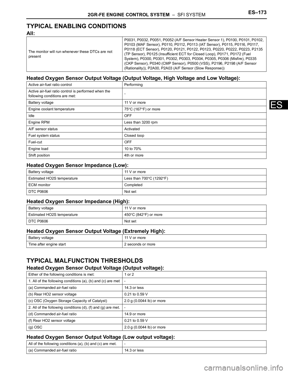
TYPICAL ENABLING CONDITIONS
All:
Heated Oxygen Sensor Output Voltage (Output Voltage, High Voltage and Low Voltage):
Heated Oxygen Sensor Impedance (Low):
Heated Oxygen Sensor Impedance (High):
Heated Oxygen Sensor Output Voltage (Extremely High):
TYPICAL MALFUNCTION THRESHOLDS
Heated Oxygen Sensor Output Voltage (Output voltage):
Heated Oxygen Sensor Output Voltage (Low output voltage):
The monitor will run whenever these DTCs are not
presentP0031, P0032, P0051, P0052 (A/F Sensor Heater Sensor 1), P0100, P0101, P0102,
P0103 (MAF Sensor), P0110, P0112, P0113 (IAT Sensor), P0115, P0116, P0117,
P0118 (ECT Sensor), P0120, P0121, P0122, P0123, P0220, P0222, P0223, P2135
(TP Sensor), P0125 (Insufficient ECT for Closed Loop), P0171, P0172 (Fuel
System), P0300, P0301, P0302, P0303, P0304, P0305, P0306 (Misfire), P0335
(CKP Sensor), P0340 (CMP Sensor), P0500 (VSS), P2196, P2198 (A/F Sensor
(Rationality)), P2A00, P2A03 (A/F Sensor (Slow Response))
Active air-fuel ratio control Performing
Active air-fuel ratio control is performed when the
following conditions are met:-
Battery voltage 11 V or more
Engine coolant temperature 75
C (167F) or more
Idle OFF
Engine RPM Less than 3200 rpm
A/F sensor status Activated
Fuel system status Closed loop
Fuel-cut OFF
Engine load 10 to 70%
Shift position 4th or more
Battery voltage 11 V or more
Estimated HO2S temperature Less than 700
C (1292F)
ECM monitor Completed
DTC P0606 Not set
Battery voltage 11 V or more
Estimated HO2S temperature 450
C (842F) or more
DTC P0606 Not set
Battery voltage 11 V or more
Time after engine start 2 seconds or more
Either of the following conditions is met: 1 or 2
1. All of the following conditions (a), (b) and (c) are met -
(a) Commanded air-fuel ratio 14.3 or less
(b) Rear HO2 sensor voltage 0.21 to 0.59 V
(c) OSC (Oxygen Storage Capacity of Catalyst) 2.0 g (0.0044 lb) or more
2. All of the following conditions (d), (f) and (g) are met. -
(d) Commanded air-fuel ratio 14.9 or more
(f) Rear HO2 sensor voltage 0.21 to 0.59 V
(g) OSC 2.0 g (0.0044 lb) or more
All of the following conditions (a), (b) and (c) are met. -
(a) Commanded air-fuel ratio 14.3 or less
Page 494 of 3000
ES–1882GR-FE ENGINE CONTROL SYSTEM – SFI SYSTEM
ES
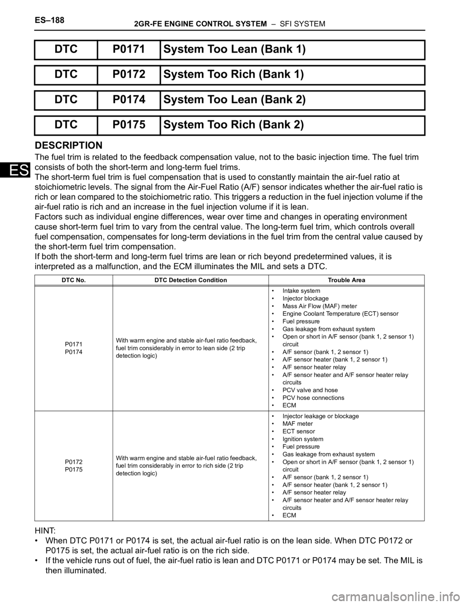
DESCRIPTION
The fuel trim is related to the feedback compensation value, not to the basic injection time. The fuel trim
consists of both the short-term and long-term fuel trims.
The short-term fuel trim is fuel compensation that is used to constantly maintain the air-fuel ratio at
stoichiometric levels. The signal from the Air-Fuel Ratio (A/F) sensor indicates whether the air-fuel ratio is
rich or lean compared to the stoichiometric ratio. This triggers a reduction in the fuel injection volume if the
air-fuel ratio is rich and an increase in the fuel injection volume if it is lean.
Factors such as individual engine differences, wear over time and changes in operating environment
cause short-term fuel trim to vary from the central value. The long-term fuel trim, which controls overall
fuel compensation, compensates for long-term deviations in the fuel trim from the central value caused by
the short-term fuel trim compensation.
If both the short-term and long-term fuel trims are lean or rich beyond predetermined values, it is
interpreted as a malfunction, and the ECM illuminates the MIL and sets a DTC.
HINT:
• When DTC P0171 or P0174 is set, the actual air-fuel ratio is on the lean side. When DTC P0172 or
P0175 is set, the actual air-fuel ratio is on the rich side.
• If the vehicle runs out of fuel, the air-fuel ratio is lean and DTC P0171 or P0174 may be set. The MIL is
then illuminated.
DTC P0171 System Too Lean (Bank 1)
DTC P0172 System Too Rich (Bank 1)
DTC P0174 System Too Lean (Bank 2)
DTC P0175 System Too Rich (Bank 2)
DTC No. DTC Detection Condition Trouble Area
P0171
P0174With warm engine and stable air-fuel ratio feedback,
fuel trim considerably in error to lean side (2 trip
detection logic)• Intake system
• Injector blockage
• Mass Air Flow (MAF) meter
• Engine Coolant Temperature (ECT) sensor
• Fuel pressure
• Gas leakage from exhaust system
• Open or short in A/F sensor (bank 1, 2 sensor 1)
circuit
• A/F sensor (bank 1, 2 sensor 1)
• A/F sensor heater (bank 1, 2 sensor 1)
• A/F sensor heater relay
• A/F sensor heater and A/F sensor heater relay
circuits
• PCV valve and hose
• PCV hose connections
•ECM
P0172
P0175With warm engine and stable air-fuel ratio feedback,
fuel trim considerably in error to rich side (2 trip
detection logic)• Injector leakage or blockage
• MAF meter
• ECT sensor
• Ignition system
• Fuel pressure
• Gas leakage from exhaust system
• Open or short in A/F sensor (bank 1, 2 sensor 1)
circuit
• A/F sensor (bank 1, 2 sensor 1)
• A/F sensor heater (bank 1, 2 sensor 1)
• A/F sensor heater relay
• A/F sensor heater and A/F sensor heater relay
circuits
•ECM
Page 495 of 3000

2GR-FE ENGINE CONTROL SYSTEM – SFI SYSTEMES–189
ES
• When the total of the short-term and long-term fuel trim values is within the malfunction threshold (and
the engine coolant temperature is more than 75
C [167F]), the system is functioning normally.
MONITOR DESCRIPTION
Under closed-loop fuel control, fuel injection volumes that deviate from those estimated by the ECM
cause changes in the long-term fuel trim compensation value. The long-term fuel trim is adjusted when
there are persistent deviations in the short-term fuel trim values. Deviations from the ECM's estimated fuel
injection volumes also affect the average fuel trim learning value, which is a combination of the average
short-term fuel trim (fuel feedback compensation value) and the average long-term fuel trim (learning
value of the air-fuel ratio). If the average fuel trim learning value exceeds the malfunction thresholds, the
ECM interprets this as a fault in the fuel system and sets a DTC.
Example:
The average fuel trim learning value is more than +35% or less than -35%, the ECM interprets this as a
fuel system malfunction.
MONITOR STRATEGY
Related DTCsP0171: Fuel trim Lean (Bank 1)
P0172: Fuel trim Rich (Bank 1)
P0174: Fuel trim Lean (Bank 2)
P0175: Fuel trim Rich (Bank 2)
Required Sensors / Components (Main) Fuel system
Required Sensors / Components (Related) A/F sensor, Mass air flow meter, Crankshaft position sensor
Frequency of Operation Continuous
Duration Less than 10 seconds
MIL Operation 2 driving cycles
Sequence of Operation None
A082386E30
Page 499 of 3000
2GR-FE ENGINE CONTROL SYSTEM – SFI SYSTEMES–193
ES
OK
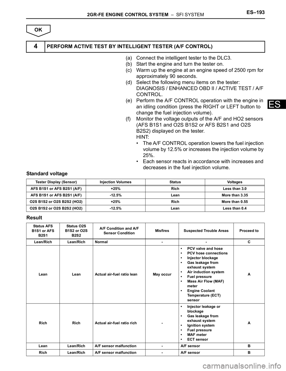
(a) Connect the intelligent tester to the DLC3.
(b) Start the engine and turn the tester on.
(c) Warm up the engine at an engine speed of 2500 rpm for
approximately 90 seconds.
(d) Select the following menu items on the tester:
DIAGNOSIS / ENHANCED OBD II / ACTIVE TEST / A/F
CONTROL.
(e) Perform the A/F CONTROL operation with the engine in
an idling condition (press the RIGHT or LEFT button to
change the fuel injection volume).
(f) Monitor the voltage outputs of the A/F and HO2 sensors
(AFS B1S1 and O2S B1S2 or AFS B2S1 and O2S
B2S2) displayed on the tester.
HINT:
• The A/F CONTROL operation lowers the fuel injection
volume by 12.5% or increases the injection volume by
25%.
• Each sensor reacts in accordance with increases and
decreases in the fuel injection volume.
Standard voltage
Result
4PERFORM ACTIVE TEST BY INTELLIGENT TESTER (A/F CONTROL)
Tester Display (Sensor) Injection Volumes Status Voltages
AFS B1S1 or AFS B2S1 (A/F) +25% Rich Less than 3.0
AFS B1S1 or AFS B2S1 (A/F) -12.5% Lean More than 3.35
O2S B1S2 or O2S B2S2 (HO2) +25% Rich More than 0.55
O2S B1S2 or O2S B2S2 (HO2) -12.5% Lean Less than 0.4
Status AFS
B1S1 or AFS
B2S1Status O2S
B1S2 or O2S
B2S2A/F Condition and A/F
Sensor ConditionMisfires Suspected Trouble Areas Proceed to
Lean/Rich Lean/Rich Normal - - C
Lean Lean Actual air-fuel ratio lean May occur• PCV valve and hose
• PCV hose connections
• Injector blockage
• Gas leakage from
exhaust system
• Air induction system
• Fuel pressure
• Mass Air Flow (MAF)
meter
• Engine Coolant
Temperature (ECT)
sensorA
Rich Rich Actual air-fuel ratio rich -• Injector leakage or
blockage
• Gas leakage from
exhaust system
• Ignition system
• Fuel pressure
• MAF meter
• ECT sensorA
Lean Lean/Rich A/F sensor malfunction - A/F sensor B
Rich Lean/Rich A/F sensor malfunction - A/F sensor B
Page 500 of 3000
ES–1942GR-FE ENGINE CONTROL SYSTEM – SFI SYSTEM
ES
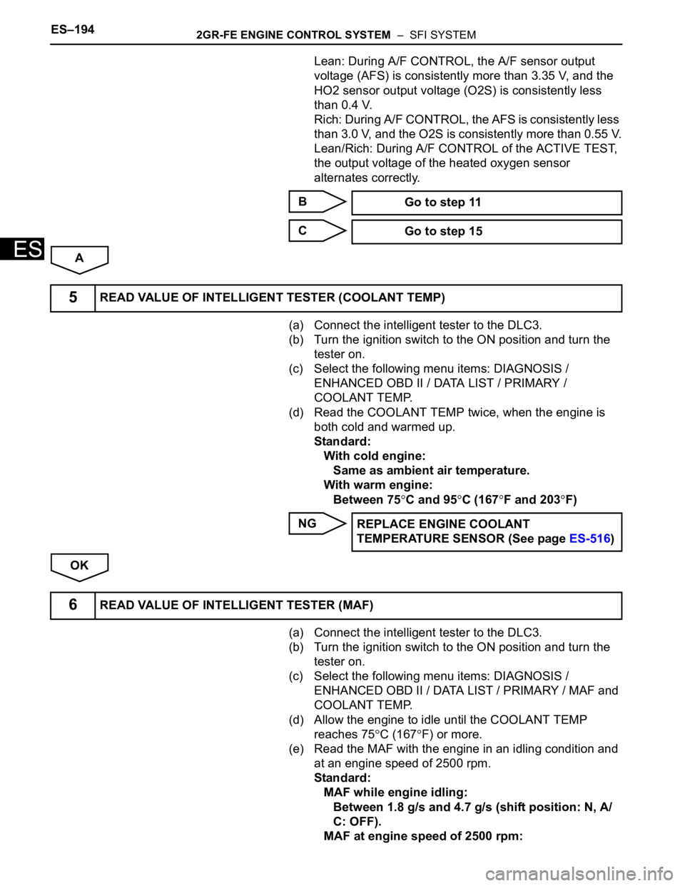
Lean: During A/F CONTROL, the A/F sensor output
voltage (AFS) is consistently more than 3.35 V, and the
HO2 sensor output voltage (O2S) is consistently less
than 0.4 V.
Rich: During A/F CONTROL, the AFS is consistently less
than 3.0 V, and the O2S is consistently more than 0.55 V.
Lean/Rich: During A/F CONTROL of the ACTIVE TEST,
the output voltage of the heated oxygen sensor
alternates correctly.
B
C
A
(a) Connect the intelligent tester to the DLC3.
(b) Turn the ignition switch to the ON position and turn the
tester on.
(c) Select the following menu items: DIAGNOSIS /
ENHANCED OBD II / DATA LIST / PRIMARY /
COOLANT TEMP.
(d) Read the COOLANT TEMP twice, when the engine is
both cold and warmed up.
Standard:
With cold engine:
Same as ambient air temperature.
With warm engine:
Between 75
C and 95C (167F and 203F)
NG
OK
(a) Connect the intelligent tester to the DLC3.
(b) Turn the ignition switch to the ON position and turn the
tester on.
(c) Select the following menu items: DIAGNOSIS /
ENHANCED OBD II / DATA LIST / PRIMARY / MAF and
COOLANT TEMP.
(d) Allow the engine to idle until the COOLANT TEMP
reaches 75
C (167F) or more.
(e) Read the MAF with the engine in an idling condition and
at an engine speed of 2500 rpm.
Standard:
MAF while engine idling:
Between 1.8 g/s and 4.7 g/s (shift position: N, A/
C: OFF).
MAF at engine speed of 2500 rpm: Go to step 11
Go to step 15
5READ VALUE OF INTELLIGENT TESTER (COOLANT TEMP)
REPLACE ENGINE COOLANT
TEMPERATURE SENSOR (See page ES-516)
6READ VALUE OF INTELLIGENT TESTER (MAF)
Page 510 of 3000
ES–2042GR-FE ENGINE CONTROL SYSTEM – SFI SYSTEM
ES
DESCRIPTION
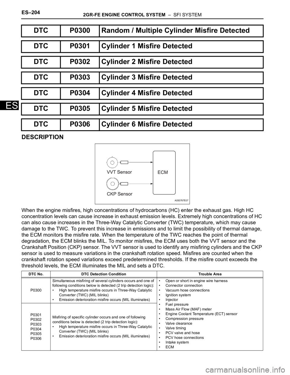
When the engine misfires, high concentrations of hydrocarbons (HC) enter the exhaust gas. High HC
concentration levels can cause increase in exhaust emission levels. Extremely high concentrations of HC
can also cause increases in the Three-Way Catalytic Converter (TWC) temperature, which may cause
damage to the TWC. To prevent this increase in emissions and to limit the possibility of thermal damage,
the ECM monitors the misfire rate. When the temperature of the TWC reaches the point of thermal
degradation, the ECM blinks the MIL. To monitor misfires, the ECM uses both the VVT sensor and the
Crankshaft Position (CKP) sensor. The VVT sensor is used to identify any misfiring cylinders and the CKP
sensor is used to measure variations in the crankshaft rotation speed. Misfires are counted when the
crankshaft rotation speed variations exceed predetermined thresholds. If the misfire count exceeds the
threshold levels, the ECM illuminates the MIL and sets a DTC.
DTC P0300 Random / Multiple Cylinder Misfire Detected
DTC P0301 Cylinder 1 Misfire Detected
DTC P0302 Cylinder 2 Misfire Detected
DTC P0303 Cylinder 3 Misfire Detected
DTC P0304 Cylinder 4 Misfire Detected
DTC P0305 Cylinder 5 Misfire Detected
DTC P0306 Cylinder 6 Misfire Detected
DTC No. DTC Detection Condition Trouble Area
P0300Simultaneous misfiring of several cylinders occurs and one of
following conditions below is detected (2 trip detection logic):
• High temperature misfire occurs in Three-Way Catalytic
Converter (TWC) (MIL blinks)
• Emission deterioration misfire occurs (MIL illuminates)• Open or short in engine wire harness
• Connector connection
• Vacuum hose connections
• Ignition system
• Injector
• Fuel pressure
• Mass Air Flow (MAF) meter
• Engine Coolant Temperature (ECT) sensor
• Compression pressure
• Valve clearance
• Valve timing
• PCV valve and hose
• PCV hose connections
• Intake system
•ECM P0301
P0302
P0303
P0304
P0305
P0306Misfiring of specific cylinder occurs and one of following
conditions below is detected (2 trip detection logic):
• High temperature misfire occurs in Three-Way Catalytic
Converter (TWC) (MIL blinks)
• Emission deterioration misfire occurs (MIL illuminates)
A093767E07
Page 511 of 3000
2GR-FE ENGINE CONTROL SYSTEM – SFI SYSTEMES–205
ES
When multiple DTCs for misfiring cylinders are set, but DTC P0300 is not set, it indicates that misfires
have been detected in different cylinders at different times. DTC P0300 is only set when several misfiring
cylinders are detected at the same time.
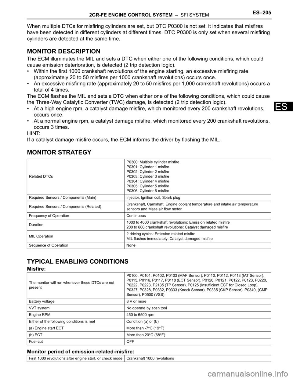
MONITOR DESCRIPTION
The ECM illuminates the MIL and sets a DTC when either one of the following conditions, which could
cause emission deterioration, is detected (2 trip detection logic).
• Within the first 1000 crankshaft revolutions of the engine starting, an excessive misfiring rate
(approximately 20 to 50 misfires per 1000 crankshaft revolutions) occurs once.
• An excessive misfiring rate (approximately 20 to 50 misfires per 1,000 crankshaft revolutions) occurs a
total of 4 times.
The ECM flashes the MIL and sets a DTC when either one of the following conditions, which could cause
the Three-Way Catalytic Converter (TWC) damage, is detected (2 trip detection logic).
• At a high engine rpm, a catalyst damage misfire, which monitored every 200 crankshaft revolutions,
occurs once.
• At a normal engine rpm, a catalyst damage misfire, which monitored every 200 crankshaft revolutions,
occurs 3 times.
HINT:
If a catalyst damage misfire occurs, the ECM informs the driver by flashing the MIL.
MONITOR STRATEGY
TYPICAL ENABLING CONDITIONS
Misfire:
Monitor period of emission-related-misfire:
Related DTCsP0300: Multiple cylinder misfire
P0301: Cylinder 1 misfire
P0302: Cylinder 2 misfire
P0303: Cylinder 3 misfire
P0304: Cylinder 4 misfire
P0305: Cylinder 5 misfire
P0306: Cylinder 6 misfire
Required Sensors / Components (Main) Injector, Ignition coil, Spark plug
Required Sensors / Components (Related)Crankshaft, Camshaft, Engine coolant temperature and intake air temperature
sensors and Mass air flow meter
Frequency of Operation Continuous
Duration1000 to 4000 crankshaft revolutions: Emission related misfire
200 to 600 crankshaft revolutions: Catalyst damaged misfire
MIL Operation2 driving cycles: Emission related misfire
MIL flashes immediately: Catalyst damaged misfire
Sequence of Operation None
The monitor will run whenever these DTCs are not
presentP0100, P0101, P0102, P0103 (MAF Sensor), P0110, P0112, P0113 (IAT Sensor),
P0115, P0116, P0117, P0118 (ECT Sensor), P0120, P0121, P0122, P0123, P0220,
P0222, P0223, P2135 (TP Sensor), P0125 (Insufficient ECT for Closed Loop),
P0327, P0328, P0332, P0333 (Knock Sensor), P0335 (CKP Sensor), P0340, (CMP
Sensor), P0500 (VSS)
Battery voltage 8 V or more
VVT system No operate by scan tool
Engine RPM 450 to 6500 rpm
Either of the following conditions is met Condition (a) or (b)
(a) Engine start ECT More than -7
C (19F)
(b) ECT More than 20
C (68F)
Fuel-cut OFF
First 1000 revolutions after engine start, or check mode Crankshaft 1000 revolutions
Page 514 of 3000
ES–2082GR-FE ENGINE CONTROL SYSTEM – SFI SYSTEM
ES
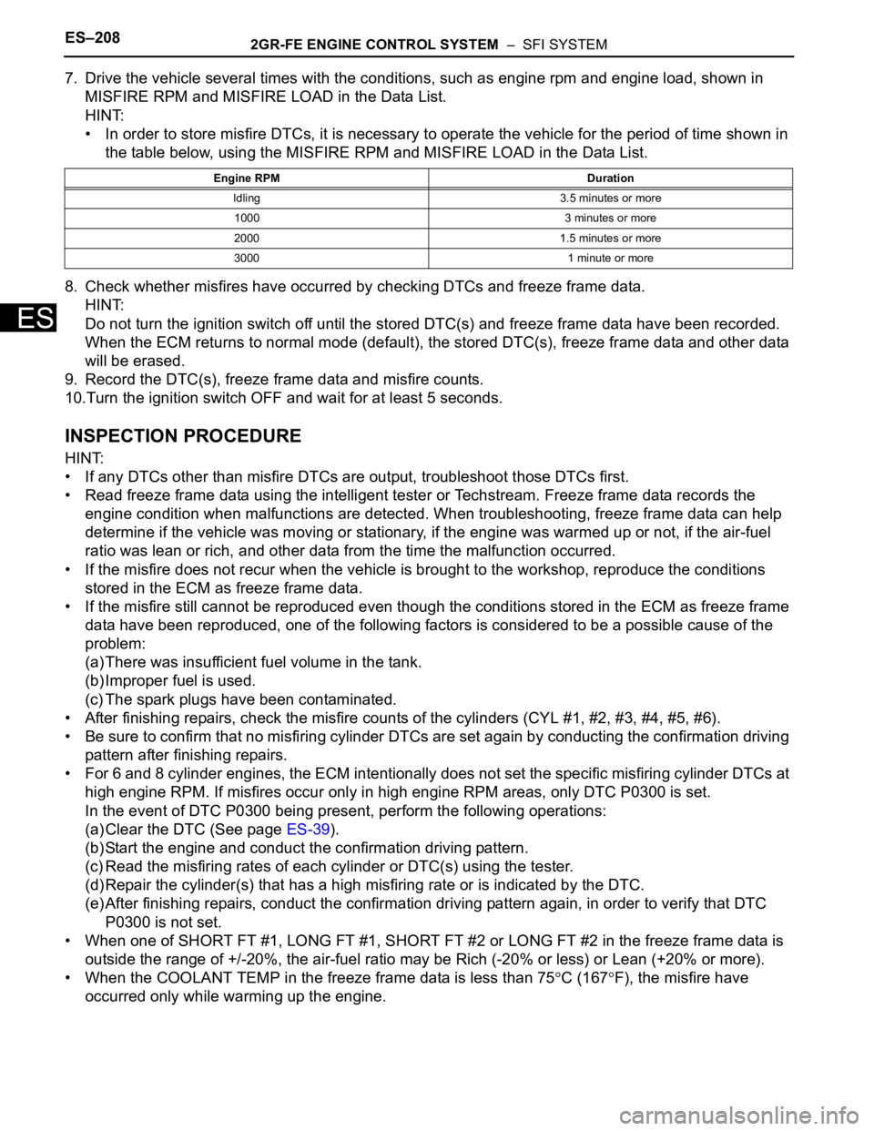
7. Drive the vehicle several times with the conditions, such as engine rpm and engine load, shown in
MISFIRE RPM and MISFIRE LOAD in the Data List.
HINT:
• In order to store misfire DTCs, it is necessary to operate the vehicle for the period of time shown in
the table below, using the MISFIRE RPM and MISFIRE LOAD in the Data List.
8. Check whether misfires have occurred by checking DTCs and freeze frame data.
HINT:
Do not turn the ignition switch off until the stored DTC(s) and freeze frame data have been recorded.
When the ECM returns to normal mode (default), the stored DTC(s), freeze frame data and other data
will be erased.
9. Record the DTC(s), freeze frame data and misfire counts.
10.Turn the ignition switch OFF and wait for at least 5 seconds.
INSPECTION PROCEDURE
HINT:
• If any DTCs other than misfire DTCs are output, troubleshoot those DTCs first.
• Read freeze frame data using the intelligent tester or Techstream. Freeze frame data records the
engine condition when malfunctions are detected. When troubleshooting, freeze frame data can help
determine if the vehicle was moving or stationary, if the engine was warmed up or not, if the air-fuel
ratio was lean or rich, and other data from the time the malfunction occurred.
• If the misfire does not recur when the vehicle is brought to the workshop, reproduce the conditions
stored in the ECM as freeze frame data.
• If the misfire still cannot be reproduced even though the conditions stored in the ECM as freeze frame
data have been reproduced, one of the following factors is considered to be a possible cause of the
problem:
(a) There was insufficient fuel volume in the tank.
(b) Improper fuel is used.
(c) The spark plugs have been contaminated.
• After finishing repairs, check the misfire counts of the cylinders (CYL #1, #2, #3, #4, #5, #6).
• Be sure to confirm that no misfiring cylinder DTCs are set again by conducting the confirmation driving
pattern after finishing repairs.
• For 6 and 8 cylinder engines, the ECM intentionally does not set the specific misfiring cylinder DTCs at
high engine RPM. If misfires occur only in high engine RPM areas, only DTC P0300 is set.
In the event of DTC P0300 being present, perform the following operations:
(a) Clear the DTC (See page ES-39).
(b) Start the engine and conduct the confirmation driving pattern.
(c) Read the misfiring rates of each cylinder or DTC(s) using the tester.
(d) Repair the cylinder(s) that has a high misfiring rate or is indicated by the DTC.
(e) After finishing repairs, conduct the confirmation driving pattern again, in order to verify that DTC
P0300 is not set.
• When one of SHORT FT #1, LONG FT #1, SHORT FT #2 or LONG FT #2 in the freeze frame data is
outside the range of +/-20%, the air-fuel ratio may be Rich (-20% or less) or Lean (+20% or more).
• When the COOLANT TEMP in the freeze frame data is less than 75
C (167F), the misfire have
occurred only while warming up the engine.
Engine RPM Duration
Idling 3.5 minutes or more
1000 3 minutes or more
2000 1.5 minutes or more
3000 1 minute or more