Position TOYOTA SIENNA 2007 Service Repair Manual
[x] Cancel search | Manufacturer: TOYOTA, Model Year: 2007, Model line: SIENNA, Model: TOYOTA SIENNA 2007Pages: 3000, PDF Size: 52.26 MB
Page 2903 of 3000
AC–14AIR CONDITIONING – AIR CONDITIONING SYSTEM (for Automatic Air Conditioning Sys-
tem)
AC
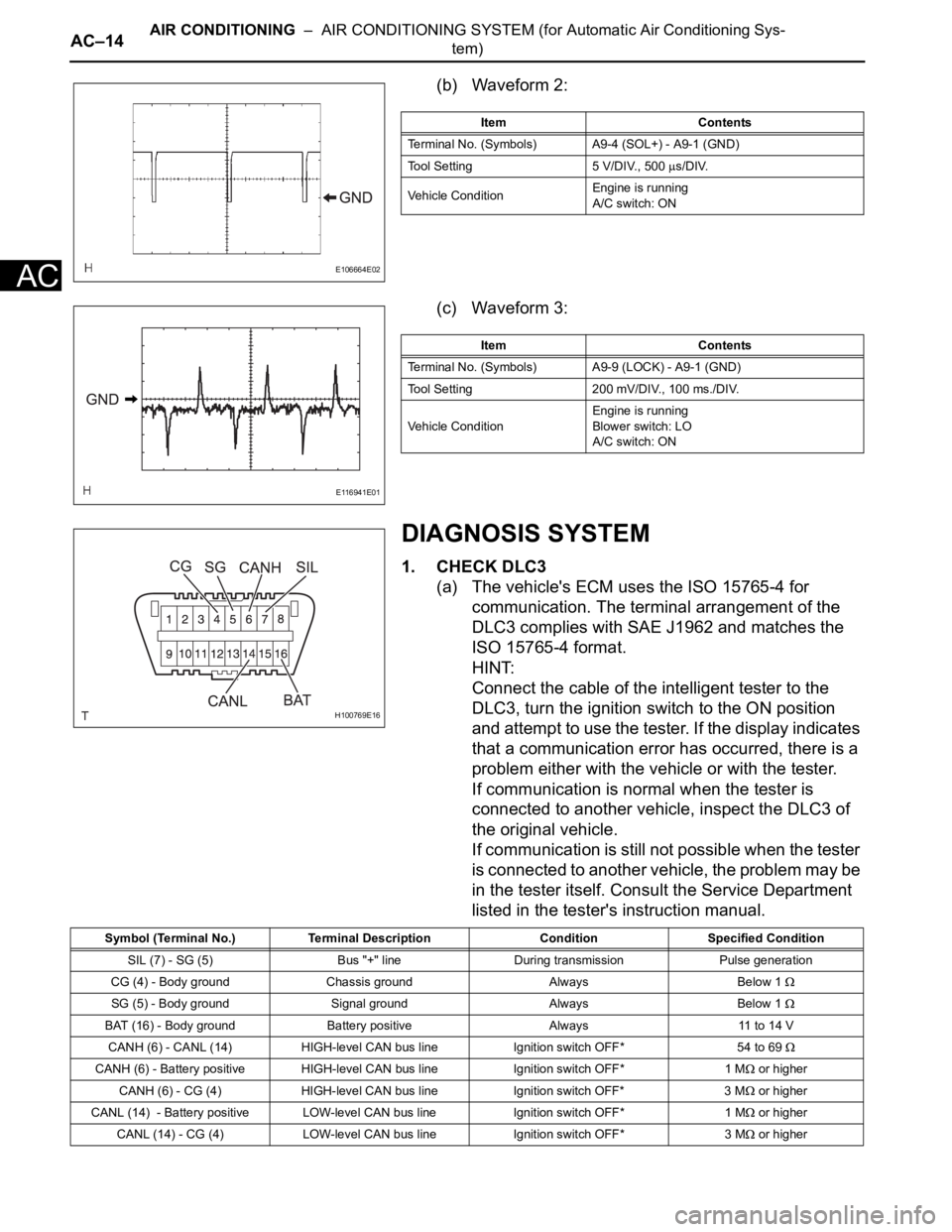
(b) Waveform 2:
(c) Waveform 3:
DIAGNOSIS SYSTEM
1. CHECK DLC3
(a) The vehicle's ECM uses the ISO 15765-4 for
communication. The terminal arrangement of the
DLC3 complies with SAE J1962 and matches the
ISO 15765-4 format.
HINT:
Connect the cable of the intelligent tester to the
DLC3, turn the ignition switch to the ON position
and attempt to use the tester. If the display indicates
that a communication error has occurred, there is a
problem either with the vehicle or with the tester.
If communication is normal when the tester is
connected to another vehicle, inspect the DLC3 of
the original vehicle.
If communication is still not possible when the tester
is connected to another vehicle, the problem may be
in the tester itself. Consult the Service Department
listed in the tester's instruction manual.
E106664E02
Item Contents
Terminal No. (Symbols) A9-4 (SOL+) - A9-1 (GND)
Tool Setting 5 V/DIV., 500
s/DIV.
Vehicle ConditionEngine is running
A/C switch: ON
E116941E01
Item Contents
Terminal No. (Symbols) A9-9 (LOCK) - A9-1 (GND)
Tool Setting 200 mV/DIV., 100 ms./DIV.
Vehicle ConditionEngine is running
Blower switch: LO
A/C switch: ON
H100769E16
Symbol (Terminal No.) Terminal Description Condition Specified Condition
SIL (7) - SG (5) Bus "+" line During transmission Pulse generation
CG (4) - Body ground Chassis ground Always Below 1
SG (5) - Body ground Signal ground Always Below 1
BAT (16) - Body ground Battery positive Always 11 to 14 V
CANH (6) - CANL (14) HIGH-level CAN bus line Ignition switch OFF*54 to 69
CANH (6) - Battery positive HIGH-level CAN bus line Ignition switch OFF* 1 M or higher
CANH (6) - CG (4) HIGH-level CAN bus line Ignition switch OFF* 3 M
or higher
CANL (14) - Battery positive LOW-level CAN bus line Ignition switch OFF* 1 M
or higher
CANL (14) - CG (4) LOW-level CAN bus line Ignition switch OFF* 3 M
or higher
Page 2905 of 3000

AC–164AIR CONDITIONING – AIR CONDITIONING SYSTEM (for Manual Air Conditioning System)
AC
TERMINALS OF ECU
1. A/C AMPLIFIER
HINT:
Check from the rear of the connector while it is
connected to the A/C amplifier.
E145189E02
Terminal No.
(Symbols)Wiring Color Description Condition Specified Condition
A9-1 (S5) - A9-26 (SG) BR-R - LG-RPower supply for air mix
control damper position
sensorIgnition switch: ON 4.5 to 5.5 V
A9-3 (TE) - A9-7 (SG-4) G-B - YA/C evaporator
temperature sensor signalIgnition switch: ON
Evaporator temperature:
0
C (32F)2.0 to 2.4 V
A9-3 (TE) - A9-7 (SG-4) G-B - YA/C evaporator
temperature sensor signalIgnition switch: ON
Evaporator temperature:
15
C (59F)1.4 to 1.8 V
A9-4 (MPX+) - Body
groundV - Body groundMultiplex communication
systemMultiplex communication
circuitPulse generation
A9-5 (MPX-) - Body
groundR-L - Body groundMultiplex communication
systemMultiplex communication
circuitPulse generation
A9-6 (GND) - Body ground W-B - Body groundGround for main power
supplyAlways Below 1 V
A9-7 (SG-4) - Body
groundY - Body groundGround for A/C evaporator
temperature sensorAlways Below 1 V
A9-8 (FTIN) - A9-6 (GND) B-O - W-BMode control switch
operation signalIgnition switch: ON
Rear mode control switch
(FOOT): OFF4.5 to 5.5 V
A9-8 (FTIN) - A9-6 (GND) B-O - W-BMode control switch
operation signalIgnition switch: ON
Rear mode control switch
(FOOT): ONBelow 1 V
A9-9 (BLIN) - A9-6 (GND) W - W-BMode control switch
operation signalIgnition switch: ON
Rear mode control switch
(B/L): OFF4.5 to 5.5 V
A9-9 (BLIN) - A9-6 (GND) W - W-BMode control switch
operation signalIgnition switch: ON
Rear mode control switch
(B/L): ONBelow 1 V
A9-10 (FCIN) - A9-6
(GND)BR-B - W-BMode control switch
operation signalIgnition switch: ON
Rear mode control switch
(FACE): OFF4.5 to 5.5 V
A9-10 (FCIN) - A9-6
(GND)BR-B - W-BMode control switch
operation signalIgnition switch: ON
Rear mode control switch
(FACE): ONBelow 1 V
A9-11 (RDSW) - A9-6
(GND)Y- G - W - BRear defogger operation
signalIgnition switch: ON
REAR DEF switch: OFF4.5 to 5.5 V
A9-11 (RDSW) - A9-6
(GND)Y- G - W - BRear defogger operation
signalIgnition switch: ON
REAR DEF switch: ONBelow 1 V
Page 2906 of 3000

AIR CONDITIONING – AIR CONDITIONING SYSTEM (for Manual Air Conditioning System)AC–165
AC
A9-12 (SOL+) - A9-6
(GND)W-L - W-BA/C compressor operation
signalEngine is runningA/C
switch: ON
Front blower control dial:
LOPulse generation
(See waveform 1)
A9-13 (AOD) - A9-6
(GND)G-O - W-BAir outlet control servo
motor operation signalIgnition switch: ON
Front mode control dial:
FOOTBelow 1 V
A9-13 (AOD) - A9-6
(GND)G-O - W-BAir outlet control servo
motor operation signalIgnition switch: ON
Front mode control dial:
DEF11 to 14 V
A9-14 (AOF) - A9-6 (GND) L-O - W-BAir outlet control servo
motor operation signalIgnition switch: ON
Front mode control dial:
DEFBelow 1 V
A9-14 (AOF) - A9-6 (GND) L-O - W-BAir outlet control servo
motor operation signalIgnition switch: ON
Front mode control dial:
FOOT11 to 14 V
A9-15 (FOOT) - A9-6
(GND)G-Y - W-BRear air outlet control
servo motor operation
signalIgnition switch: ON
Rear mode control switch
(FOOT): OFFBelow 1 V
A9-15 (FOOT) - A9-6
(GND)G-Y - W-BRear air outlet control
servo motor operation
signalIgnition switch: ON
Rear mode control switch
(FOOT): ON11 to 14 V
A9-16 (FACE) - A9-6
(GND)LG-B - W-BRear air outlet control
servo motor operation
signalIgnition switch: ON
Rear mode control switch
(FACE): OFFBelow 1 V
A9-16 (FACE) - A9-6
(GND)LG-B - W-BRear air outlet control
servo motor operation
signalIgnition switch: ON
Rear mode control switch
(FACE): ON11 t o 1 4 V
A9-17 (+B) - A9-6 (GND) W-L - W-B Power source (Battery) Always 11 to 14 V
A9-18 (IG) - A9-6 (GND) R-Y - W-B Power source (IG) Ignition switch: OFF Below 1 V
A9-18 (IG) - A9-6 (GND) R-Y - W-B Power source (IG) Ignition switch: ON 11 to 14 V
A9-19 (MHH) - A9-6
(GND)V- Y - W- BRear air mix control servo
motor operation signalIgnition switch: ON
Rear temperature control
dial: MAX COLDBelow 1 V
A9-19 (MHH) - A9-6
(GND)V- Y - W- BRear air mix control servo
motor operation signalIgnition switch: ON
Rear temperature control
dial: MAX HOT11 t o 1 4 V
A9-20 (MCH) - A9-6
(GND)GR-L - W-BRear air mix control servo
motor operation signalIgnition switch: ON
Rear temperature control
dial: MAX HOTBelow 1 V
A9-20 (MCH) - A9-6
(GND)GR-L - W-BRear air mix control servo
motor operation signalIgnition switch: ON
Rear temperature control
dial: MAX COLD11 to 14 V
A9-21 (S5) - A9-6 (GND) B-W - W-BPower supply for mode
control switchIgnition switch: ON 4.5 to 5.5 V
A9-22 (S5-1) - A9-27 (SG-
1)P-L - GR-LPower supply for air outlet
control damper position
sensorIgnition switch: ON 4.5 to 5.5 V
A9-23 (S5) - A9-6 (GND) P-L - W-BPower supply for rear air
outlet control damper
position sensorIgnition switch: ON 4.5 to 5.5 V
A9-24 (TSET) - A9-6
(GND)R-G - W-BRear temperature control
dial operation signalIgnition switch: ON
Rear temperature control
dial: ON0 to 5 V
A9-25 (BSET) - A9-6
(GND)GR-G - W-BRear blower control dial
operation signalIgnition switch: ON
Rear blower control dial:
ON0 to 5 V
A9-26 (SG) - Body ground LG-R - Body groundGround for air mix control
damper position sensorAlways Below 1 V Terminal No.
(Symbols)Wiring Color Description Condition Specified Condition
Page 2907 of 3000

AC–166AIR CONDITIONING – AIR CONDITIONING SYSTEM (for Manual Air Conditioning System)
AC
A9-27 (SG-1) - Body
groundGR-L - Body groundGround for air outlet
control damper position
sensorAlways Below 1 V
A9-28 (SG) - Body ground V-W - Body groundGround for rear A/C
control assemblyAlways Below 1 V
A9-29 (SG) - Body ground W-R - Body groundGround for rear air outlet
control damper position
sensorAlways Below 1 V
A9-30 (SG-6) - Body
groundW-G - Body groundGround for A/C lock
sensor, A/C pressure
sensor and A/C ambient
temperature sensorAlways Below 1 V
A9-35 (THOT) - A9-6
(GND)L-B - W-BAir mix control servo motor
operation signalIgnition switch: ON
Front temperature control
dial: MAX. COLDBelow 1 V
A9-35 (THOT) - A9-6
(GND)L-B - W-BAir mix control servo motor
operation signalIgnition switch: ON
Front temperature control
dial: MAX. HOT11 to 14 V
A9-36 (TCOL) - A9-6
(GND)P-G - W-BAir mix control servo motor
operation signalIgnition switch: ON
Front temperature control
dial: MAX. HOTBelow 1 V
A9-36 (TCOL) - A9-6
(GND)P-G - W-BAir mix control servo motor
operation signalIgnition switch: ON
Front temperature control
dial: MAX. COLD11 to 14 V
A9-38 (A/CB) - A9-6
(GND)B - W-B Power source (Battery)Ignition switch: ON
Front blower control dial:
OFFBelow 1 V
A9-38 (A/CB) - A9-6
(GND)B - W-B Power source (Battery)Ignition switch: ON
Front blower control dial:
ON11 to 14 V
A9-40 (ACC) - A9-6 (GND) P - W-B Power source (ACC) Ignition switch: OFF Below 1 V
A9-40 (ACC) - A9-6 (GND) P - W-B Power source (ACC) Ignition switch: ACC 11 to 14 V
A10-2 (LOCK) - A9-30
(SG-6)L - W-G A/C lock sensor signalEngine is running
Front blower control dial:
LO
A/C switch: ONPulse generation
(See waveform 2)
A10-6 (BLWC) - A9-6
(GND)L-W - W-BRear blower motor
operation signalIgnition switch: ON
Rear blower control dial:
ON1.7 to 2.0 V
A10-7 (VMC) - A9-6
(GND)P-B - W-BRear blower motor
operation signalIgnition switch: ON
Rear blower control dial:
ON0 to 9 V
A10-9 (TAM) - A9-30 (SG-
6)
B-R - W-GA/C ambient temperature
sensor signalIgnition switch: ON
Ambient temperature:
25C (77F)1.35 to 1.75 V
A10-9 (TAM) - A9-30 (SG-
6)B-R - W-GA/C ambient temperature
sensor signalIgnition switch: ON
Ambient temperature:
40
C (104F)0.85 to 1.25 V
A10-10 (PRE) - A9-30
(SG-6)V - W-GA/C pressure sensor
signalStart engine
Operate A/C system
Refrigerant pressure:
Abnormal pressure (more
than 3140 kPa (32.0 kgf/
cm
2, 455 psi))4.74 V or higher
A10-10 (PRE) - A9-30
(SG-6)V - W-GA/C pressure sensor
signalStart engine
Operate A/C system
Refrigerant pressure:
Abnormal pressure (less
than 196 kPa (2.0 kgf/cm
2,
28 psi))Below 0.76 V Terminal No.
(Symbols)Wiring Color Description Condition Specified Condition
Page 2908 of 3000

AIR CONDITIONING – AIR CONDITIONING SYSTEM (for Manual Air Conditioning System)AC–167
AC
(a) Waveform 1:
A10-10 (PRE) - A9-30
(SG-6)V - W-GA/C pressure sensor
signalStart engine
Operate A/C system
Refrigerant pressure:
Normal pressure (less
than 3140 kPa (32.0 kgf/
cm
2, 455 psi) and more
than 196 kPa (2.0 kgf/cm2,
28 psi))0.76 to 4.74 V
A10-11 (TPO) - A9-27
(SG-1)LG - GR-LAir outlet control damper
position sensor signalIgnition switch: ON
Front mode control dial:
FOOT
DEF1.0 to 4.0 V
A10-12 (TP) - A9-26 (SG) L-R - LG-RAir mix control damper
position sensor signalIgnition switch: ON
Front temperature control
dial: MAX. HOT
MAX.
COLD1.0 to 4.0 V
A10-19 (REC) - A9-6
(GND)GR-R - W-BAir inlet control servo
motor operation signalIgnition switch: ON
R/F switch: FRESHBelow 1 V
A10-19 (REC) - A9-6
(GND)GR-R - W-BAir inlet control servo
motor operation signalIgnition switch: ON
R/F switch:
RECIRCULATION11 to 14 V
A10-20 (FRS) - A9-6
(GND)W-L - W-BAir inlet control servo
motor operation signalIgnition switch: ON
R/F switch:
RECIRCULATIONBelow 1 V
A10-20 (FRS) - A9-6
(GND)W-L - W-BAir inlet control servo
motor operation signalIgnition switch: ON
R/F switch: FRESH11 to 14 V
A10-21 (HRC) - A9-6
(GND)R-G - W-BRear blower motor
operation signalIgnition switch: ON
Rear blower control dial:
OFF11 to 14 V
A10-21 (HRC) - A9-6
(GND)R-G - W-BRear blower motor
operation signalIgnition switch: ON
Rear blower control dial:
ONBelow 1 V
A10-22 (MGC) - A9-6
(GND)R-L - W-BA/C compressor magnetic
clutch relay operation
signalIgnition switch: ON
A/C switch: OFF11 t o 1 4 V
A10-22 (MGC) - A9-6
(GND)R-L - W-BA/C compressor magnetic
clutch relay operation
signalIgnition switch: ON
A/C switch: ONBelow 1 V
A10-23 (TPH) - A9-29
(SG)B - W-RRear air mix control
damper position sensor
signalIgnition switch: ON
Rear temperature control
dial: MAX. HOT
MAX.
COLD1.0 to 4.0 V
A10-24 (TPM) - A9-29
(SG)G - W-RRear air outlet control
damper position sensor
signalIgnition switch: ON
Rear mode control switch:
FOOT
FACE1.0 to 4.0 V Terminal No.
(Symbols)Wiring Color Description Condition Specified Condition
E106664E04
Item Contents
Terminal No.
(Symbols)A9-12 (SOL+) - A9-6 (GND)
Tool Setting 5 V/DIV., 500
s/DIV.
Vehicle ConditionEngine is running
A/C switch: ON
Front blower control dial: LO
Page 2918 of 3000
AC–18AIR CONDITIONING – AIR CONDITIONING SYSTEM (for Automatic Air Conditioning Sys-
tem)
AC
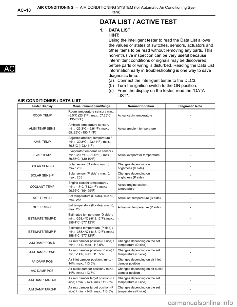
DATA LIST / ACTIVE TEST
1. DATA LIST
HINT:
Using the intelligent tester to read the Data List allows
the values or states of switches, sensors, actuators and
other items to be read without removing any parts. This
non-intrusive inspection can be very useful because
intermittent conditions or signals may be discovered
before parts or wiring is disturbed. Reading the Data List
information early in troubleshooting is one way to save
diagnostic time.
(a) Connect the intelligent tester to the DLC3.
(b) Turn the ignition switch to the ON position.
(c) From the display on the tester, read the "DATA
LIST".
AIR CONDITIONER / DATA LIST
Tester Display Measurement Item/Range Normal Condition Diagnostic Note
ROOM TEMPRoom temperature sensor / min.:
-6.5
C (20.3F), max.: 57.25C
(135.05
F)Actual cabin temperature -
AMBI TEMP SENSAmbient temperature sensor /
min.: -23.3
C (-9.94F), max.:
65..95C (150.71F)Actual ambient temperature -
AMBI TEMPAdjusted ambient temperature /
min.: -30.8
C (-23.44F), max.:
50.8
C (123.44F)--
EVAP TEMPEvaporator temperature sensor /
min.: -29.7
C (-21.46F), max.:
59.55
C (139.19F)Actual evaporator temperature -
SOLAR SENS-DSolar sensor (D side) / min.: 0,
max.: 255Changes depending on
brightness (D side)-
SOLAR SENS-PSolar sensor (P side) / min.: 0,
max.: 255Changes depending on
brightness (P side)-
COOLANT TEMPEngine coolant temperature /
min.: 1.3
C (34.34F), max.:
90.55C (194.99F)Actual engine coolant
temperature-
SET TEMP-DSet temperature (D side) / min.: 0,
max. 255Actual set temperature (D side) -
SET TEMP-PSet temperature (P side) / min.: 0,
max. 255Actual set temperature (P side) -
ESTIMATE TEMP-DEstimated temperature (D side) /
min.: -358.4
C (-613.12F), max.:
358.4
C (677.12F)--
ESTIMATE TEMP-PEstimated temperature (P side) /
min.: -358.4
C (-613.12F), max.:
358.4
C (677.12F)--
A/M DAMP POS-DAir mix damper position (D side) /
min.: -14%, max.: 113.5%Changes depending on the set
temperature (D side)-
A/M DAMP POS-PAir mix damper position (P side) /
min.: -14%, max.: 113.5%Changes depending on the set
temperature (P side)-
A/I DAMP POSAir inlet damper position / min.: -
14%, max.: 113.5%Changes depending on air inlet
damper position-
A/O DAMP POSAir outlet damper position / min.: -
14%, max.: 113.5%Changes depending on air outlet
damper position-
A/M DAMP TARG-DAir mix damper target position (D
side) / min.: -14%, max.: 113.5%Changes depending on the set
temperature (D side)-
A/M DAMP TARG-PAir mix damper target position (P
side) / min.: -14%, max.: 113.5%Changes depending on the set
temperature (P side)-
Page 2919 of 3000

AIR CONDITIONING – AIR CONDITIONING SYSTEM (for Automatic Air Conditioning Sys-
tem)AC–19
AC
HINT:
*1: It differs depending on the user setting.
2. ACTIVE TEST
HINT:
Using the intelligent tester to perform Active Tests allows
relays, VSVs, actuators and other items to be operated
without removing any parts. This non-intrusive functional
inspection can be very useful because intermittent
operation may be discovered before parts or wiring is
disturbed. Performing Active Tests early in
troubleshooting is one way to save diagnostic time. Data
List information can be displayed while performing Active
Tests.
(a) Connect the intelligent tester to the DLC3.
A/I DAMP TARGAir inlet damper target position /
min.: -14%, max.: 113.5%Changes depending on air inlet
damper position-
A/O DAMP TARGAir outlet damper target position /
min.: -14%, max.: 113.5%Changes depending on air outlet
damper position-
BLOWER LEVELBlower motor speed level / min.:
Level 0, max.: Level 31Changes depending on blower
level-
REAR ROOM TEMPRoom temperature sensor (Rear)
/ min.: -6.5
C (20.3F), max.:
57.25C (135.05F)Actual cabin temperature (Rear) -
R-EVAP TEMP SENRr. EVAP temperature sensor
(Rear) / min.: -29.7
C (-21.46F),
max.: 59.55
C (139.19F)Actual evaporator temperature
(Rear)-
SET TEMP REARSet temperature (Rear) / min.: 0,
max. 255Actual set temperature -
ESTIMATE TEMP-REstimated temperature (Rear) /
min.: -358.4
C (-613.12F), max.:
358.4
C (677.12F)--
A/M DAMP POS-RAir mix damper position (Rear) /
min.: -14%, max.: 113.5%Changes depending on the set
temperature (Rear)-
A/O DAMP POS-RAir outlet mode damper position
(Rear) / min.: -14%, max.: 113.5%Changes depending on air outlet
damper position (Rear)-
A/M DAMP TARG-RAir mix damper target position
(Rear) / min.: -14%, max.: 113.5%Changes depending on the set
temperature (Rear)-
A/O DAMP TARG-RAir outlet damper target position
(Rear) / min.: -14%, max.: 113.5%Changes depending on air outlet
damper position (Rear)-
BLOWER LEVEL-RBlower motor speed level (Rear) /
min.: Level 0, max: Level 31Changes depending on blower
level (Rear)-
SET TEMP SHIFT Shift set temperatureChanges depending on shift set
temperature *1-
AIR INLET MODE Air inlet modeChanges depending on air inlet
mode *1-
COMPRESSOR MODE Compressor modeChanges depending on
compressor mode *1-
COMPRS/DEF MODE Compressor/DEF operation modeChanges depending on
compressor/DEF operation mode
*1-
FOOT/DEF OPER Foot/DEF auto modeChanges depending on Foot/DEF
auto mode *1-
AUTO BLOW UPFoot/DEF automatic blow up
functionChanges depending on Foot/DEF
automatic blow up function *1-
#CODESNumber of Trouble Codes / min.:
0, max.: 255-- Tester Display Measurement Item/Range Normal Condition Diagnostic Note
Page 2920 of 3000

AC–20AIR CONDITIONING – AIR CONDITIONING SYSTEM (for Automatic Air Conditioning Sys-
tem)
AC
(b) Turn the ignition switch to the ON position.
(c) From the display on the tester, read the "ACTIVE
TEST".
Tester Display Test Part Control Range Diagnostic Note
BLOWER MOTOR Blower motor min.: Level 0, max.: Level 31 -
AIR MIX DAMP-D Air mix damper (D side) min.: -14%, max: 113.5% -
AIR MIX DAMP-P Air mix damper (P side) min.: -14%, max: 113.5% -
A/O MODE DAMP-DAir outlet damper position (D
side)min.: -14%, max: 113.5% -
A/I DAMP-LINEAR Air inlet damper position (linear) min.: -14%, max: 113.5% -
REAR BLOWER Blower motor (Rear) OFF, LO, HI -
A/O MODE DAMP-R Air outlet damper position (Rear) min.: -14%, max: 113.5% -
AIR MIX DAMP-R Air mix damper (Rear) min.: -14%, max: 113.5% -
A/C MAG CLUTCH Magnetic clutch relay OFF, ON -
Page 2922 of 3000

AC–22AIR CONDITIONING – AIR CONDITIONING SYSTEM (for Automatic Air Conditioning Sys-
tem)
AC
B1422/22 Compressor Lock Sensor
Circuit1. A/C compressor (A/C
lock sensor)
2. Compressor drive belt
3. Harness or connector
between compressor and
magnetic clutch (A/C lock
sensor)
4. A/C amplifier
5. CAN communication
system
6. Multiplex
communication system
(BEAN)-AC-47
B1423/23 Pressure Sensor Circuit 1. Pressure sensor
2. Harness or connector
between pressure sensor
and A/C amplifier
3. A/C amplifier
4. Expansion valve
(blocked, stuck)
5. Condenser (blocked,
deterioration of cooling
capacity due to dirt)
6. Cooler dryer (moisture
in the refrigerant cycle
cannot be absorbed)
7. Cooling fan system
(condenser cannot be
cooled down)
8. A/C system (leaks,
blocked)-AC-51
B1424/24
*2Solar Sensor Circuit
(Driver Side)1. Solar sensor
2. Harness or connector
between solar sensor and
A/C amplifier (A/C control
assembly)
3. Harness or connector
between solar sensor and
body ECU
4. A/C amplifier (A/C
control assembly)
5. Body ECUMemorized*3
(8.5 min. or more)
-AC-64
B1431/31 Air Mix Damper Position
Sensor Circuit (Passenger
Side)1. Air mix damper position
sensor
2. A/C amplifier (A/C
control assembly)
3. Harness or connector
between air mix damper
position sensor and A/C
amplifier (A/C control
assembly)Memorized
(1 min. or more)AC-69
B1432/32 Air Inlet Damper Position
Sensor Circuit1. Air inlet damper position
sensor (Air inlet control
servo motor)
2. A/C amplifier (A/C
control assembly)
3. Harness or connector
between air inlet damper
position sensor and A/C
amplifier (A/C control
assembly)Memorized
(1 min. or more)AC-73 DTC Code Detection Item Trouble Area Memory See page
Page 2923 of 3000

AIR CONDITIONING – AIR CONDITIONING SYSTEM (for Automatic Air Conditioning Sys-
tem)AC–23
AC
B1433/33 Air Outlet Damper Position
Sensor Circuit1. Air outlet damper
position sensor (Air outlet
control servo motor)
2. A/C amplifier (A/C
control assembly)
3. Harness or connector
between air outlet damper
position sensor and A/C
amplifier (A/C control
assembly)Memorized
(1 min. or more)AC-77
B1436/36 Air Mix Damper Position
Sensor Circuit (Driver
Side)1. Air mix damper position
sensor (Air mix control
servo motor)
2. Harness or connector
between air mix damper
position sensor and A/C
amplifier (A/C control
assembly)
3. A/C amplifier (A/C
control assembly)Memorized
(1 min. or more)AC-81
B1437/37 Rear Air Mix Damper
Position Sensor Circuit1. Rear air mix damper
position sensor (Rear air
mix control servo motor)
2. A/C amplifier (A/C
control assembly)
3. Harness or connector
between rear air mix
damper position sensor
and A/C amplifier (A/C
control assembly)AC-85
B1439/39 Rear Air Outlet Damper
Position Sensor Circuit1. Rear air outlet damper
position sensor (Rear air
outlet control servo motor)
2. Harness or connector
between rear air outlet
damper position sensor
and A/C amplifier (A/C
control assembly)
3. A/C amplifier (A/C
control assembly)AC-89
B1441/41 Air Mix Damper Control
Servo Motor Circuit
(Passenger Side)1. Air mix control servo
motor
2. Harness or connector
between air mix control
servo motor and A/C
amplifier (A/C control
assembly)
3. A/C amplifier (A/C
control assembly)Memorized
(15 sec.)AC-93
B1442/42 Air Inlet Damper Control
Servo Motor Circuit1. Air inlet control servo
motor
2. Harness or connector
between air inlet control
servo motor and A/C
amplifier (A/C control
assembly)
3. A/C amplifier (A/C
control assembly)Memorized
(15 sec.)AC-98
B1443/43 Air Outlet Damper Control
Servo Motor Circuit1. Air outlet control servo
motor
2. Harness or connector
between air outlet control
servo motor and A/C
amplifier (A/C control
assembly)
3. A/C amplifier (A/C
control assembly)Memorized
(15 sec.)AC-103 DTC Code Detection Item Trouble Area Memory See page