abs trouble code TOYOTA SIENNA 2007 Service Repair Manual
[x] Cancel search | Manufacturer: TOYOTA, Model Year: 2007, Model line: SIENNA, Model: TOYOTA SIENNA 2007Pages: 3000, PDF Size: 52.26 MB
Page 181 of 3000
BRAKE CONTROL – ANTI-LOCK BRAKE SYSTEMBC–5
BC
• After the ABS warning light goes off and if
vehicle speed exceeds 50 mph (80 km/h), the
signal check code will be stored again.
Decelerate or stop the vehicle before the
speed reaches 50 mph (80 km/h).
• If the signal check has not been completed,
the ABS warning light blinks while driving
and the ABS system does not operate.
HINT:
When the signal check has been completed, the
ABS warning light goes off while driving and blinks
in the Test Mode pattern while stationary.
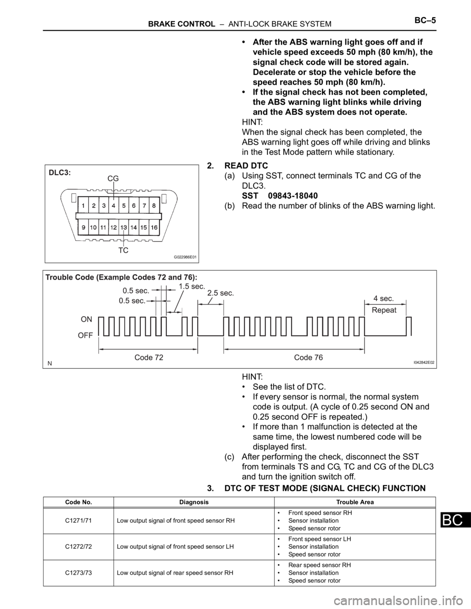
2. READ DTC
(a) Using SST, connect terminals TC and CG of the
DLC3.
SST 09843-18040
(b) Read the number of blinks of the ABS warning light.
HINT:
• See the list of DTC.
• If every sensor is normal, the normal system
code is output. (A cycle of 0.25 second ON and
0.25 second OFF is repeated.)
• If more than 1 malfunction is detected at the
same time, the lowest numbered code will be
displayed first.
(c) After performing the check, disconnect the SST
from terminals TS and CG, TC and CG of the DLC3
and turn the ignition switch off.
3. DTC OF TEST MODE (SIGNAL CHECK) FUNCTION
G022986E01
I042842E02
Code No. Diagnosis Trouble Area
C1271/71 Low output signal of front speed sensor RH• Front speed sensor RH
• Sensor installation
• Speed sensor rotor
C1272/72 Low output signal of front speed sensor LH• Front speed sensor LH
• Sensor installation
• Speed sensor rotor
C1273/73 Low output signal of rear speed sensor RH• Rear speed sensor RH
• Sensor installation
• Speed sensor rotor
Page 183 of 3000
BRAKE CONTROL – ANTI-LOCK BRAKE SYSTEMBC–7
BC
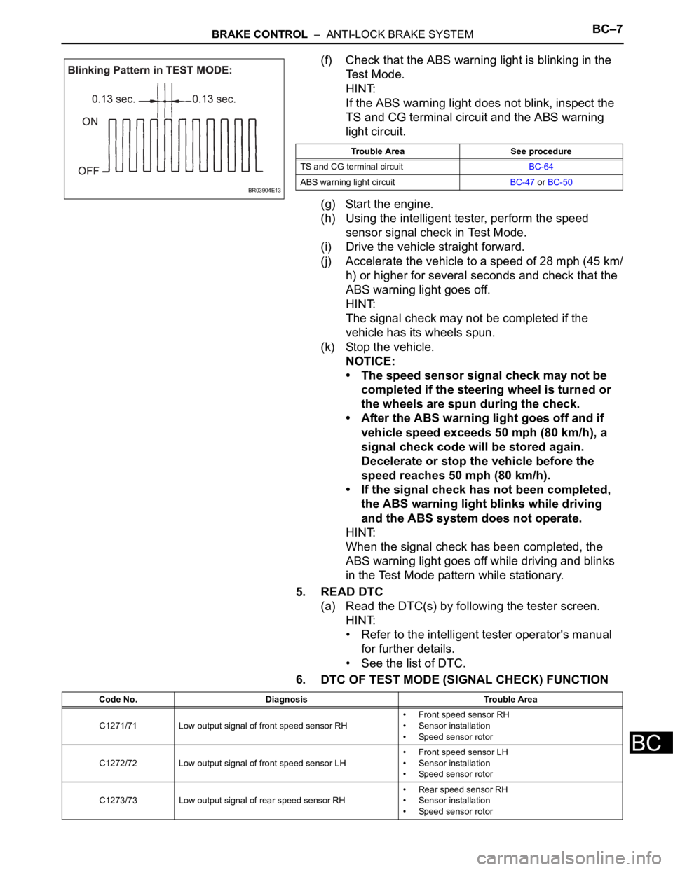
(f) Check that the ABS warning light is blinking in the
Test Mode.
HINT:
If the ABS warning light does not blink, inspect the
TS and CG terminal circuit and the ABS warning
light circuit.
(g) Start the engine.
(h) Using the intelligent tester, perform the speed
sensor signal check in Test Mode.
(i) Drive the vehicle straight forward.
(j) Accelerate the vehicle to a speed of 28 mph (45 km/
h) or higher for several seconds and check that the
ABS warning light goes off.
HINT:
The signal check may not be completed if the
vehicle has its wheels spun.
(k) Stop the vehicle.
NOTICE:
• The speed sensor signal check may not be
completed if the steering wheel is turned or
the wheels are spun during the check.
• After the ABS warning light goes off and if
vehicle speed exceeds 50 mph (80 km/h), a
signal check code will be stored again.
Decelerate or stop the vehicle before the
speed reaches 50 mph (80 km/h).
• If the signal check has not been completed,
the ABS warning light blinks while driving
and the ABS system does not operate.
HINT:
When the signal check has been completed, the
ABS warning light goes off while driving and blinks
in the Test Mode pattern while stationary.
5. READ DTC
(a) Read the DTC(s) by following the tester screen.
HINT:
• Refer to the intelligent tester operator's manual
for further details.
• See the list of DTC.
6. DTC OF TEST MODE (SIGNAL CHECK) FUNCTION
BR03904E13
Trouble Area See procedure
TS and CG terminal circuitBC-64
ABS warning light circuitBC-47 or BC-50
Code No. Diagnosis Trouble Area
C1271/71 Low output signal of front speed sensor RH• Front speed sensor RH
• Sensor installation
• Speed sensor rotor
C1272/72 Low output signal of front speed sensor LH• Front speed sensor LH
• Sensor installation
• Speed sensor rotor
C1273/73 Low output signal of rear speed sensor RH• Rear speed sensor RH
• Sensor installation
• Speed sensor rotor
Page 2282 of 3000

TW–38TIRE AND WHEEL – TIRE PRESSURE WARNING SYSTEM
TW
DATA LIST / ACTIVE TEST
1. DATA LIST
HINT:
Using the intelligent tester to read the DATA LIST allows
the values or states of switches, sensor, actuators and
other items to be read without removing any parts. This
non-intrusive inspection can be very useful because
intermittent conditions or signals may be discovered
before parts or wiring is disturbed. Reading the DATA
LIST information early in troubleshooting is one way to
save diagnostic time.
NOTICE:
In the table below, the values listed under "Normal
Condition" are reference values. Do not depend
solely on these reference values when deciding
whether a part is faulty or not.
(a) Make sure that the ignition switch is off.
(b) Connect the intelligent tester to DLC3.
(c) Turn the ignition switch to the ON position.
(d) Following the display on the intelligent tester, read
"DATA LIST".
Tester Display Measurement Item/Range Normal Condition Diagnostic Note
MODE STATUSTire pressure warning system mode/NORMAL
or REG 2nd or REG M or TESTNORMAL: Normal mode
TEST: Test mode-
MAIN TIRENumber of main tire ID to be registered/0, 1, 2,
3, 40 to 4 should be displayed -
VEHICLE SPDVehicle speed reading/min.: 0 km/h (0 mph),
max.: 255 km/h (158 mph)Actual vehicle speedSpeed indicated on the
combination meter
REGIT ID1 CODE
Registered ID1 code/min.: 0, max.: FFFFFFF
*1The ID No. registered in the
transmitter ID1 is displayed-
REGIT ID2 CODE
Registered ID2 code/min.: 0, max.: FFFFFFF
*1The ID No. registered in the
transmitter ID2 is displayed-
REGIT ID3 CODE
Registered ID3 code/min.: 0, max.: FFFFFFF
*1The ID No. registered in the
transmitter ID3 is displayed-
REGIT ID4 CODE
Registered ID4 code/min.: 0, max.: FFFFFFF
*1The ID No. registered in the
transmitter ID4 is displayed-
TRANS STATUS ID code transmission status/FINISH or NOW FINISH or NOW -
INITIAL SW Tire pressure warning reset switch/ON, OFFON: Switch on
OFF: Switch off-
TIREPRESS1ID1 tire inflation pressure (Absolute pressure) /
min.: 100 kPa (1 kgf/cm
2, 14 psi)
max.: 449.35 kPa (4.5 kgf/cm2, 63 psi)Actual tire inflation pressureIf 100 kPa (1 kgf/cm
2, 14 psi)
for absolute pressure is
displayed, the data has not
been received.
*2
TIREPRESS2ID2 tire inflation pressure (Absolute pressure) /
min.: 100 kPa (1 kgf/cm2, 14 psi)
max.: 449.35 kPa (4.5 kgf/cm2, 63 psi)Actual tire inflation pressureIf 100 kPa (1 kgf/cm
2, 14 psi)
for absolute pressure is
displayed, the data has not
been received.
*2
TIREPRESS3ID3 tire inflation pressure (Absolute pressure) /
min.: 100 kPa (1 kgf/cm2, 14 psi)
max.: 449.35 kPa (4.5 kgf/cm2, 63 psi)Actual tire inflation pressureIf 100 kPa (1 kgf/cm
2, 14 psi)
for absolute pressure is
displayed, the data has not
been received.
*2
TIREPRESS4ID4 tire inflation pressure (Absolute pressure) /
min.: 100 kPa (1 kgf/cm2, 14 psi)
max.: 449.35 kPa (4.5 kgf/cm2, 63 psi)Actual tire inflation pressureIf 100 kPa (1 kgf/cm
2, 14 psi)
for absolute pressure is
displayed, the data has not
been received.
*2
Page 2356 of 3000

TW–38TIRE AND WHEEL – TIRE PRESSURE WARNING SYSTEM
TW
DATA LIST / ACTIVE TEST
1. DATA LIST
HINT:
Using the intelligent tester to read the DATA LIST allows
the values or states of switches, sensor, actuators and
other items to be read without removing any parts. This
non-intrusive inspection can be very useful because
intermittent conditions or signals may be discovered
before parts or wiring is disturbed. Reading the DATA
LIST information early in troubleshooting is one way to
save diagnostic time.
NOTICE:
In the table below, the values listed under "Normal
Condition" are reference values. Do not depend
solely on these reference values when deciding
whether a part is faulty or not.
(a) Make sure that the ignition switch is off.
(b) Connect the intelligent tester to DLC3.
(c) Turn the ignition switch to the ON position.
(d) Following the display on the intelligent tester, read
"DATA LIST".
Tester Display Measurement Item/Range Normal Condition Diagnostic Note
MODE STATUSTire pressure warning system mode/NORMAL
or REG 2nd or REG M or TESTNORMAL: Normal mode
TEST: Test mode-
MAIN TIRENumber of main tire ID to be registered/0, 1, 2,
3, 40 to 4 should be displayed -
VEHICLE SPDVehicle speed reading/min.: 0 km/h (0 mph),
max.: 255 km/h (158 mph)Actual vehicle speedSpeed indicated on the
combination meter
REGIT ID1 CODE
Registered ID1 code/min.: 0, max.: FFFFFFF
*1The ID No. registered in the
transmitter ID1 is displayed-
REGIT ID2 CODE
Registered ID2 code/min.: 0, max.: FFFFFFF
*1The ID No. registered in the
transmitter ID2 is displayed-
REGIT ID3 CODE
Registered ID3 code/min.: 0, max.: FFFFFFF
*1The ID No. registered in the
transmitter ID3 is displayed-
REGIT ID4 CODE
Registered ID4 code/min.: 0, max.: FFFFFFF
*1The ID No. registered in the
transmitter ID4 is displayed-
TRANS STATUS ID code transmission status/FINISH or NOW FINISH or NOW -
INITIAL SW Tire pressure warning reset switch/ON, OFFON: Switch on
OFF: Switch off-
TIREPRESS1ID1 tire inflation pressure (Absolute pressure) /
min.: 100 kPa (1 kgf/cm
2, 14 psi)
max.: 449.35 kPa (4.5 kgf/cm2, 63 psi)Actual tire inflation pressureIf 100 kPa (1 kgf/cm
2, 14 psi)
for absolute pressure is
displayed, the data has not
been received.
*2
TIREPRESS2ID2 tire inflation pressure (Absolute pressure) /
min.: 100 kPa (1 kgf/cm2, 14 psi)
max.: 449.35 kPa (4.5 kgf/cm2, 63 psi)Actual tire inflation pressureIf 100 kPa (1 kgf/cm
2, 14 psi)
for absolute pressure is
displayed, the data has not
been received.
*2
TIREPRESS3ID3 tire inflation pressure (Absolute pressure) /
min.: 100 kPa (1 kgf/cm2, 14 psi)
max.: 449.35 kPa (4.5 kgf/cm2, 63 psi)Actual tire inflation pressureIf 100 kPa (1 kgf/cm
2, 14 psi)
for absolute pressure is
displayed, the data has not
been received.
*2
TIREPRESS4ID4 tire inflation pressure (Absolute pressure) /
min.: 100 kPa (1 kgf/cm2, 14 psi)
max.: 449.35 kPa (4.5 kgf/cm2, 63 psi)Actual tire inflation pressureIf 100 kPa (1 kgf/cm
2, 14 psi)
for absolute pressure is
displayed, the data has not
been received.
*2
Page 2360 of 3000

BRAKE CONTROL – ANTI-LOCK BRAKE SYSTEMBC–9
BC
PROBLEM SYMPTOMS TABLE
If there are no DTCs output but the problem still occurs,
check the circuits for each problem symptom in the order
given in the table below and proceed to the relevant
troubleshooting page.
NOTICE:
When replacing the brake actuator assembly, sensor,
etc., turn the ignition switch off.
HINT:
Inspect the fuse and relay before investigating the suspected
areas as shown in the table below. Inspect each malfunction
circuit in numerical order for the corresponding symptom.
Anti-lock brake system:
Symptom Suspected Area See page
ABS does not operate1. Check the DTC again and make sure that the normal
system code is output.BC-10
2. IG power source circuitBC-37
3. Front speed sensor circuitBC-17
4. Rear speed sensor circuitBC-23
5. Check the brake actuator with the intelligent tester. If
abnormal, check the hydraulic circuit for leakage.BC-183
6. If the symptoms still occur even after the above circuits in
suspected areas have been inspected and proved to be
normal, replace the brake actuator assembly.BC-184
ABS does not operate efficiently1. Check the DTC again and make sure that the normal
system code is output.BC-10
2. Front speed sensor circuitBC-17
3. Rear speed sensor circuitBC-23
4. Stop light switch circuitBC-41
5. Check the brake actuator with intelligent tester. If abnormal,
check that hydraulic circuit for leakage.BC-183
6. If the symptoms still occur even after the above circuits in
suspected areas have been inspected and proved to be
normal, replace the brake actuator assembly.BC-184
ABS warning light abnormal (Remains on)1. ABS warning light circuitBC-47
2. Brake actuator assemblyBC-184
ABS warning light abnormal (Does not come on)1. ABS warning light circuitBC-50
2. Brake actuator assemblyBC-184
BRAKE warning light abnormal (Remains on)1. BRAKE warning light circuitBC-52
2. Brake actuator assemblyBC-184
BRAKE warning light abnormal (Does not come on)1. BRAKE warning light circuitBC-59
2. Brake actuator assemblyBC-184
DTC check cannot be done1. Check the DTC again and make sure that the normal
system code is output.BC-10
2. TC and CG terminal circuitBC-61
3. If the symptoms still occur even after the above circuits in
suspected areas have been inspected and proved to be
normal, replace the brake actuator assembly.BC-184
Test mode (Signal check) cannot be done1. TS and CG terminal circuitBC-64
2. Brake actuator assemblyBC-184
Page 2362 of 3000
BRAKE CONTROL – ANTI-LOCK BRAKE SYSTEMBC–11
BC
DIAGNOSIS SYSTEM
1. DESCRIPTION
(a) Release the parking brake pedal.
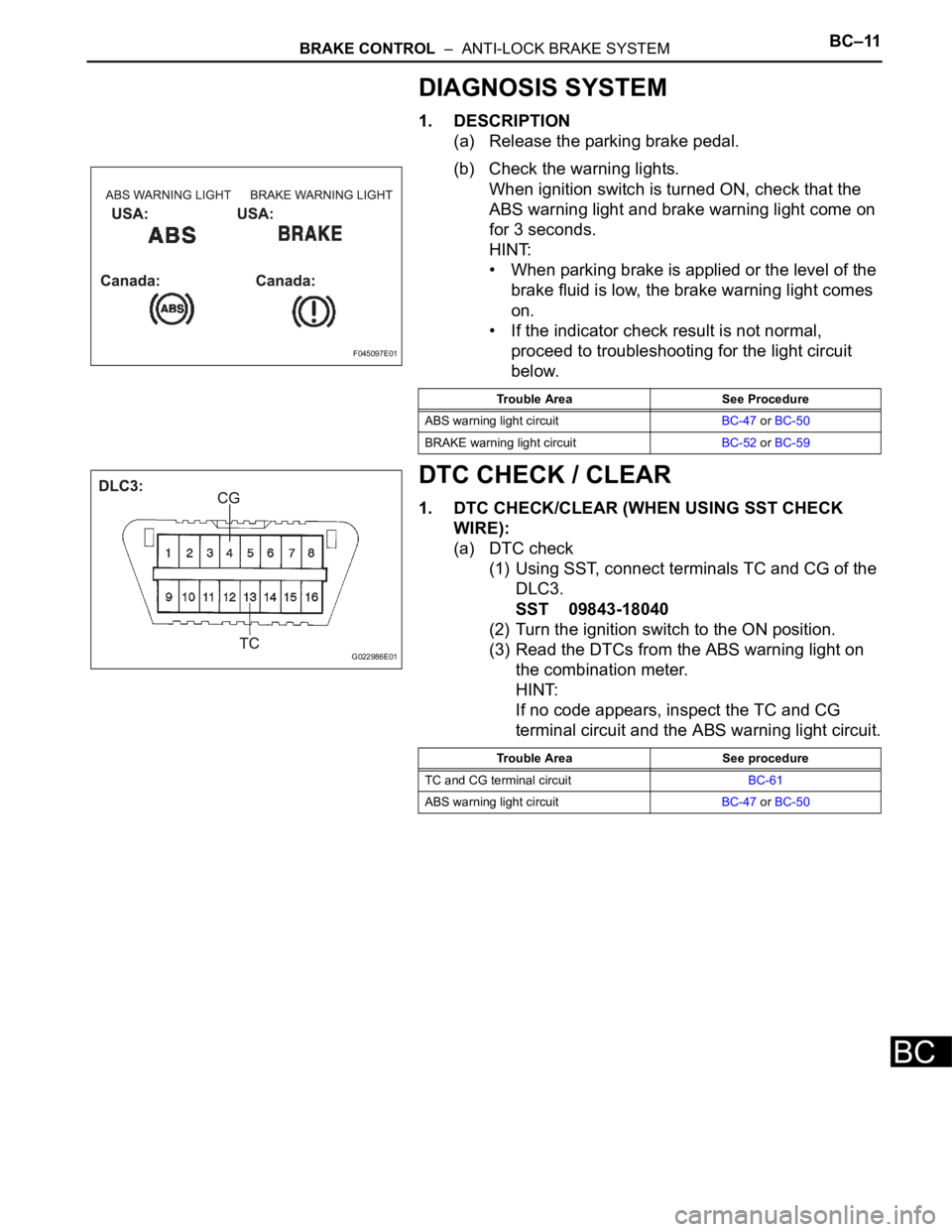
(b) Check the warning lights.
When ignition switch is turned ON, check that the
ABS warning light and brake warning light come on
for 3 seconds.
HINT:
• When parking brake is applied or the level of the
brake fluid is low, the brake warning light comes
on.
• If the indicator check result is not normal,
proceed to troubleshooting for the light circuit
below.
DTC CHECK / CLEAR
1. DTC CHECK/CLEAR (WHEN USING SST CHECK
WIRE):
(a) DTC check
(1) Using SST, connect terminals TC and CG of the
DLC3.
SST 09843-18040
(2) Turn the ignition switch to the ON position.
(3) Read the DTCs from the ABS warning light on
the combination meter.
HINT:
If no code appears, inspect the TC and CG
terminal circuit and the ABS warning light circuit.
F045097E01
Trouble Area See Procedure
ABS warning light circuitBC-47 or BC-50
BRAKE warning light circuitBC-52 or BC-59
G022986E01
Trouble Area See procedure
TC and CG terminal circuitBC-61
ABS warning light circuitBC-47 or BC-50
Page 2369 of 3000
BRAKE CONTROL – ANTI-LOCK BRAKE SYSTEMBC–5
BC
• After the ABS warning light goes off and if
vehicle speed exceeds 50 mph (80 km/h), the
signal check code will be stored again.
Decelerate or stop the vehicle before the
speed reaches 50 mph (80 km/h).
• If the signal check has not been completed,
the ABS warning light blinks while driving
and the ABS system does not operate.
HINT:
When the signal check has been completed, the
ABS warning light goes off while driving and blinks
in the Test Mode pattern while stationary.
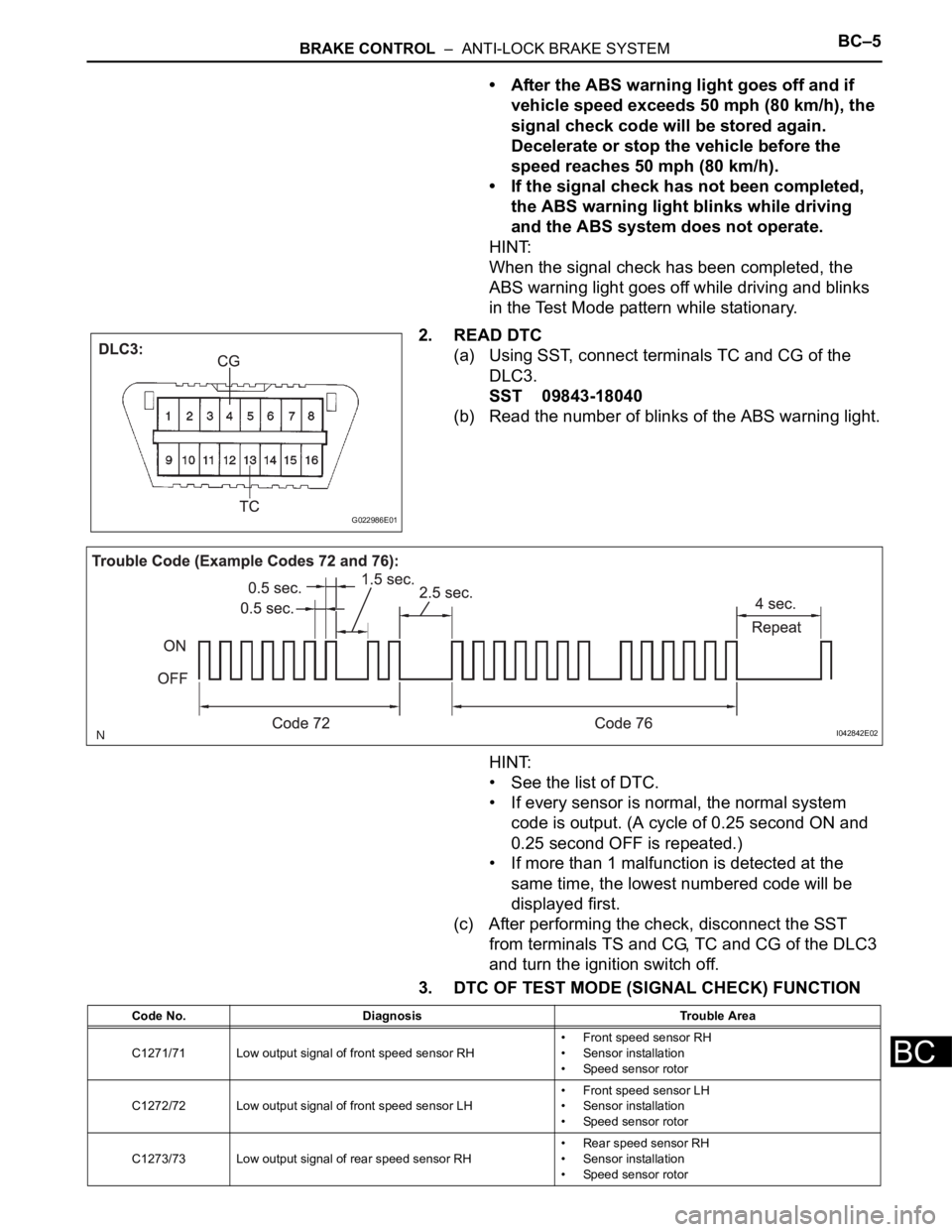
2. READ DTC
(a) Using SST, connect terminals TC and CG of the
DLC3.
SST 09843-18040
(b) Read the number of blinks of the ABS warning light.
HINT:
• See the list of DTC.
• If every sensor is normal, the normal system
code is output. (A cycle of 0.25 second ON and
0.25 second OFF is repeated.)
• If more than 1 malfunction is detected at the
same time, the lowest numbered code will be
displayed first.
(c) After performing the check, disconnect the SST
from terminals TS and CG, TC and CG of the DLC3
and turn the ignition switch off.
3. DTC OF TEST MODE (SIGNAL CHECK) FUNCTION
G022986E01
I042842E02
Code No. Diagnosis Trouble Area
C1271/71 Low output signal of front speed sensor RH• Front speed sensor RH
• Sensor installation
• Speed sensor rotor
C1272/72 Low output signal of front speed sensor LH• Front speed sensor LH
• Sensor installation
• Speed sensor rotor
C1273/73 Low output signal of rear speed sensor RH• Rear speed sensor RH
• Sensor installation
• Speed sensor rotor
Page 2371 of 3000
BRAKE CONTROL – ANTI-LOCK BRAKE SYSTEMBC–7
BC
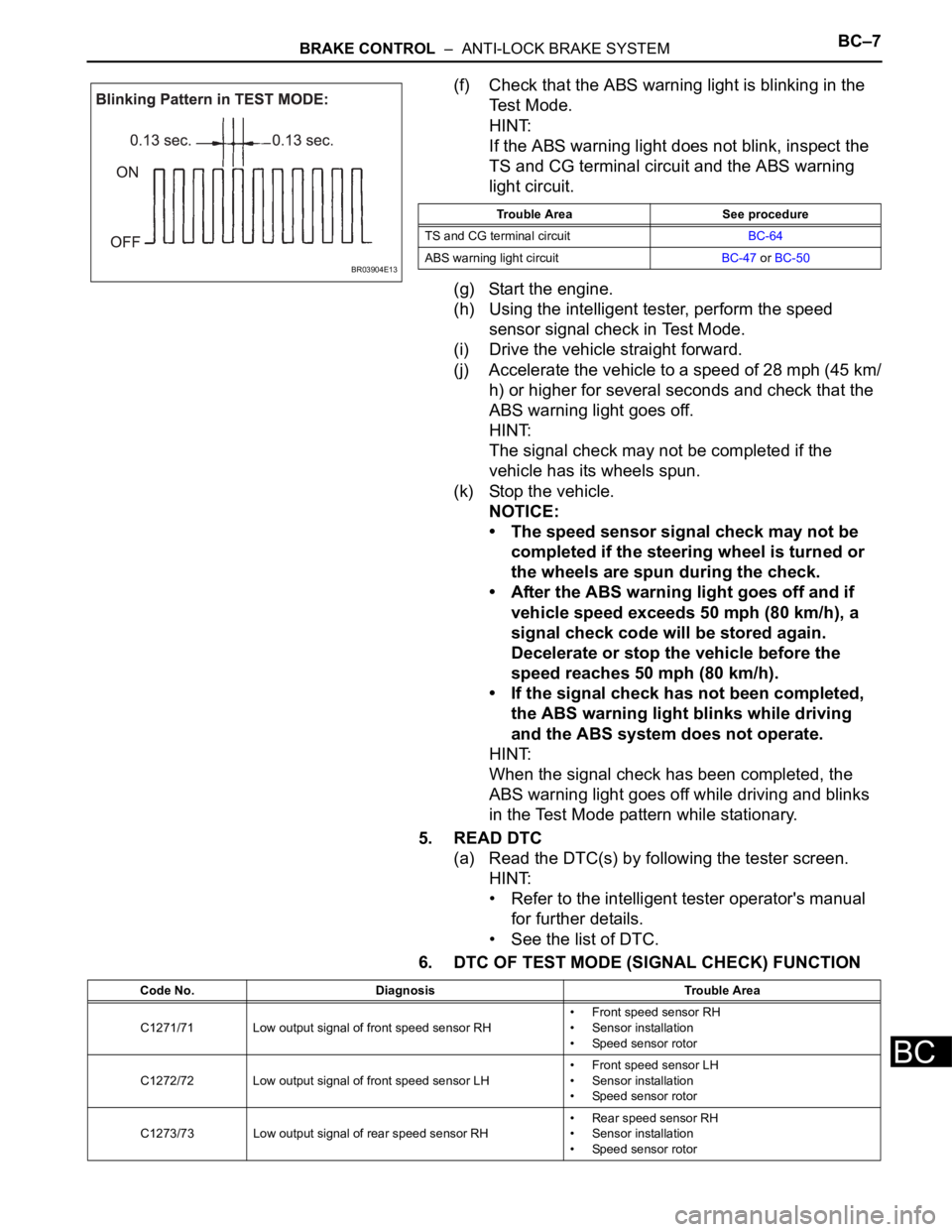
(f) Check that the ABS warning light is blinking in the
Test Mode.
HINT:
If the ABS warning light does not blink, inspect the
TS and CG terminal circuit and the ABS warning
light circuit.
(g) Start the engine.
(h) Using the intelligent tester, perform the speed
sensor signal check in Test Mode.
(i) Drive the vehicle straight forward.
(j) Accelerate the vehicle to a speed of 28 mph (45 km/
h) or higher for several seconds and check that the
ABS warning light goes off.
HINT:
The signal check may not be completed if the
vehicle has its wheels spun.
(k) Stop the vehicle.
NOTICE:
• The speed sensor signal check may not be
completed if the steering wheel is turned or
the wheels are spun during the check.
• After the ABS warning light goes off and if
vehicle speed exceeds 50 mph (80 km/h), a
signal check code will be stored again.
Decelerate or stop the vehicle before the
speed reaches 50 mph (80 km/h).
• If the signal check has not been completed,
the ABS warning light blinks while driving
and the ABS system does not operate.
HINT:
When the signal check has been completed, the
ABS warning light goes off while driving and blinks
in the Test Mode pattern while stationary.
5. READ DTC
(a) Read the DTC(s) by following the tester screen.
HINT:
• Refer to the intelligent tester operator's manual
for further details.
• See the list of DTC.
6. DTC OF TEST MODE (SIGNAL CHECK) FUNCTION
BR03904E13
Trouble Area See procedure
TS and CG terminal circuitBC-64
ABS warning light circuitBC-47 or BC-50
Code No. Diagnosis Trouble Area
C1271/71 Low output signal of front speed sensor RH• Front speed sensor RH
• Sensor installation
• Speed sensor rotor
C1272/72 Low output signal of front speed sensor LH• Front speed sensor LH
• Sensor installation
• Speed sensor rotor
C1273/73 Low output signal of rear speed sensor RH• Rear speed sensor RH
• Sensor installation
• Speed sensor rotor
Page 2379 of 3000

BRAKE CONTROL – ANTI-LOCK BRAKE SYSTEMBC–9
BC
PROBLEM SYMPTOMS TABLE
If there are no DTCs output but the problem still occurs,
check the circuits for each problem symptom in the order
given in the table below and proceed to the relevant
troubleshooting page.
NOTICE:
When replacing the brake actuator assembly, sensor,
etc., turn the ignition switch off.
HINT:
Inspect the fuse and relay before investigating the suspected
areas as shown in the table below. Inspect each malfunction
circuit in numerical order for the corresponding symptom.
Anti-lock brake system:
Symptom Suspected Area See page
ABS does not operate1. Check the DTC again and make sure that the normal
system code is output.BC-10
2. IG power source circuitBC-37
3. Front speed sensor circuitBC-17
4. Rear speed sensor circuitBC-23
5. Check the brake actuator with the intelligent tester. If
abnormal, check the hydraulic circuit for leakage.BC-183
6. If the symptoms still occur even after the above circuits in
suspected areas have been inspected and proved to be
normal, replace the brake actuator assembly.BC-184
ABS does not operate efficiently1. Check the DTC again and make sure that the normal
system code is output.BC-10
2. Front speed sensor circuitBC-17
3. Rear speed sensor circuitBC-23
4. Stop light switch circuitBC-41
5. Check the brake actuator with intelligent tester. If abnormal,
check that hydraulic circuit for leakage.BC-183
6. If the symptoms still occur even after the above circuits in
suspected areas have been inspected and proved to be
normal, replace the brake actuator assembly.BC-184
ABS warning light abnormal (Remains on)1. ABS warning light circuitBC-47
2. Brake actuator assemblyBC-184
ABS warning light abnormal (Does not come on)1. ABS warning light circuitBC-50
2. Brake actuator assemblyBC-184
BRAKE warning light abnormal (Remains on)1. BRAKE warning light circuitBC-52
2. Brake actuator assemblyBC-184
BRAKE warning light abnormal (Does not come on)1. BRAKE warning light circuitBC-59
2. Brake actuator assemblyBC-184
DTC check cannot be done1. Check the DTC again and make sure that the normal
system code is output.BC-10
2. TC and CG terminal circuitBC-61
3. If the symptoms still occur even after the above circuits in
suspected areas have been inspected and proved to be
normal, replace the brake actuator assembly.BC-184
Test mode (Signal check) cannot be done1. TS and CG terminal circuitBC-64
2. Brake actuator assemblyBC-184
Page 2381 of 3000
BRAKE CONTROL – ANTI-LOCK BRAKE SYSTEMBC–11
BC
DIAGNOSIS SYSTEM
1. DESCRIPTION
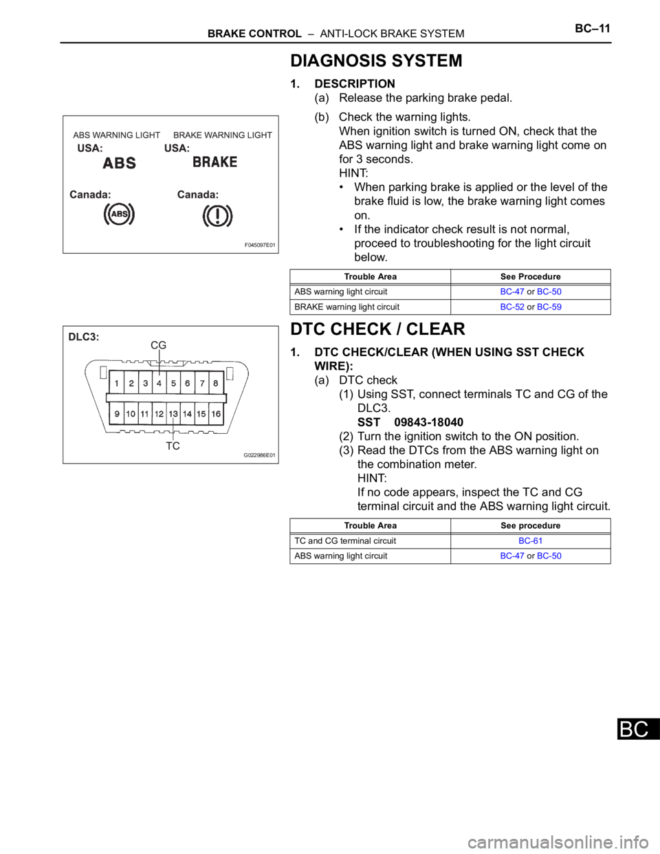
(a) Release the parking brake pedal.
(b) Check the warning lights.
When ignition switch is turned ON, check that the
ABS warning light and brake warning light come on
for 3 seconds.
HINT:
• When parking brake is applied or the level of the
brake fluid is low, the brake warning light comes
on.
• If the indicator check result is not normal,
proceed to troubleshooting for the light circuit
below.
DTC CHECK / CLEAR
1. DTC CHECK/CLEAR (WHEN USING SST CHECK
WIRE):
(a) DTC check
(1) Using SST, connect terminals TC and CG of the
DLC3.
SST 09843-18040
(2) Turn the ignition switch to the ON position.
(3) Read the DTCs from the ABS warning light on
the combination meter.
HINT:
If no code appears, inspect the TC and CG
terminal circuit and the ABS warning light circuit.
F045097E01
Trouble Area See Procedure
ABS warning light circuitBC-47 or BC-50
BRAKE warning light circuitBC-52 or BC-59
G022986E01
Trouble Area See procedure
TC and CG terminal circuitBC-61
ABS warning light circuitBC-47 or BC-50