heater TOYOTA SIENNA 2007 Service Repair Manual
[x] Cancel search | Manufacturer: TOYOTA, Model Year: 2007, Model line: SIENNA, Model: TOYOTA SIENNA 2007Pages: 3000, PDF Size: 52.26 MB
Page 7 of 3000

PP–6PREPARATION – 2GR-FE ENGINE MECHANICAL
PP
EQUIPMENT
Abrasive compound
Brush
Caliper gauge
Carbide cutter (30
)
Carbide cutter (45
)
Carbide cutter (60
)
Carbide cutter (75
)
Connecting rod aligner
Cylinder gauge
Dial indicator
Dye penetrant
Engine tune-up tester
Groove cleaning tool
Heater
Micrometer
Piston ring compressor
Piston ring expander
Plastigage
Precision straight edge
Press
Reamer (5.5 mm)
Ridge reamer
Soft brush
Solvent
Spring tester
Steel square
Thermometer
To r q u e w r e n c h
Torx socket wrench
Valve seat cutter
Valve guide bushing brush
V-block
Vernier calipers
Wire brush
Bar
Chain Block
CO/HC meter
Compression gauge
Dial indicator with magnetic base
Engine Sling Device
Feeler gauge
Radiator cap tester
Slide calipers
Tachometer
Timing light
Wooden block
Deep socket wrench
Screwdriver
Hammer
Page 29 of 3000
EM–302GR-FE ENGINE MECHANICAL – ENGINE ASSEMBLY
EM
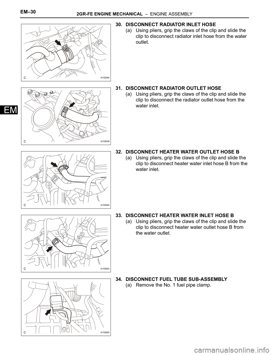
30. DISCONNECT RADIATOR INLET HOSE
(a) Using pliers, grip the claws of the clip and slide the
clip to disconnect radiator inlet hose from the water
outlet.
31. DISCONNECT RADIATOR OUTLET HOSE
(a) Using pliers, grip the claws of the clip and slide the
clip to disconnect the radiator outlet hose from the
water inlet.
32. DISCONNECT HEATER WATER OUTLET HOSE B
(a) Using pliers, grip the claws of the clip and slide the
clip to disconnect heater water inlet hose B from the
water inlet.
33. DISCONNECT HEATER WATER INLET HOSE B
(a) Using pliers, grip the claws of the clip and slide the
clip to disconnect heater water outlet hose B from
the water outlet.
34. DISCONNECT FUEL TUBE SUB-ASSEMBLY
(a) Remove the No. 1 fuel pipe clamp.
A155046
A155038
A155044
A155043
A155045
Page 55 of 3000
INTRODUCTION – HOW TO TROUBLESHOOT ECU CONTROLLED SYSTEMSIN–43
IN
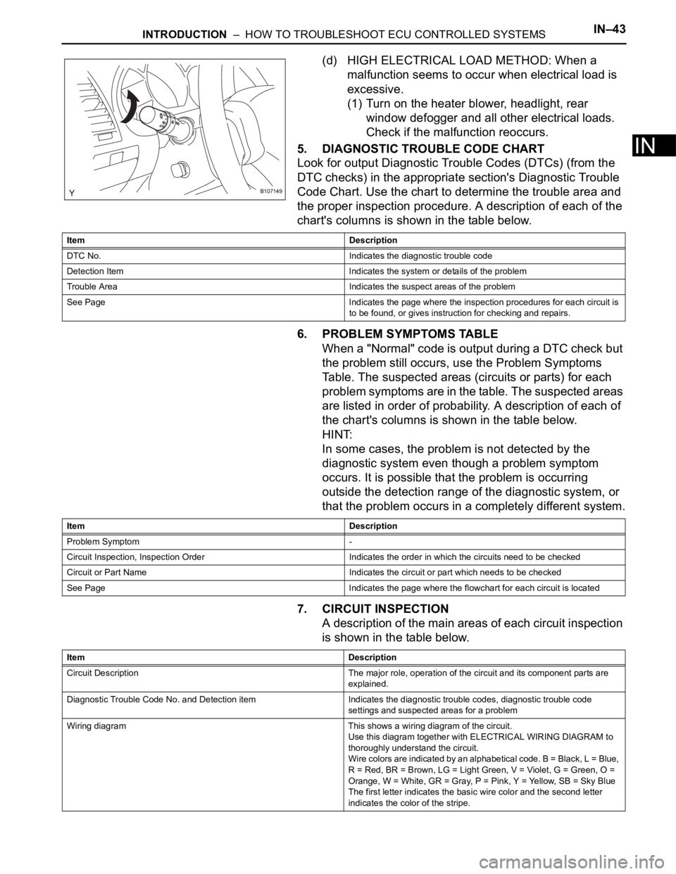
(d) HIGH ELECTRICAL LOAD METHOD: When a
malfunction seems to occur when electrical load is
excessive.
(1) Turn on the heater blower, headlight, rear
window defogger and all other electrical loads.
Check if the malfunction reoccurs.
5. DIAGNOSTIC TROUBLE CODE CHART
Look for output Diagnostic Trouble Codes (DTCs) (from the
DTC checks) in the appropriate section's Diagnostic Trouble
Code Chart. Use the chart to determine the trouble area and
the proper inspection procedure. A description of each of the
chart's columns is shown in the table below.
6. PROBLEM SYMPTOMS TABLE
When a "Normal" code is output during a DTC check but
the problem still occurs, use the Problem Symptoms
Table. The suspected areas (circuits or parts) for each
problem symptoms are in the table. The suspected areas
are listed in order of probability. A description of each of
the chart's columns is shown in the table below.
HINT:
In some cases, the problem is not detected by the
diagnostic system even though a problem symptom
occurs. It is possible that the problem is occurring
outside the detection range of the diagnostic system, or
that the problem occurs in a completely different system.
7. CIRCUIT INSPECTION
A description of the main areas of each circuit inspection
is shown in the table below.
B107149
Item Description
DTC No. Indicates the diagnostic trouble code
Detection Item Indicates the system or details of the problem
Trouble Area Indicates the suspect areas of the problem
See Page Indicates the page where the inspection procedures for each circuit is
to be found, or gives instruction for checking and repairs.
Item Description
Problem Symptom -
Circuit Inspection, Inspection Order Indicates the order in which the circuits need to be checked
Circuit or Part Name Indicates the circuit or part which needs to be checked
See Page Indicates the page where the flowchart for each circuit is located
Item Description
Circuit Description The major role, operation of the circuit and its component parts are
explained.
Diagnostic Trouble Code No. and Detection item Indicates the diagnostic trouble codes, diagnostic trouble code
settings and suspected areas for a problem
Wiring diagram This shows a wiring diagram of the circuit.
Use this diagram together with ELECTRICAL WIRING DIAGRAM to
thoroughly understand the circuit.
Wire colors are indicated by an alphabetical code. B = Black, L = Blue,
R = Red, BR = Brown, LG = Light Green, V = Violet, G = Green, O =
Orange, W = White, GR = Gray, P = Pink, Y = Yellow, SB = Sky Blue
The first letter indicates the basic wire color and the second letter
indicates the color of the stripe.
Page 57 of 3000

IN–50INTRODUCTION – TERMS
IN
GLOSSARY OF SAE AND TOYOTA
TERMS
This glossary lists all SAE-J1930 terms and abbreviations
used in this manual in compliance with SAE
recommendations, as well as their TOYOTA equivalents.
SAE
ABBREVIATIONSSAE TERMSTOYOTA TERMS
( )-ABBREVIATIONS
A/C Air Conditioning Air Conditioner
ACL Air Cleaner Air Cleaner, A/CL
AIR Secondary Air Injection Air Injection (AI)
AP Accelerator Pedal -
B+ Battery Positive Voltage +B, Battery Voltage
BARO Barometric Pressure HAC
CAC Charge Air Cooler Intercooler
CARB Carburetor Carburetor
CFI Continuous Fuel Injection -
CKP Crankshaft Position Crank Angle
CL Closed Loop Closed Loop
CMP Camshaft Position Cam Angle
CPP Clutch Pedal Position -
CTOX Continuous Trap Oxidizer -
CTP Closed Throttle Position LL ON, Idle ON
DFI Direct Fuel Injection Direct Injection (DI./INJ)
DI Distributor Ignition -
DLC3 Data Link Connector 3 OBD II Diagnostic Connector
DTC Diagnostic Trouble Code Diagnostic Trouble Code
DTM Diagnostic Test Mode -
ECL Engine Coolant Level -
ECM Engine Control Module Engine Electronic Control Unit (ECU)
ECT Engine Coolant Temperature Coolant Temperature, Water Temperature (THW)
EEPROM Electrically Erasable Programmable Read Only MemoryElectrically Erasable Programmable Read Only
Memory (EEPROM), Erasable Programmable Read
Only Memory (EPROM)
EFE Early Fuel Evaporation Cold Mixture Heater (CMH), Heat Control Valve (HCV)
EGR Exhaust Gas Recirculation Exhaust Gas Recirculation (EGR)
EI Electronic Ignition Distributorless Ignition (DLI)
EM Engine Modification Engine Modification (EM)
EPROM Erasable Programmable Read Only Memory Programmable Read Only Memory (PROM)
EVAP Evaporative Emission Evaporative Emission Control (EVAP)
FC Fan Control -
FEEPROMFlash Electrically Erasable Programmable Read Only
Memory-
FEPROM Flash Erasable Programmable Read Only Memory -
FF Flexible Fuel -
FP Fuel Pump Fuel Pump
GEN Generator Alternator
GND Ground Ground (GND)
HO2S Heated Oxygen SensorHeated Oxygen Sensor (HO
2S)
IAC Idle Air Control Idle Speed Control (ISC)
IAT Intake Air Temperature Intake or Inlet Air Temperature
ICM Ignition Control Module -
Page 73 of 3000
INTRODUCTION – HOW TO TROUBLESHOOT ECU CONTROLLED SYSTEMSIN–43
IN
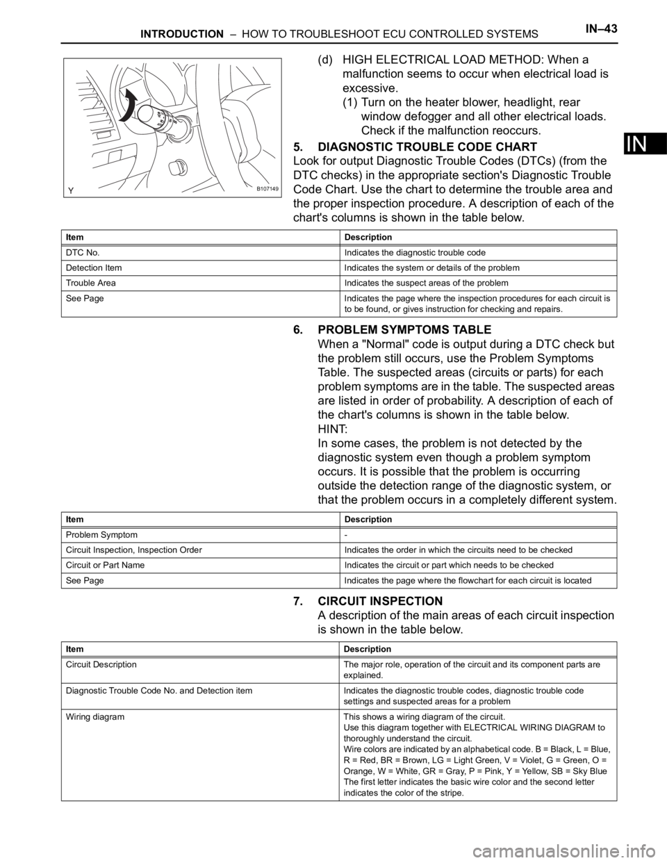
(d) HIGH ELECTRICAL LOAD METHOD: When a
malfunction seems to occur when electrical load is
excessive.
(1) Turn on the heater blower, headlight, rear
window defogger and all other electrical loads.
Check if the malfunction reoccurs.
5. DIAGNOSTIC TROUBLE CODE CHART
Look for output Diagnostic Trouble Codes (DTCs) (from the
DTC checks) in the appropriate section's Diagnostic Trouble
Code Chart. Use the chart to determine the trouble area and
the proper inspection procedure. A description of each of the
chart's columns is shown in the table below.
6. PROBLEM SYMPTOMS TABLE
When a "Normal" code is output during a DTC check but
the problem still occurs, use the Problem Symptoms
Table. The suspected areas (circuits or parts) for each
problem symptoms are in the table. The suspected areas
are listed in order of probability. A description of each of
the chart's columns is shown in the table below.
HINT:
In some cases, the problem is not detected by the
diagnostic system even though a problem symptom
occurs. It is possible that the problem is occurring
outside the detection range of the diagnostic system, or
that the problem occurs in a completely different system.
7. CIRCUIT INSPECTION
A description of the main areas of each circuit inspection
is shown in the table below.
B107149
Item Description
DTC No. Indicates the diagnostic trouble code
Detection Item Indicates the system or details of the problem
Trouble Area Indicates the suspect areas of the problem
See Page Indicates the page where the inspection procedures for each circuit is
to be found, or gives instruction for checking and repairs.
Item Description
Problem Symptom -
Circuit Inspection, Inspection Order Indicates the order in which the circuits need to be checked
Circuit or Part Name Indicates the circuit or part which needs to be checked
See Page Indicates the page where the flowchart for each circuit is located
Item Description
Circuit Description The major role, operation of the circuit and its component parts are
explained.
Diagnostic Trouble Code No. and Detection item Indicates the diagnostic trouble codes, diagnostic trouble code
settings and suspected areas for a problem
Wiring diagram This shows a wiring diagram of the circuit.
Use this diagram together with ELECTRICAL WIRING DIAGRAM to
thoroughly understand the circuit.
Wire colors are indicated by an alphabetical code. B = Black, L = Blue,
R = Red, BR = Brown, LG = Light Green, V = Violet, G = Green, O =
Orange, W = White, GR = Gray, P = Pink, Y = Yellow, SB = Sky Blue
The first letter indicates the basic wire color and the second letter
indicates the color of the stripe.
Page 127 of 3000

PP–14PREPARATION – 2GR-FE COOLING
PP
EQUIPMENT
Ohmmeter -
Radiator cap tester -
Thermometer -
To r q u e w r e n c h -
Slide calipers -
Heater -
Ammeter (A) -
Page 283 of 3000
WS–66WINDSHIELD / WINDOWGLASS – WINDOW DEFOGGER SYSTEM
WS
PROBLEM SYMPTOMS TABLE
WINDOW DEFOGGER SYSTEM
ON-VEHICLE INSPECTION
1. INSPECT BACK WINDOW (DEFOGGER WIRE)
NOTICE:
• When cleaning the glass, wipe the glass along the
wire using a soft and dry cloth. Take care not to
damage the wires.
• Do not use detergents or glass cleaners including
abrasive ingredients.
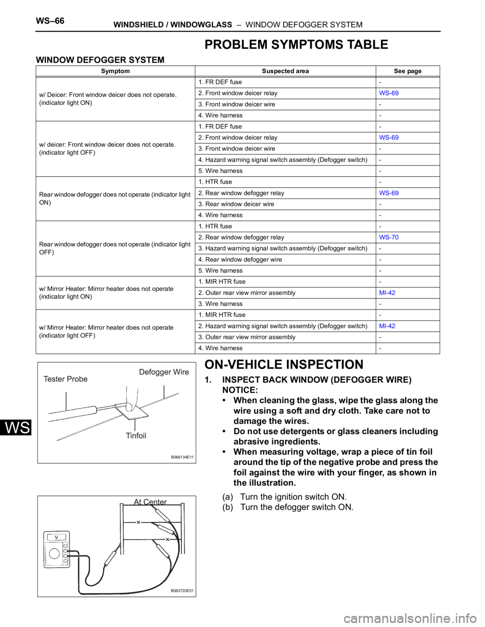
• When measuring voltage, wrap a piece of tin foil
around the tip of the negative probe and press the
foil against the wire with your finger, as shown in
the illustration.
(a) Turn the ignition switch ON.
(b) Turn the defogger switch ON.
Symptom Suspected area See page
w/ Deicer: Front window deicer does not operate.
(indicator light ON)1. FR DEF fuse -
2. Front window deicer relayWS-69
3. Front window deicer wire -
4. Wire harness -
w/ deicer: Front window deicer does not operate.
(indicator light OFF)1. FR DEF fuse -
2. Front window deicer relayWS-69
3. Front window deicer wire -
4. Hazard warning signal switch assembly (Defogger switch) -
5. Wire harness -
Rear window defogger does not operate (indicator light
ON)1. HTR fuse -
2. Rear window defogger relayWS-69
3. Rear window deicer wire -
4. Wire harness -
Rear window defogger does not operate (indicator light
OFF)1. HTR fuse -
2. Rear window defogger relayWS-70
3. Hazard warning signal switch assembly (Defogger switch) -
4. Rear window defogger wire -
5. Wire harness -
w/ Mirror Heater: Mirror heater does not operate
(indicator light ON)1. MIR HTR fuse -
2. Outer rear view mirror assemblyMI-42
3. Wire harness -
w/ Mirror Heater: Mirror heater does not operate
(indicator light OFF)1. MIR HTR fuse -
2. Hazard warning signal switch assembly (Defogger switch)MI-42
3. Outer rear view mirror assembly -
4. Wire harness -
B066134E11
B063720E01
Page 327 of 3000
2GR-FE ENGINE CONTROL SYSTEM – SFI SYSTEMES–259
ES
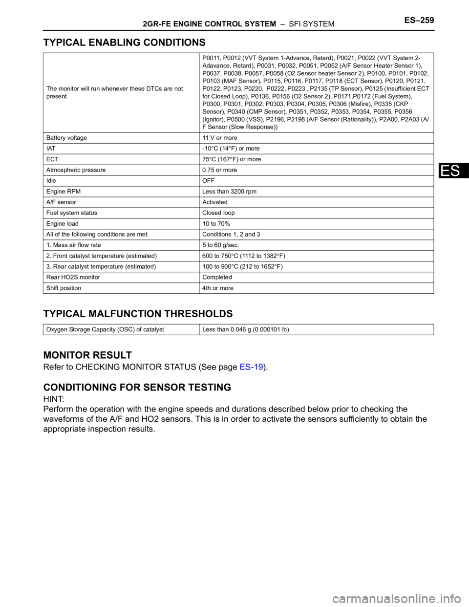
TYPICAL ENABLING CONDITIONS
TYPICAL MALFUNCTION THRESHOLDS
MONITOR RESULT
Refer to CHECKING MONITOR STATUS (See page ES-19).
CONDITIONING FOR SENSOR TESTING
HINT:
Perform the operation with the engine speeds and durations described below prior to checking the
waveforms of the A/F and HO2 sensors. This is in order to activate the sensors sufficiently to obtain the
appropriate inspection results.
The monitor will run whenever these DTCs are not
presentP0011, P0012 (VVT System 1-Advance, Retard), P0021, P0022 (VVT System 2-
Adavance, Retard), P0031, P0032, P0051, P0052 (A/F Sensor Heater Sensor 1),
P0037, P0038, P0057, P0058 (O2 Sensor heater Sensor 2), P0100, P0101, P0102,
P0103 (MAF Sensor), P0115, P0116, P0117, P0118 (ECT Sensor), P0120, P0121,
P0122, P0123, P0220, P0222, P0223 , P2135 (TP Sensor), P0125 (Insufficient ECT
for Closed Loop), P0136, P0156 (O2 Sensor 2), P0171,P0172 (Fuel System),
P0300, P0301, P0302, P0303, P0304, P0305, P0306 (Misfire), P0335 (CKP
Sensor), P0340 (CMP Sensor), P0351, P0352, P0353, P0354, P0355, P0356
(Ignitor), P0500 (VSS), P2196, P2198 (A/F Sensor (Rationality)), P2A00, P2A03 (A/
F Sensor (Slow Response))
Battery voltage 11 V or more
IAT -10
C (14F) or more
ECT 75
C (167F) or more
Atmospheric pressure 0.75 or more
Idle OFF
Engine RPM Less than 3200 rpm
A/F sensor Activated
Fuel system status Closed loop
Engine load 10 to 70%
All of the following conditions are met Conditions 1, 2 and 3
1. Mass air flow rate 5 to 60 g/sec.
2. Front catalyst temperature (estimated) 600 to 750
C (1112 to 1382F)
3. Rear catalyst temperature (estimated) 100 to 900
C (212 to 1652F)
Rear HO2S monitor Completed
Shift position 4th or more
Oxygen Storage Capacity (OSC) of catalyst Less than 0.046 g (0.000101 lb)
Page 330 of 3000
ES–2622GR-FE ENGINE CONTROL SYSTEM – SFI SYSTEM
ES
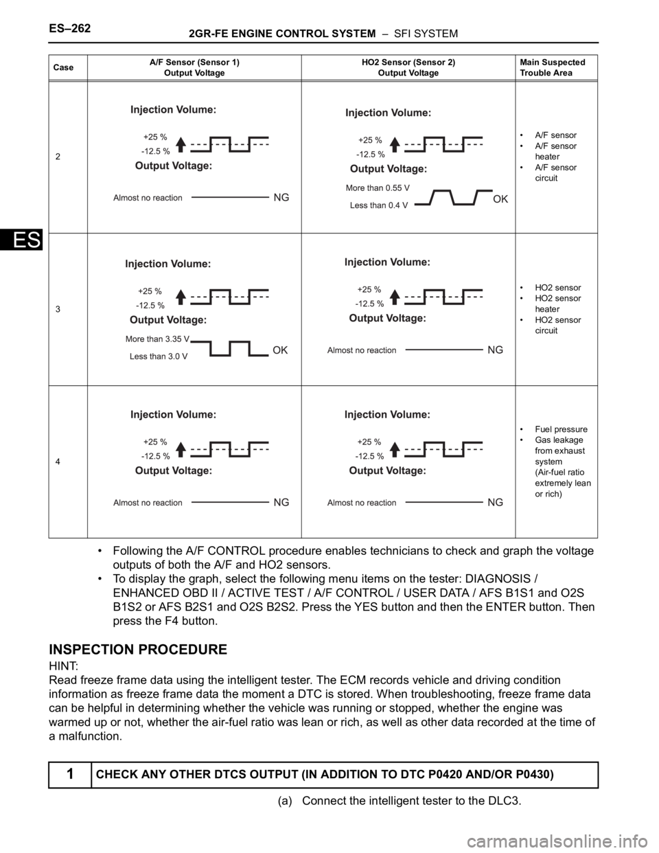
• Following the A/F CONTROL procedure enables technicians to check and graph the voltage
outputs of both the A/F and HO2 sensors.
• To display the graph, select the following menu items on the tester: DIAGNOSIS /
ENHANCED OBD II / ACTIVE TEST / A/F CONTROL / USER DATA / AFS B1S1 and O2S
B1S2 or AFS B2S1 and O2S B2S2. Press the YES button and then the ENTER button. Then
press the F4 button.
INSPECTION PROCEDURE
HINT:
Read freeze frame data using the intelligent tester. The ECM records vehicle and driving condition
information as freeze frame data the moment a DTC is stored. When troubleshooting, freeze frame data
can be helpful in determining whether the vehicle was running or stopped, whether the engine was
warmed up or not, whether the air-fuel ratio was lean or rich, as well as other data recorded at the time of
a malfunction.
(a) Connect the intelligent tester to the DLC3.
2• A/F sensor
• A/F sensor
heater
• A/F sensor
circuit
3• HO2 sensor
• HO2 sensor
heater
• HO2 sensor
circuit
4•Fuel pressure
• Gas leakage
from exhaust
system
(Air-fuel ratio
extremely lean
or rich)
1CHECK ANY OTHER DTCS OUTPUT (IN ADDITION TO DTC P0420 AND/OR P0430)
CaseA/F Sensor (Sensor 1)
Output VoltageHO2 Sensor (Sensor 2)
Output VoltageMain Suspected
Trouble Area
Page 351 of 3000

2GR-FE ENGINE CONTROL SYSTEM – SFI SYSTEMES–25
ES
Rear Oxygen Sensor Heater
$A7 $0C Multiply by 1 TimeMisfire rate for cylinder 6: Misfire counts for last/current driving cycle-
To t a l
Monitor ID Test ID Scaling Unit Description
$42 $91 Multiply by 0.001 Ohm Oxygen sensor heater resistance bank 1 sensor 2
$46 $91 Multiply by 0.004 Ohm Oxygen sensor heater resistance bank 2 sensor 2 Monitor ID Test ID Scaling Unit Description