roof TOYOTA SIENNA 2007 Service Repair Manual
[x] Cancel search | Manufacturer: TOYOTA, Model Year: 2007, Model line: SIENNA, Model: TOYOTA SIENNA 2007Pages: 3000, PDF Size: 52.26 MB
Page 51 of 3000

INTRODUCTION – HOW TO TROUBLESHOOT ECU CONTROLLED SYSTEMSIN–39
IN
• In the DTC check, it is very important to determine
whether the problem indicated by the DTC either: 1)
still occurs, or 2) occurred in the past but has returned
to normal. In addition, the DTC should be compared
to the problem symptom to see if they are related. For
this reason, DTCs should be checked before and after
confirmation of symptoms (i.e., whether or not
problem symptoms exist) to determine current system
conditions, as shown in the flowchart below.
• Never skip the DTC check. Failing to check DTCs
may, depending on the case, result in unnecessary
troubleshooting for systems operating normally or
lead to repairs not related to the problem. Follow the
procedures listed in the flowchart in the correct order.
Theft Deterrent System XXXXX
Engine Immobiliser System
XX
Cruise Control SystemXXX
Dynamic Laser Cruise Control System
XXX
Lighting System
XX
Wiper and Washer SystemXXXXX
Power Door Lock Control System X X X
Wireless Door Lock Control SystemXX
Key Reminder Warning System X X XX
Meter / Gauge System X X X
Audio and Visual SystemXXXX
Rear Seat Entertainment System XXXXX
Navigation System
XXXX
Clearance Sonar SystemXXXXX
Rear View Monitor System XXXXX
Power Window Control System (with Jam
Protection Function)XXX
Power Window Control System (without Jam
Protection Function)XXXXX
Power Mirror Control System (with Memory) X X X
Power Mirror Control System (without Memory)XXXXX
Front Power Seat Control System X X X
Rear No. 2 Seat Assembly (with Power Stowing
Function)XXXXX
Window Deogger SystemXXXXX
Power Slide Door System
XX
Slide Door Closer System X X X
Back Door Closer SystemXX
Power Back Door SystemXX
Sliding Roof System XXXXX
Multiplex Communication System XXXXX
CAN Communication System XXXXXSystemSYMPTOM CONFIRMATION AND DIAGNOSTIC TROUBLE CODE
DTC Check
(Normal Mode)DTC Check
(Check Mode)Sensor Check/
Test Mode
(Input Signal
Check)Data List Active Test
Page 61 of 3000

INTRODUCTION – HOW TO TROUBLESHOOT ECU CONTROLLED SYSTEMSIN–31
IN
ELECTRONIC CIRCUIT INSPECTION
PROCEDURE
1. BASIC INSPECTION
(a) WHEN MEASURING RESISTANCE OF
ELECTRONIC PARTS
(1) Unless otherwise stated, all resistance
measurements should be made at an ambient
temperature of 20
C (68F). Resistance
measurements may be inaccurate if measured
at high temperatures, i.e. immediately after the
vehicle has been running. Measurements should
be made after the engine has cooled down.
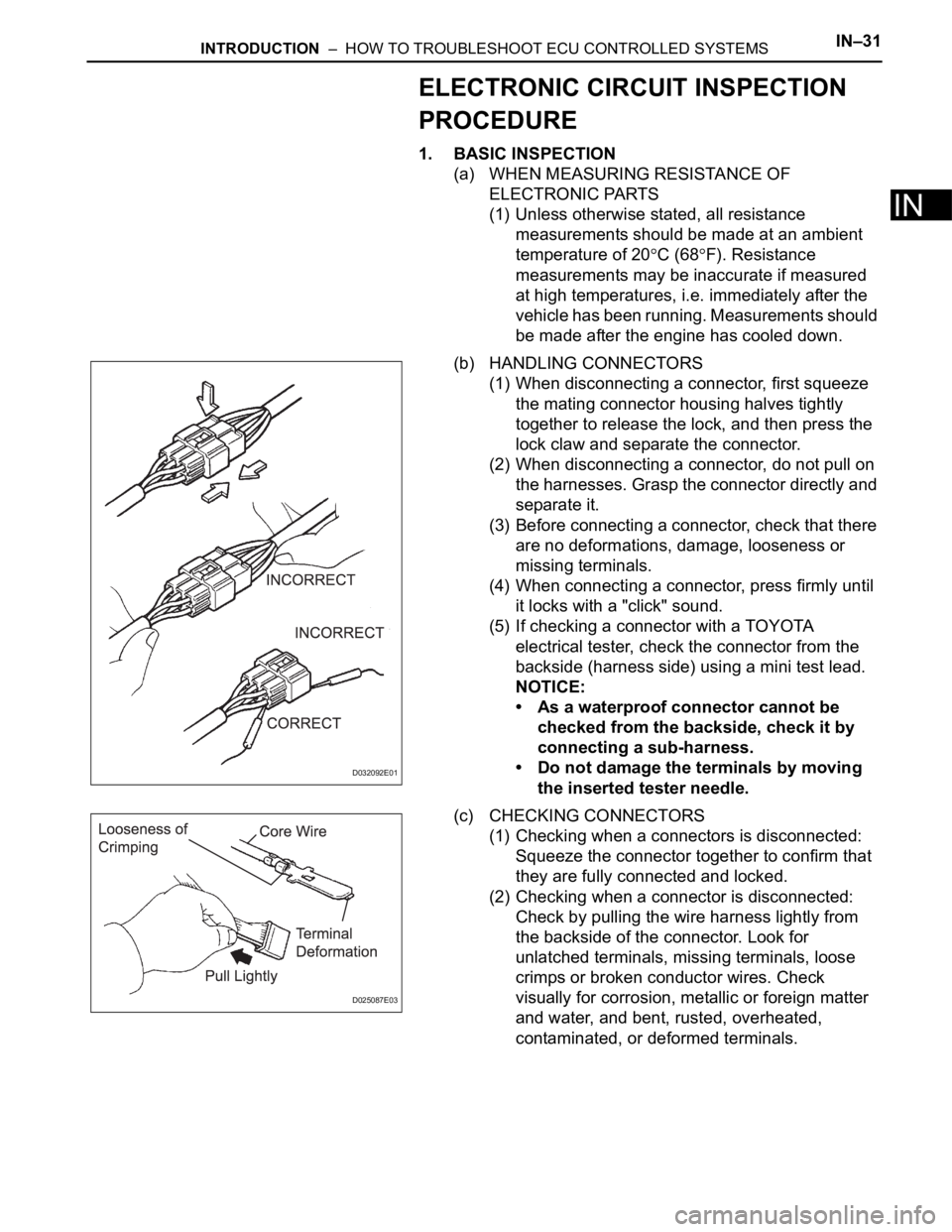
(b) HANDLING CONNECTORS
(1) When disconnecting a connector, first squeeze
the mating connector housing halves tightly
together to release the lock, and then press the
lock claw and separate the connector.
(2) When disconnecting a connector, do not pull on
the harnesses. Grasp the connector directly and
separate it.
(3) Before connecting a connector, check that there
are no deformations, damage, looseness or
missing terminals.
(4) When connecting a connector, press firmly until
it locks with a "click" sound.
(5) If checking a connector with a TOYOTA
electrical tester, check the connector from the
backside (harness side) using a mini test lead.
NOTICE:
• As a waterproof connector cannot be
checked from the backside, check it by
connecting a sub-harness.
• Do not damage the terminals by moving
the inserted tester needle.
(c) CHECKING CONNECTORS
(1) Checking when a connectors is disconnected:
Squeeze the connector together to confirm that
they are fully connected and locked.
(2) Checking when a connector is disconnected:
Check by pulling the wire harness lightly from
the backside of the connector. Look for
unlatched terminals, missing terminals, loose
crimps or broken conductor wires. Check
visually for corrosion, metallic or foreign matter
and water, and bent, rusted, overheated,
contaminated, or deformed terminals.
D032092E01
D025087E03
Page 69 of 3000

INTRODUCTION – HOW TO TROUBLESHOOT ECU CONTROLLED SYSTEMSIN–39
IN
• In the DTC check, it is very important to determine
whether the problem indicated by the DTC either: 1)
still occurs, or 2) occurred in the past but has returned
to normal. In addition, the DTC should be compared
to the problem symptom to see if they are related. For
this reason, DTCs should be checked before and after
confirmation of symptoms (i.e., whether or not
problem symptoms exist) to determine current system
conditions, as shown in the flowchart below.
• Never skip the DTC check. Failing to check DTCs
may, depending on the case, result in unnecessary
troubleshooting for systems operating normally or
lead to repairs not related to the problem. Follow the
procedures listed in the flowchart in the correct order.
Theft Deterrent System XXXXX
Engine Immobiliser System
XX
Cruise Control SystemXXX
Dynamic Laser Cruise Control System
XXX
Lighting System
XX
Wiper and Washer SystemXXXXX
Power Door Lock Control System X X X
Wireless Door Lock Control SystemXX
Key Reminder Warning System X X XX
Meter / Gauge System X X X
Audio and Visual SystemXXXX
Rear Seat Entertainment System XXXXX
Navigation System
XXXX
Clearance Sonar SystemXXXXX
Rear View Monitor System XXXXX
Power Window Control System (with Jam
Protection Function)XXX
Power Window Control System (without Jam
Protection Function)XXXXX
Power Mirror Control System (with Memory) X X X
Power Mirror Control System (without Memory)XXXXX
Front Power Seat Control System X X X
Rear No. 2 Seat Assembly (with Power Stowing
Function)XXXXX
Window Deogger SystemXXXXX
Power Slide Door System
XX
Slide Door Closer System X X X
Back Door Closer SystemXX
Power Back Door SystemXX
Sliding Roof System XXXXX
Multiplex Communication System XXXXX
CAN Communication System XXXXXSystemSYMPTOM CONFIRMATION AND DIAGNOSTIC TROUBLE CODE
DTC Check
(Normal Mode)DTC Check
(Check Mode)Sensor Check/
Test Mode
(Input Signal
Check)Data List Active Test
Page 845 of 3000

SLIDING ROOF – SLIDING ROOF SYSTEMRF–3
RF
INITIALIZATION
1. RESET SLIDING ROOF MOTOR
(a) If the AUTO operation function does not operate,
reset the sliding roof motor using any of the
following methods.
(1) Press the sliding roof switch on the TILT UP side
and hold it until the sliding roof motor stops.
Then release the switch and leave it untouched
for 10 seconds or more.
(2) Press the sliding roof switch on the TILT UP side
again for 10 seconds or more and hold it until the
sliding roof stops at the fully open and up
position.
(3) Release the switch, press it again within 5
seconds and hold it until a series of movements
indicated below has done:
Fully closing
Fully opening Fully closing
HINT:
If the battery terminal is disconnected or after
the jam protection function has operated, the
sliding roof ECU may not detect a position of the
roof glass. If the AUTO operation function is still
disabled even if the sliding roof motor has been
reset, the Hall IC (built in the sliding roof motor
assembly) for detecting the roof glass position
may be malfunctioning.
Page 846 of 3000

RF–4SLIDING ROOF – SLIDING ROOF SYSTEM
RF
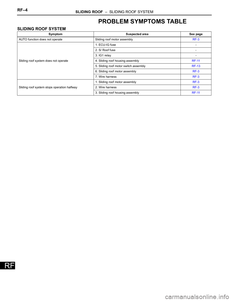
PROBLEM SYMPTOMS TABLE
SLIDING ROOF SYSTEM
Symptom Suspected area See page
AUTO function does not operate Sliding roof motor assemblyRF-3
Sliding roof system does not operate1. ECU-IG fuse -
2. S/ Roof fuse -
3. IG1 relay -
4. Sliding roof housing assemblyRF-11
5. Sliding roof motor switch assemblyRF-13
6. Sliding roof motor assemblyRF-3
7. Wire harnessRF-3
Sliding roof system stops operation halfway1. Sliding roof motor assemblyRF-3
2. Wire harnessRF-3
3. Sliding roof housing assemblyRF-11
Page 2331 of 3000

TW–82TIRE AND WHEEL – TIRE PRESSURE WARNING RECEIVER (w/ Antenna)
TW
REMOVAL
1. DISCONNECT CABLE FROM NEGATIVE BATTERY
TERMINAL
2. REMOVE ROOF HEADLINING ASSEMBLY
HINT:
Refer to the instructions for REMOVAL of the ROOF
HEADLINING (See page IR-6).
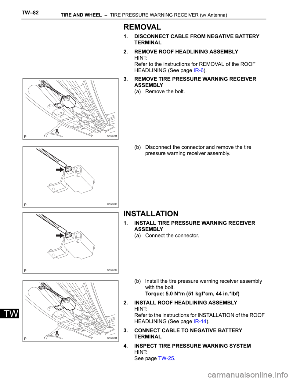
3. REMOVE TIRE PRESSURE WARNING RECEIVER
ASSEMBLY
(a) Remove the bolt.
(b) Disconnect the connector and remove the tire
pressure warning receiver assembly.
INSTALLATION
1. INSTALL TIRE PRESSURE WARNING RECEIVER
ASSEMBLY
(a) Connect the connector.
(b) Install the tire pressure warning receiver assembly
with the bolt.
Torque: 5.0 N*m (51 kgf*cm, 44 in.*lbf)
2. INSTALL ROOF HEADLINING ASSEMBLY
HINT:
Refer to the instructions for INSTALLATION of the ROOF
HEADLINING (See page IR-14).
3. CONNECT CABLE TO NEGATIVE BATTERY
TERMINAL
4. INSPECT TIRE PRESSURE WARNING SYSTEM
HINT:
See page TW-25.
C156704
C156705
C156705
C156704
Page 2942 of 3000

AC–204AIR CONDITIONING – BLOWER UNIT (for Rear Air Conditioning System)
AC
REMOVAL
1. DISCHARGE REFRIGERANT FROM
REFRIGERATION SYSTEM
SST 07110-58060 (07117-58080, 07117-58090,
07117-78050, 07117-88060, 07117-88070,
07117-88080)
HINT:
See page AC-172.
2. REMOVE REAR DOOR SCUFF PLATE RH (See page
IR-7)
3. REMOVE BACK DOOR SCUFF PLATE (See page IR-
8)
4. REMOVE QUARTER TRIM PANEL ASSEMBLY
FRONT RH (See page IR-9)
5. REMOVE ROOF HEADLINING GARNISH REAR (See
page IR-9)
6. REMOVE RR WINDOW SIDE GARNISH ASSEMBLY
NO.2 RH (See page IR-9)
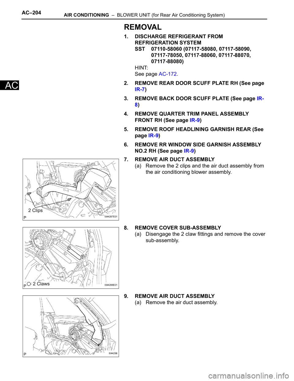
7. REMOVE AIR DUCT ASSEMBLY
(a) Remove the 2 clips and the air duct assembly from
the air conditioning blower assembly.
8. REMOVE COVER SUB-ASSEMBLY
(a) Disengage the 2 claw fittings and remove the cover
sub-assembly.
9. REMOVE AIR DUCT ASSEMBLY
(a) Remove the air duct assembly.
I044287E01
I044288E01
I044296