wheel torque TOYOTA SIENNA 2007 Service Repair Manual
[x] Cancel search | Manufacturer: TOYOTA, Model Year: 2007, Model line: SIENNA, Model: TOYOTA SIENNA 2007Pages: 3000, PDF Size: 52.26 MB
Page 16 of 3000

SS–30SERVICE SPECIFICATIONS – U151E AUTOMATIC TRANSAXLE
SS
TORQUE SPECIFICATIONS
Part Tightened N*m kgf*cm ft*lbf
Park/neutral position switch Nut 6.9 70 61 in.*lbf
Bolt 5.4 55 48 in.*lbf
Control shaft lever x Control shaft 13 130 9
Shift control cable x Control shaft lever 13 130 9
Transaxle housing x Engine block A bolt 64 653 47
B bolt 46 470 34
C bolt 43 439 32
Torque converter clutch x Drive plate 41 413 35
Flywheel housing under cover x Automatic transaxle 7.8 80 69 in.*lbf
Engine mounting bracket FR x Transaxle 64 653 47
Oil filler tube x Transaxle5.5 56 49 in.*lbf
Control cable bracket No. 1 x Transaxle 12 122 9
Control cable bracket No. 2 x Transaxle 12 122 9
Oil cooler tube clamp x Control cable bracket 5.5 56 49 in.*lbf
Oil cooler inlet tube x Transaxle27 275 20
Oil cooler outlet tube x Transaxle 27 275 20
Starter x Transaxle37 377 27
Starter wire x Starter9.8 100 87 in.*lbf
Wire harness x Transaxle13 133 10
Wire harness clamp x Transaxle8.4 86 74 in.*lbf
Speed sensor (NC) x Transaxle11 11 5 8
Speed sensor (NT) x Transaxle11 11 2 8
Air cleaner x Air cleaner hose5.0 51 44 in.*lbf
Drain plug x Oil pan49 500 36
Transmission wire x Transaxle5.4 55 48 in.*lbf
ATF temperature sensor x Valve body 6.6 67 58 in.*lbf
Oil pan x Transaxle7.8 80 69 in.*lbf
Solenoid valve x Valve body A B bolt 11 110 8
C D bolt 6.6 67 58 in.*lbf
Valve body x Transaxle11 11 0 8
Oil strainer x Valve body11 11 0 8
Floor shift assembly x Body21 214 15
Control cable x Body12 122 9
Engine mount bracket RR x Transfer stiffener plate RH 34 350 25
Oil cooler assembly x Body Nut
7.0 71 62 in.*lbf
bolt
Differential gear lube apply tube x Transaxle housing 9.8 100 87 in.*lbf
Front planetary gear lock nut
210 to 3502,141 to
3,569155 to 258
Brake apply tube clamp x Transaxle case 5.4 55 48 in.*lbf
Transaxle case No. 1 plug x Transaxle rear cover 7.4 75 65 in.*lbf
Transaxle rear cover x Transaxle case Bolt A 19 190 14
Other bolt 25 250 18
Pawl shaft clamp x Transaxle case 9.8 100 87 in.*lbf
Oil pump assembly x Transaxle case 22 226 16
Page 92 of 3000
U151E AUTOMATIC TRANSAXLE – AUTOMATIC TRANSAXLE ASSEMBLYAX–165
AX
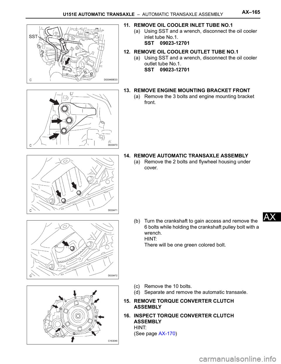
11. REMOVE OIL COOLER INLET TUBE NO.1
(a) Using SST and a wrench, disconnect the oil cooler
inlet tube No.1.
SST 09023-12701
12. REMOVE OIL COOLER OUTLET TUBE NO.1
(a) Using SST and a wrench, disconnect the oil cooler
outlet tube No.1.
SST 09023-12701
13. REMOVE ENGINE MOUNTING BRACKET FRONT
(a) Remove the 3 bolts and engine mounting bracket
front.
14. REMOVE AUTOMATIC TRANSAXLE ASSEMBLY
(a) Remove the 2 bolts and flywheel housing under
cover.
(b) Turn the crankshaft to gain access and remove the
6 bolts while holding the crankshaft pulley bolt with a
wrench.
HINT:
There will be one green colored bolt.
(c) Remove the 10 bolts.
(d) Separate and remove the automatic transaxle.
15. REMOVE TORQUE CONVERTER CLUTCH
ASSEMBLY
16. INSPECT TORQUE CONVERTER CLUTCH
ASSEMBLY
HINT:
(See page AX-170)
D030469E03
D030470
D030471
D030472
C163046
Page 94 of 3000
U151E AUTOMATIC TRANSAXLE – AUTOMATIC TRANSAXLE ASSEMBLYAX–167
AX
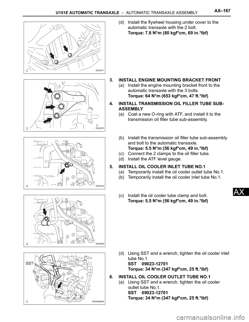
(d) Install the flywheel housing under cover to the
automatic transaxle with the 2 bolt.
Torque: 7.8 N*m (80 kgf*cm, 69 in.*lbf)
3. INSTALL ENGINE MOUNTING BRACKET FRONT
(a) Install the engine mounting bracket front to the
automatic transaxle with the 3 bolts.
Torque: 64 N*m (653 kgf*cm, 47 ft.*lbf)
4. INSTALL TRANSMISSION OIL FILLER TUBE SUB-
ASSEMBLY
(a) Coat a new O-ring with ATF, and install it to the
transmission oil filler tube sub-assembly.
(b) Install the transmission oil filler tube sub-assembly
and bolt to the automatic transaxle.
Torque: 5.5 N*m (56 kgf*cm, 49 in.*lbf)
(c) Connect the 2 clamps to the oil filler tube.
(d) Install the ATF level gauge.
5. INSTALL OIL COOLER INLET TUBE NO.1
(a) Temporarily install the oil cooler outlet tube No.1.
(b) Temporarily install the oil cooler inlet tube No.1.
(c) Install the oil cooler tube clamp and bolt.
Torque: 5.5 N*m (56 kgf*cm, 49 in.*lbf)
(d) Using SST and a wrench, tighten the oil cooler inlet
tube No.1.
SST 09023-12701
Torque: 34 N*m (347 kgf*cm, 25 ft.*lbf)
6. INSTALL OIL COOLER OUTLET TUBE NO.1
(a) Using SST and a wrench, tighten the oil cooler
outlet tube No.1.
SST 09023-12701
Torque: 34 N*m (347 kgf*cm, 25 ft.*lbf)
D030471
D030470
D030700
D030699
D030469E04
Page 104 of 3000
U151F AUTOMATIC TRANSAXLE – AUTOMATIC TRANSAXLE ASSEMBLYAX–169
AX
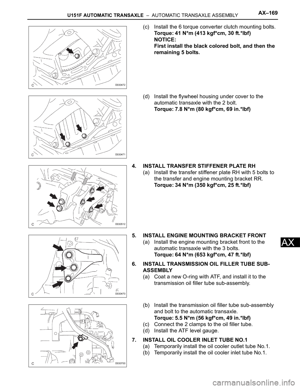
(c) Install the 6 torque converter clutch mounting bolts.
Torque: 41 N*m (413 kgf*cm, 30 ft.*lbf)
NOTICE:
First install the black colored bolt, and then the
remaining 5 bolts.
(d) Install the flywheel housing under cover to the
automatic transaxle with the 2 bolt.
Torque: 7.8 N*m (80 kgf*cm, 69 in.*lbf)
4. INSTALL TRANSFER STIFFENER PLATE RH
(a) Install the transfer stiffener plate RH with 5 bolts to
the transfer and engine mounting bracket RR.
Torque: 34 N*m (350 kgf*cm, 25 ft.*lbf)
5. INSTALL ENGINE MOUNTING BRACKET FRONT
(a) Install the engine mounting bracket front to the
automatic transaxle with the 3 bolts.
Torque: 64 N*m (653 kgf*cm, 47 ft.*lbf)
6. INSTALL TRANSMISSION OIL FILLER TUBE SUB-
ASSEMBLY
(a) Coat a new O-ring with ATF, and install it to the
transmission oil filler tube sub-assembly.
(b) Install the transmission oil filler tube sub-assembly
and bolt to the automatic transaxle.
Torque: 5.5 N*m (56 kgf*cm, 49 in.*lbf)
(c) Connect the 2 clamps to the oil filler tube.
(d) Install the ATF level gauge.
7. INSTALL OIL COOLER INLET TUBE NO.1
(a) Temporarily install the oil cooler outlet tube No.1.
(b) Temporarily install the oil cooler inlet tube No.1.
D030472
D030471
D030512
D030470
D030700
Page 108 of 3000
TF–10TRANSFER – TRANSFER ASSEMBLY
TF
6. INSTALL NO. 1 TRANSFER CASE PLUG
(a) Add oil up to 0 to 5 mm below the lower side of the
plug hole.
Oil quantity:
0.9 L (0.95 US qts, 0.71 lmp. qts)
HINT:
When adding oil, pour it slowly.
(b) Install the No. 1 transfer case plug with a new No. 1
gasket.
Torque: 49 N*m (500 kgf*cm, 36 ft.*lbf)
7. INSPECT AND ADJUST FRONT WHEEL ALIGNMENT
HINT:
(See page SP-4)
8. CHECK ABS SPEED SENSOR SIGNAL
HINT:
(See page BC-3)
Page 110 of 3000
DRIVE SHAFT – FRONT DRIVE SHAFTDS–5
DS
REMOVAL
1. DRAIN AUTOMATIC TRANSAXLE FLUID
(a) Remove the drain plug, gasket and drain ATF.
(b) Install a new gasket and the drain plug.
Torque: 49 N*m (500 kgf*cm, 36 ft.*lbf)
2. DRAIN TRANSFER OIL (for 4WD)
HINT:
(See page TF-8)
3. REMOVE FRONT WHEEL
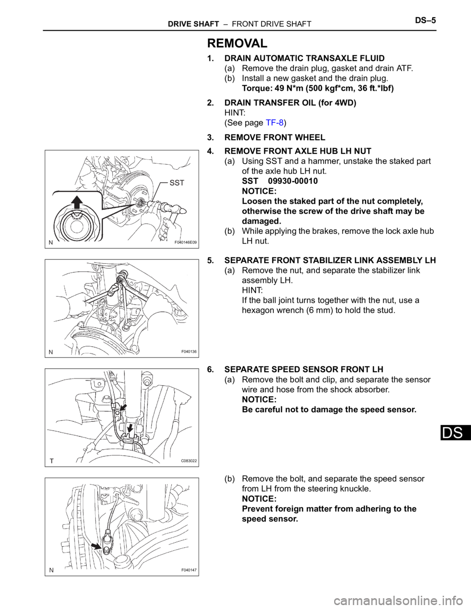
4. REMOVE FRONT AXLE HUB LH NUT
(a) Using SST and a hammer, unstake the staked part
of the axle hub LH nut.
SST 09930-00010
NOTICE:
Loosen the staked part of the nut completely,
otherwise the screw of the drive shaft may be
damaged.
(b) While applying the brakes, remove the lock axle hub
LH nut.
5. SEPARATE FRONT STABILIZER LINK ASSEMBLY LH
(a) Remove the nut, and separate the stabilizer link
assembly LH.
HINT:
If the ball joint turns together with the nut, use a
hexagon wrench (6 mm) to hold the stud.
6. SEPARATE SPEED SENSOR FRONT LH
(a) Remove the bolt and clip, and separate the sensor
wire and hose from the shock absorber.
NOTICE:
Be careful not to damage the speed sensor.
(b) Remove the bolt, and separate the speed sensor
from LH from the steering knuckle.
NOTICE:
Prevent foreign matter from adhering to the
speed sensor.
F040146E09
F040136
C083022
F040147
Page 157 of 3000

PREPARATION – SUPPLEMENTAL RESTRAINT SYSTEMPP–67
PP
EQUIPMENT
Torque wrench
Feeler gauge
Bolt
Length: 35.0 mm (1.378 in.)
Diameter: 6.0mm (0.236 in.)
Pitch: 1.0 mm (0.039 in.)Airbag disposal
Tire
Width: 185mm (7.28 in.)
Inner diameter: 360mm (14.17 in.)Airbag disposal
Tire with disc wheel
Width: 185 mm (7.28 in.)
Inner diameter: 360mm (14.17 in.)Airbag disposal
Plastic bag Airbag disposal
Page 166 of 3000
AXLE – FRONT AXLE HUBAH–9
AH
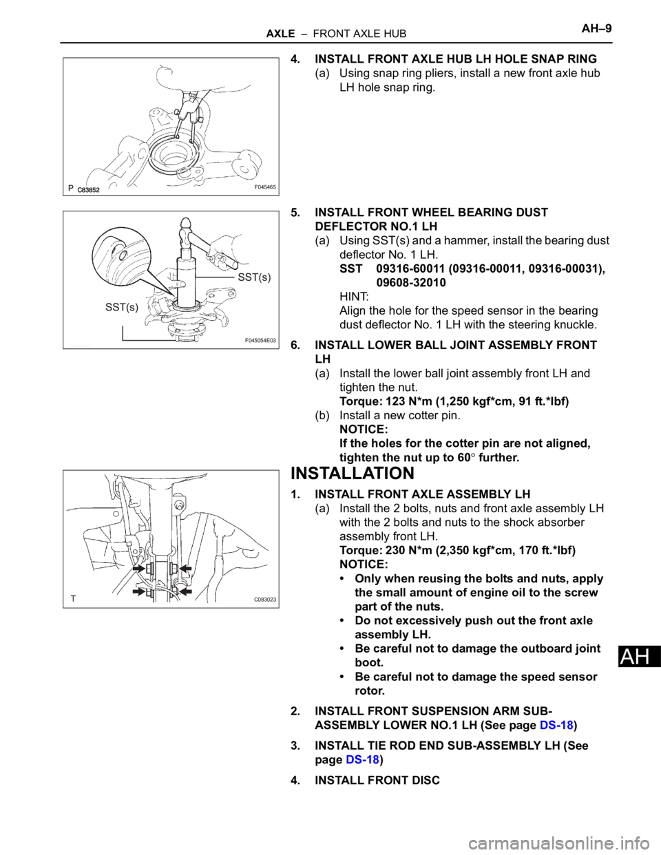
4. INSTALL FRONT AXLE HUB LH HOLE SNAP RING
(a) Using snap ring pliers, install a new front axle hub
LH hole snap ring.
5. INSTALL FRONT WHEEL BEARING DUST
DEFLECTOR NO.1 LH
(a) Using SST(s) and a hammer, install the bearing dust
deflector No. 1 LH.
SST 09316-60011 (09316-00011, 09316-00031),
09608-32010
HINT:
Align the hole for the speed sensor in the bearing
dust deflector No. 1 LH with the steering knuckle.
6. INSTALL LOWER BALL JOINT ASSEMBLY FRONT
LH
(a) Install the lower ball joint assembly front LH and
tighten the nut.
Torque: 123 N*m (1,250 kgf*cm, 91 ft.*lbf)
(b) Install a new cotter pin.
NOTICE:
If the holes for the cotter pin are not aligned,
tighten the nut up to 60
further.
INSTALLATION
1. INSTALL FRONT AXLE ASSEMBLY LH
(a) Install the 2 bolts, nuts and front axle assembly LH
with the 2 bolts and nuts to the shock absorber
assembly front LH.
Torque: 230 N*m (2,350 kgf*cm, 170 ft.*lbf)
NOTICE:
• Only when reusing the bolts and nuts, apply
the small amount of engine oil to the screw
part of the nuts.
• Do not excessively push out the front axle
assembly LH.
• Be careful not to damage the outboard joint
boot.
• Be careful not to damage the speed sensor
rotor.
2. INSTALL FRONT SUSPENSION ARM SUB-
ASSEMBLY LOWER NO.1 LH (See page DS-18)
3. INSTALL TIE ROD END SUB-ASSEMBLY LH (See
page DS-18)
4. INSTALL FRONT DISC
F045465
F045054E03
C083023
Page 167 of 3000
AH–10AXLE – FRONT AXLE HUB
AH
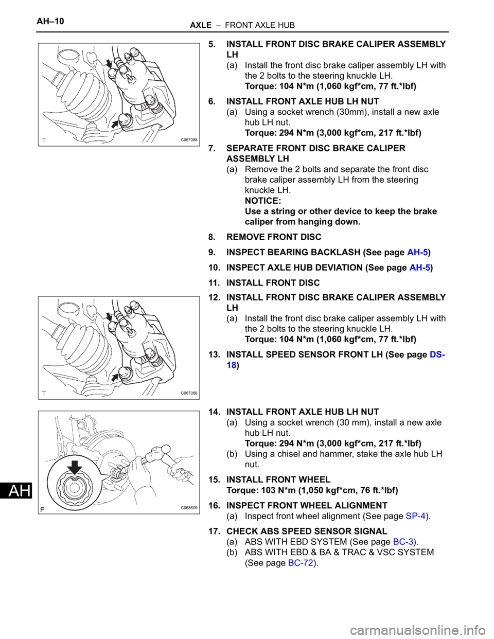
5. INSTALL FRONT DISC BRAKE CALIPER ASSEMBLY
LH
(a) Install the front disc brake caliper assembly LH with
the 2 bolts to the steering knuckle LH.
Torque: 104 N*m (1,060 kgf*cm, 77 ft.*lbf)
6. INSTALL FRONT AXLE HUB LH NUT
(a) Using a socket wrench (30mm), install a new axle
hub LH nut.
Torque: 294 N*m (3,000 kgf*cm, 217 ft.*lbf)
7. SEPARATE FRONT DISC BRAKE CALIPER
ASSEMBLY LH
(a) Remove the 2 bolts and separate the front disc
brake caliper assembly LH from the steering
knuckle LH.
NOTICE:
Use a string or other device to keep the brake
caliper from hanging down.
8. REMOVE FRONT DISC
9. INSPECT BEARING BACKLASH (See page AH-5)
10. INSPECT AXLE HUB DEVIATION (See page AH-5)
11. INSTALL FRONT DISC
12. INSTALL FRONT DISC BRAKE CALIPER ASSEMBLY
LH
(a) Install the front disc brake caliper assembly LH with
the 2 bolts to the steering knuckle LH.
Torque: 104 N*m (1,060 kgf*cm, 77 ft.*lbf)
13. INSTALL SPEED SENSOR FRONT LH (See page DS-
18)
14. INSTALL FRONT AXLE HUB LH NUT
(a) Using a socket wrench (30 mm), install a new axle
hub LH nut.
Torque: 294 N*m (3,000 kgf*cm, 217 ft.*lbf)
(b) Using a chisel and hammer, stake the axle hub LH
nut.
15. INSTALL FRONT WHEEL
Torque: 103 N*m (1,050 kgf*cm, 76 ft.*lbf)
16. INSPECT FRONT WHEEL ALIGNMENT
(a) Inspect front wheel alignment (See page SP-4).
17. CHECK ABS SPEED SENSOR SIGNAL
(a) ABS WITH EBD SYSTEM (See page BC-3).
(b) ABS WITH EBD & BA & TRAC & VSC SYSTEM
(See page BC-72).
C067088
C067088
C068609
Page 171 of 3000
SUSPENSION – REAR SHOCK ABSORBERSP–53
SP
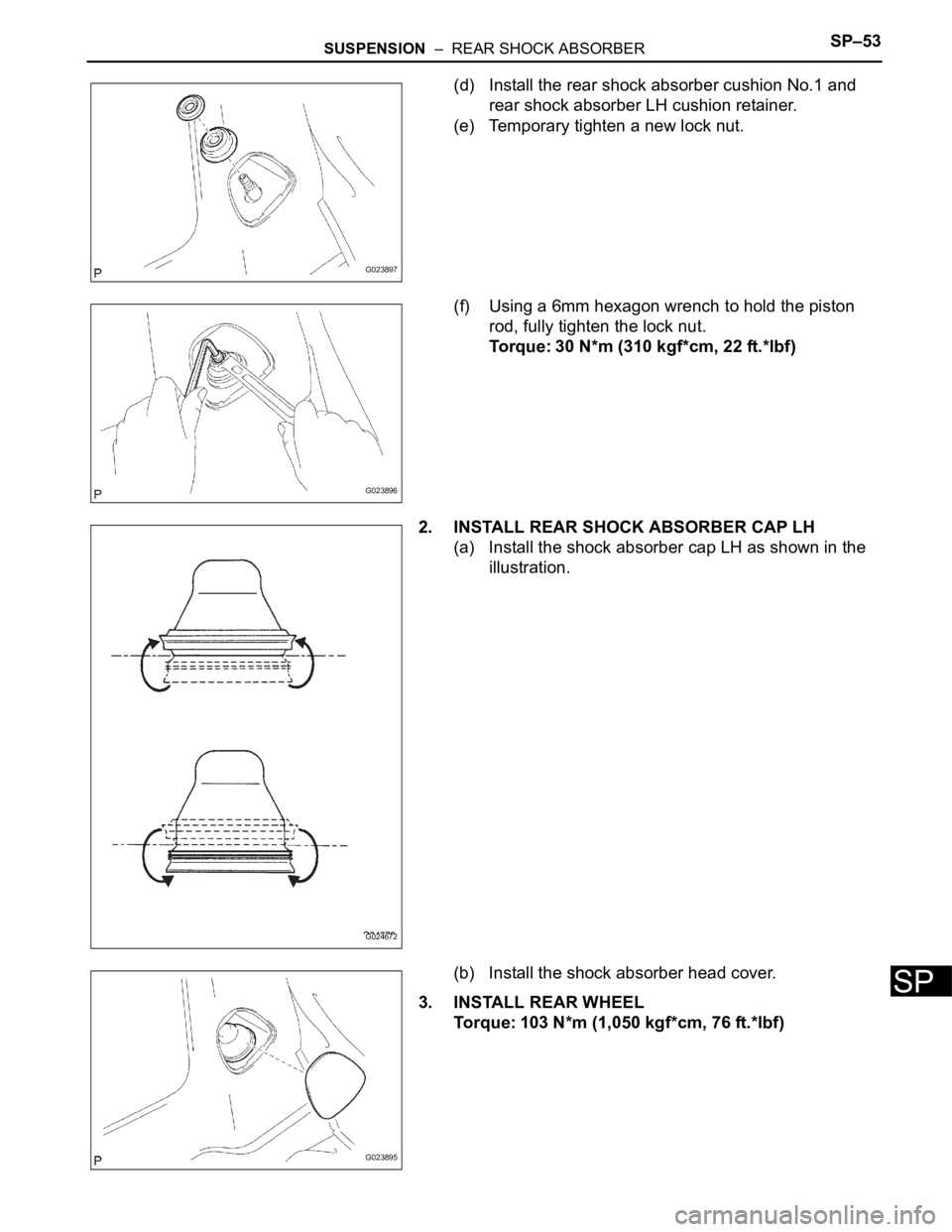
(d) Install the rear shock absorber cushion No.1 and
rear shock absorber LH cushion retainer.
(e) Temporary tighten a new lock nut.
(f) Using a 6mm hexagon wrench to hold the piston
rod, fully tighten the lock nut.
Torque: 30 N*m (310 kgf*cm, 22 ft.*lbf)
2. INSTALL REAR SHOCK ABSORBER CAP LH
(a) Install the shock absorber cap LH as shown in the
illustration.
(b) Install the shock absorber head cover.
3. INSTALL REAR WHEEL
Torque: 103 N*m (1,050 kgf*cm, 76 ft.*lbf)
G023897
G023896
G024672
G023895