fuse diagram TOYOTA SUPRA 1986 Service Repair Manual
[x] Cancel search | Manufacturer: TOYOTA, Model Year: 1986, Model line: SUPRA, Model: TOYOTA SUPRA 1986Pages: 878, PDF Size: 20 MB
Page 73 of 878
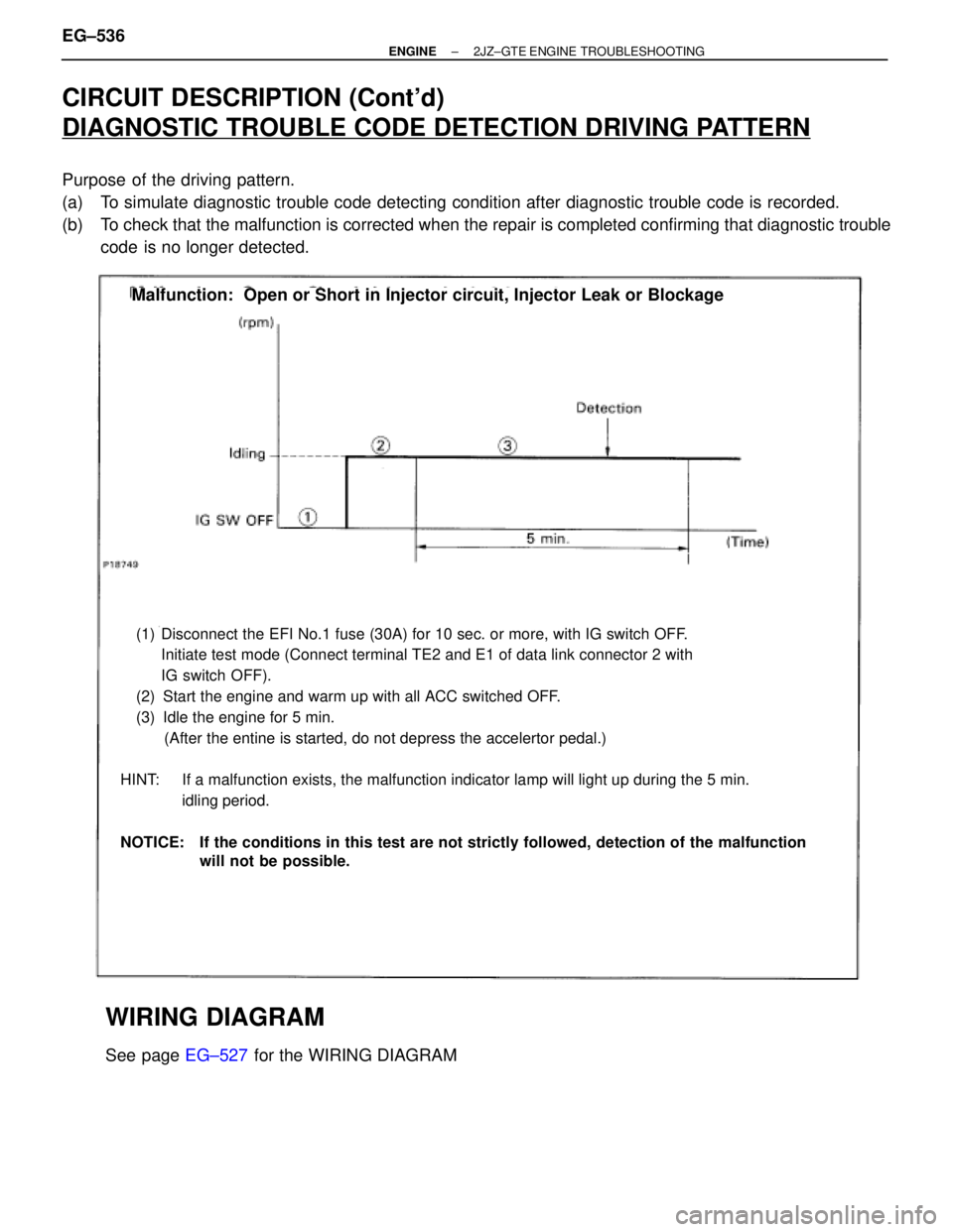
CIRCUIT DESCRIPTION (Cont'd)
DIAGNOSTIC TROUBLE CODE DETECTION DRIVING PATTERN
Purpose of the driving pattern.
(a) To simulate diagnostic trouble code detecting condition after diagnostic trouble code is recorded.
(b) To check that the malfunction is corrected when the repair is completed confirming that diagnostic trouble
code is no longer detected.
(1) Disconnect the EFI No.1 fuse (30A) for 10 sec. or more, with IG switch OFF.
Initiate test mode (Connect terminal TE2 and E1 of data link connector 2 with
IG switch OFF).
(2) Start the engine and warm up with all ACC switched OFF.
(3) Idle the engine for 5 min.
(After the entine is started, do not depress the accelertor pedal.)
HINT: If a malfunction exists, the malfunction indicator lamp will light up during the 5 min.
idling period.
NOTICE: If the conditions in this test are not strictly followed, detection of the malfunction
will not be possible.
Malfunction: Open or Short in Injector circuit, Injector Leak or Blockage
WIRING DIAGRAM
See page EG±527 for the WIRING DIAGRAM EG±536
± ENGINE2JZ±GTE ENGINE TROUBLESHOOTING
Page 115 of 878
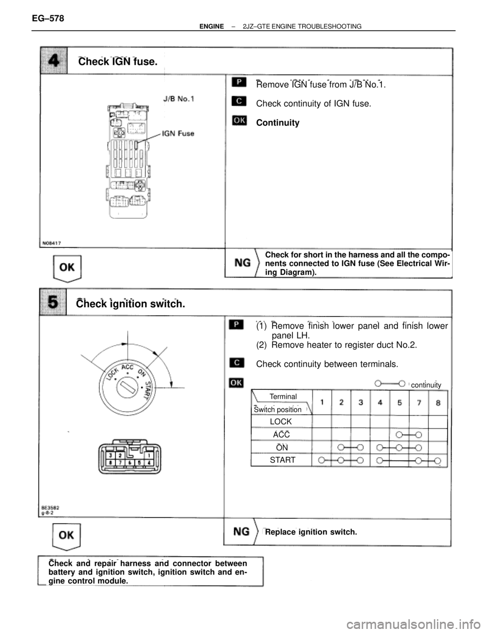
Check for short in the harness and all the compo-
nents connected to IGN fuse (See Electrical Wir-
ing Diagram).
Remove IGN fuse from J/B No.1.
Check continuity of IGN fuse.
Continuity
Check IGN fuse.
Check ignition switch.
(1) Remove finish lower panel and finish lower
panel LH.
(2) Remove heater to register duct No.2.
Check continuity between terminals.
Check and repair harness and connector between
battery and ignition switch, ignition switch and en-
gine control module.
Replace ignition switch.
Terminal
Switch position
LOCK
ACC
ON
START
continuity
EG±578± ENGINE2JZ±GTE ENGINE TROUBLESHOOTING
Page 116 of 878
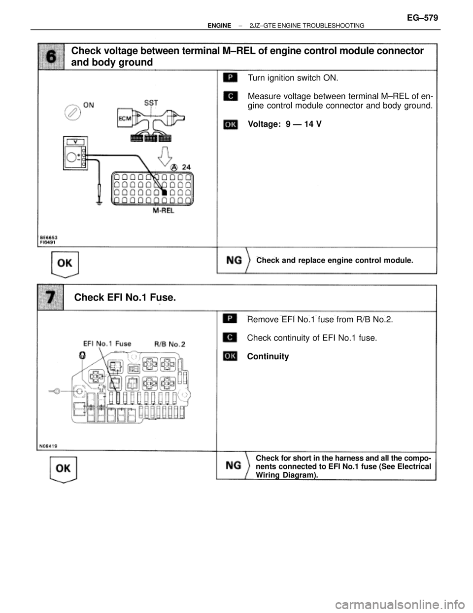
Check for short in the harness and all the compo-
nents connected to EFI No.1 fuse (See Electrical
Wiring Diagram).
Turn ignition switch ON.
Measure voltage between terminal M±REL of en-
gine control module connector and body ground.
Voltage: 9 Ð 14 V
Check voltage between terminal M±REL of engine control module connector
and body ground
Check EFI No.1 Fuse.
Remove EFI No.1 fuse from R/B No.2.
Check continuity of EFI No.1 fuse.
Continuity
Check and replace engine control module.
± ENGINE2JZ±GTE ENGINE TROUBLESHOOTINGEG±579
Page 119 of 878
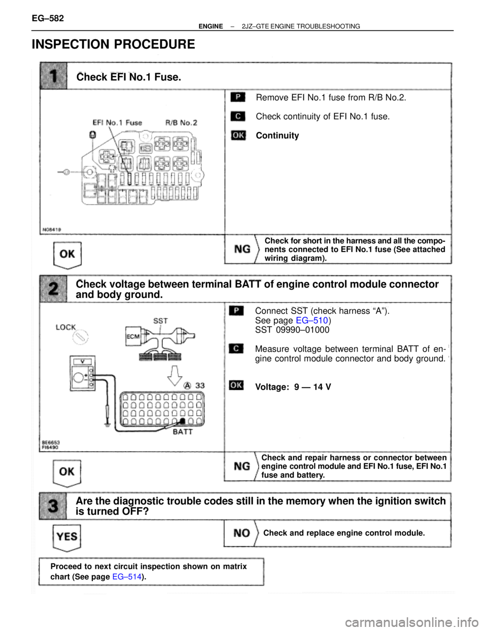
INSPECTION PROCEDURE
(See page EG±510)
Check and repair harness or connector between
engine control module and EFI No.1 fuse, EFI No.1
fuse and battery.
Remove EFI No.1 fuse from R/B No.2.
Check continuity of EFI No.1 fuse.
Continuity
Check EFI No.1 Fuse.
Check voltage between terminal BATT of engine control module connector
and body ground.
Connect SST (check harness ªAº).
See page EG±510)
SST 09990±01000
Measure voltage between terminal BATT of en-
gine control module connector and body ground.
Voltage: 9 Ð 14 V
Check for short in the harness and all the compo-
nents connected to EFI No.1 fuse (See attached
wiring diagram).
Are the diagnostic trouble codes still in the memory when the ignition switch
is turned OFF?
Check and replace engine control module.
Proceed to next circuit inspection shown on matrix
chart (See page EG±514).
EG±582± ENGINE2JZ±GTE ENGINE TROUBLESHOOTING
Page 186 of 878
See page
EG±421
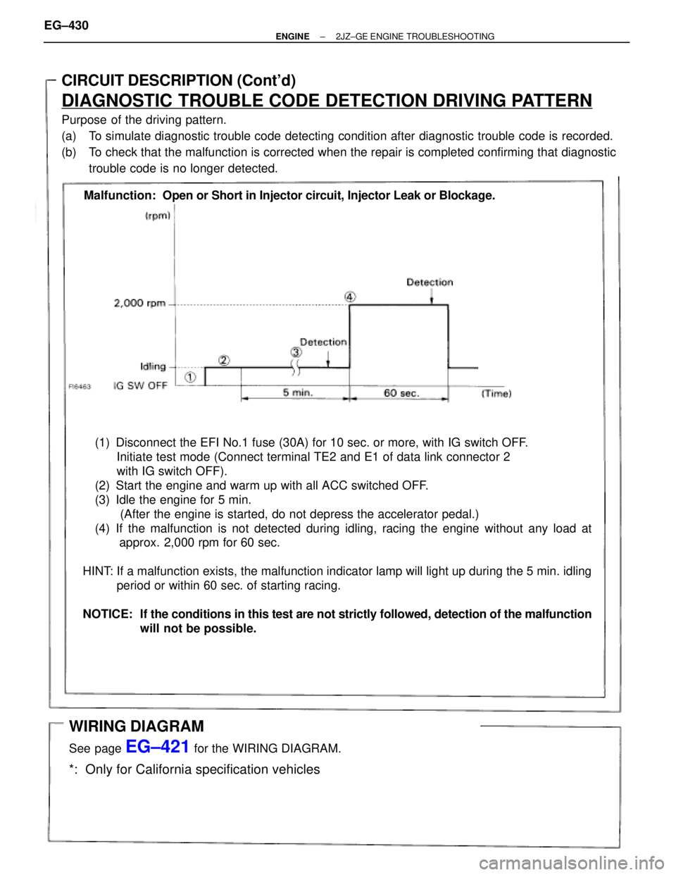
(1) Disconnect the EFI No.1 fuse (30A) for 10 sec. or more, with IG switch OFF.
Initiate test mode (Connect terminal TE2 and E1 of data link connector 2
with IG switch OFF).
(2) Start the engine and warm up with all ACC switched OFF.
(3) Idle the engine for 5 min.
(After the engine is started, do not depress the accelerator pedal.)
(4) If the malfunction is not detected during idling, racing the engine without any load at
approx. 2,000 rpm for 60 sec.
HINT: If a malfunction exists, the malfunction indicator lamp will light up during the 5 min. idling
period or within 60 sec. of starting racing.
NOTICE: If the conditions in this test are not strictly followed, detection of the malfunction
will not be possible.
CIRCUIT DESCRIPTION (Cont'd)
DIAGNOSTIC TROUBLE CODE DETECTION DRIVING PATTERN
Purpose of the driving pattern.
(a) To simulate diagnostic trouble code detecting condition after diagnostic trouble code is recorded.
(b) To check that the malfunction is corrected when the repair is completed confirming that diagnostic
trouble code is no longer detected.
Malfunction: Open or Short in Injector circuit, Injector Leak or Blockage.
WIRING DIAGRAM
See page EG±421 for the WIRING DIAGRAM.
*: Only for California specification vehicles
EG±430± ENGINE2JZ±GE ENGINE TROUBLESHOOTING
Page 223 of 878
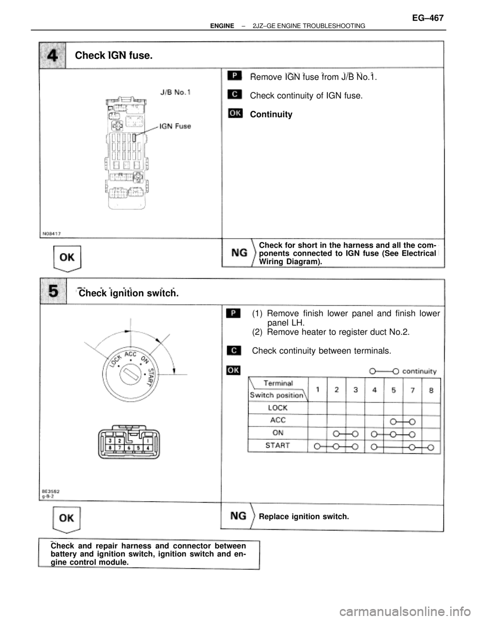
Check IGN fuse.
Remove IGN fuse from J/B No.1.
Check continuity of IGN fuse.
Continuity
Check for short in the harness and all the com-
ponents connected to IGN fuse (See Electrical
Wiring Diagram).
Check ignition switch.
(1) Remove finish lower panel and finish lower
panel LH.
(2) Remove heater to register duct No.2.
Check continuity between terminals.
Replace ignition switch.
Check and repair harness and connector between
battery and ignition switch, ignition switch and en-
gine control module.
± ENGINE2JZ±GE ENGINE TROUBLESHOOTINGEG±467
Page 224 of 878
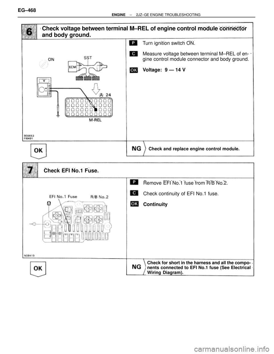
Check voltage between terminal M±REL of engine control module connector
and body ground.
Turn ignition switch ON.
Measure voltage between terminal M±REL of en-
gine control module connector and body ground.
Voltage: 9 Ð 14 V
Check and replace engine control module.
Check EFI No.1 Fuse.
Remove EFI No.1 fuse from R/B No.2.
Check continuity of EFI No.1 fuse.
Continuity
Check for short in the harness and all the compo-
nents connected to EFI No.1 fuse (See Electrical
Wiring Diagram).
EG±468± ENGINE2JZ±GE ENGINE TROUBLESHOOTING
Page 227 of 878
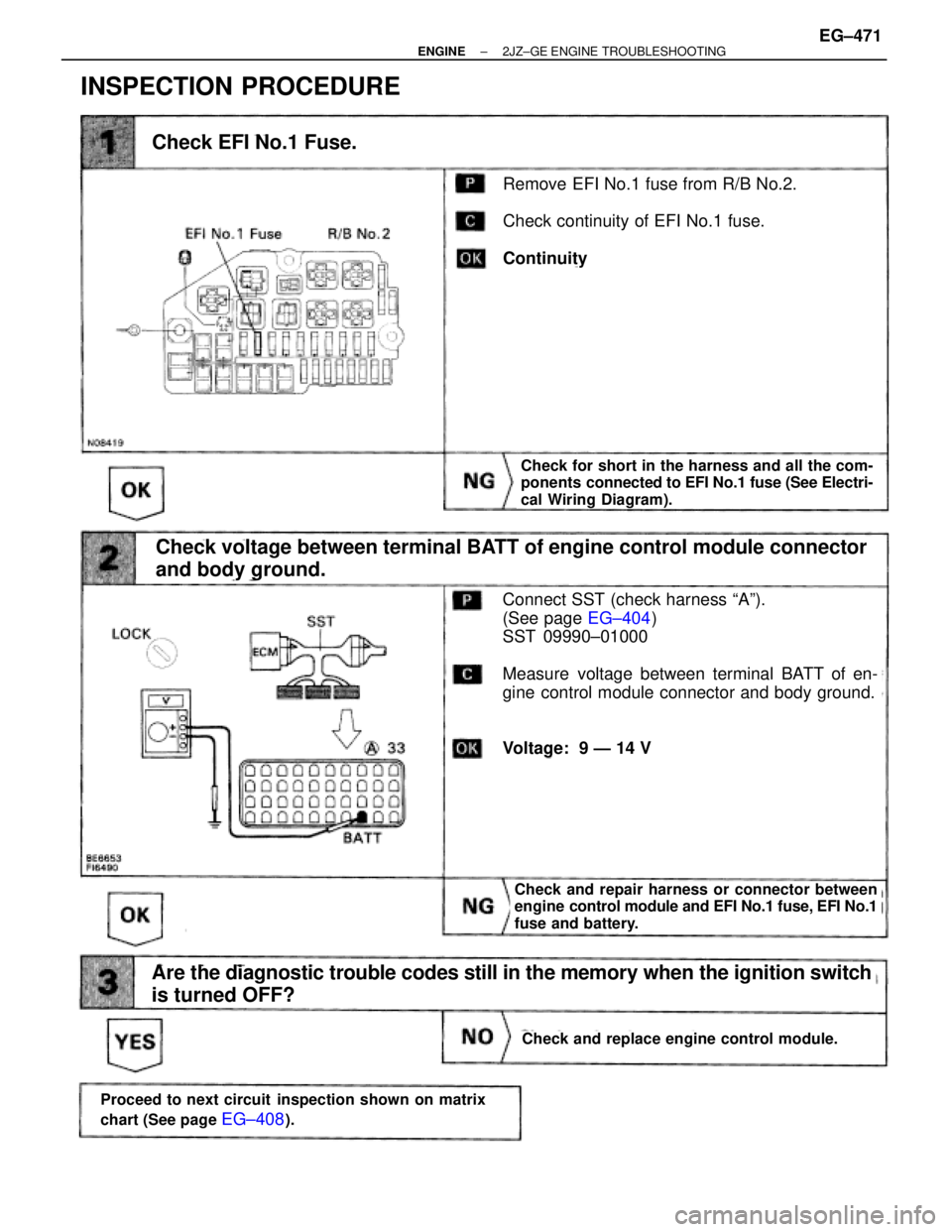
INSPECTION PROCEDURE
Check EFI No.1 Fuse.
Remove EFI No.1 fuse from R/B No.2.
Check continuity of EFI No.1 fuse.
Continuity
Check for short in the harness and all the com-
ponents connected to EFI No.1 fuse (See Electri-
cal Wiring Diagram).
Connect SST (check harness ªAº).
(See page EG±404)
SST 09990±01000
Measure voltage between terminal BATT of en-
gine control module connector and body ground.
Voltage: 9 Ð 14 V
Check and replace engine control module.
Check and repair harness or connector between
engine control module and EFI No.1 fuse, EFI No.1
fuse and battery.
Proceed to next circuit inspection shown on matrix
chart (See page
EG±408).
Check voltage between terminal BATT of engine control module connector
and body ground.
Are the diagnostic trouble codes still in the memory when the ignition switch
is turned OFF?
± ENGINE2JZ±GE ENGINE TROUBLESHOOTINGEG±471
Page 609 of 878
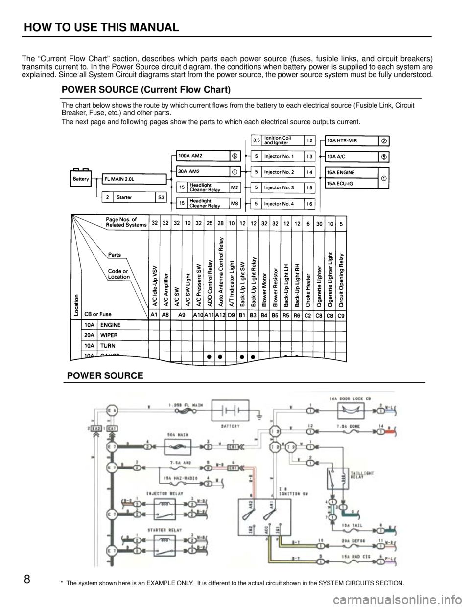
* The system shown here is an EXAMPLE ONLY. It is different to the actual circuit shown in the SYSTEM CIRCUITS SECTION.
POWER SOURCE (Current Flow Chart)
The chart below shows the route by which current flows from the battery to each electrical source (Fusible Link, Circuit
Breaker, Fuse, etc.) and other parts.
The next page and following pages show the parts to which each electrical source outputs current.
POWER SOURCE
8
HOW TO USE THIS MANUAL
The ªCurrent Flow Chartº section, describes which parts each power source (fuses, fusible links, and circuit breakers)
transmits current to. In the Power Source circuit diagram, the conditions when battery power is supplied to each system are
explained. Since all System Circuit diagrams start from the power source, the power source system must be fully understood.