instrument panel TOYOTA SUPRA 1995 Service User Guide
[x] Cancel search | Manufacturer: TOYOTA, Model Year: 1995, Model line: SUPRA, Model: TOYOTA SUPRA 1995Pages: 2543, PDF Size: 53.25 MB
Page 733 of 2543
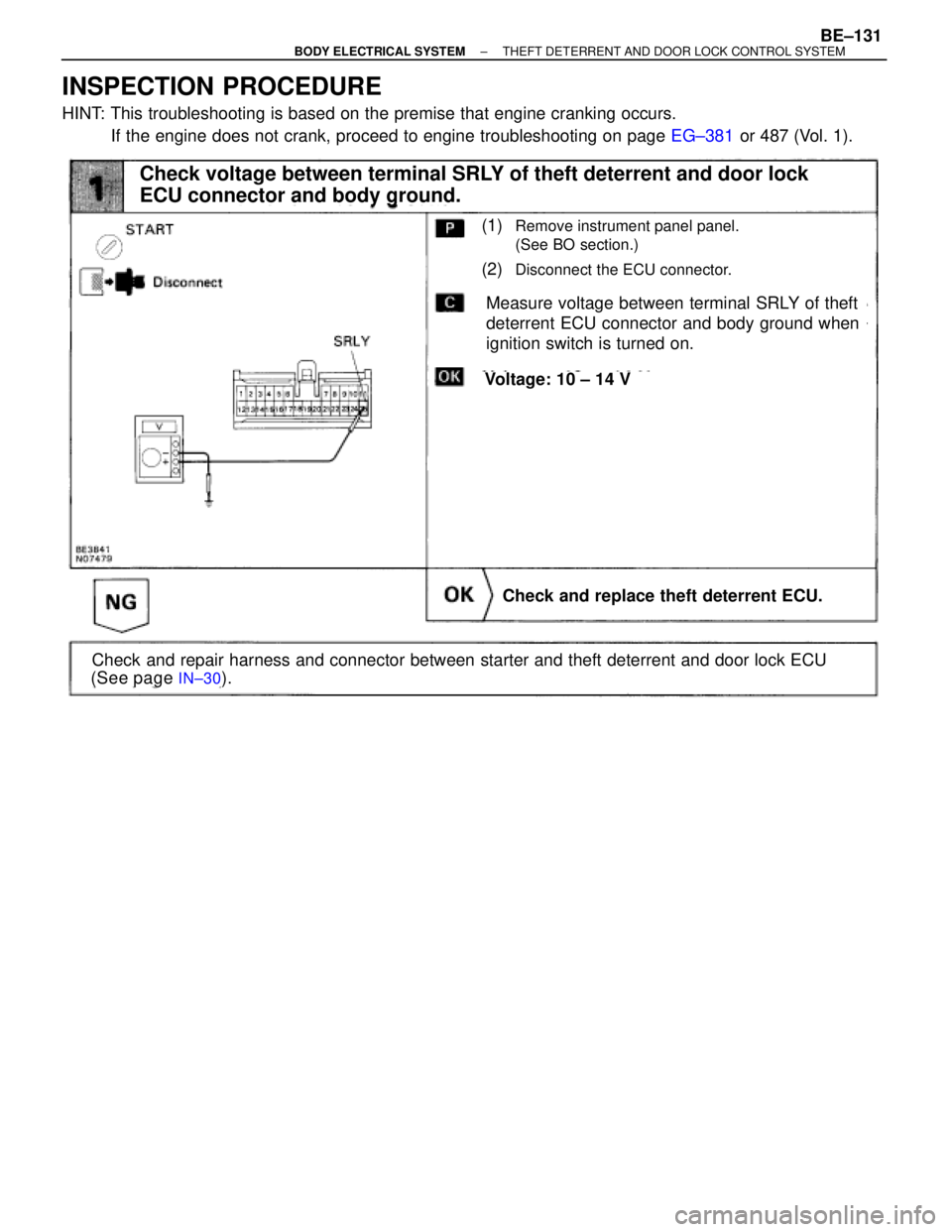
INSPECTION PROCEDURE
HINT: This troubleshooting is based on the premise that engine cranking occurs.
If the engine does not crank, proceed to engine troubleshooting on page EG±381 or 487 (Vol. 1).
(See page IN±30).
(1)Remove instrument panel panel.
(See BO section.)
(2)Disconnect the ECU connector.
Measure voltage between terminal SRLY of theft
deterrent ECU connector and body ground when
ignition switch is turned on.
Voltage: 10 ± 14 V
Check and replace theft deterrent ECU.
Check voltage between terminal SRLY of theft deterrent and door lock
ECU connector and body ground.
Check and repair harness and connector between starter and theft deterrent and door lock ECU
± BODY ELECTRICAL SYSTEMTHEFT DETERRENT AND DOOR LOCK CONTROL SYSTEMBE±131
Page 735 of 2543
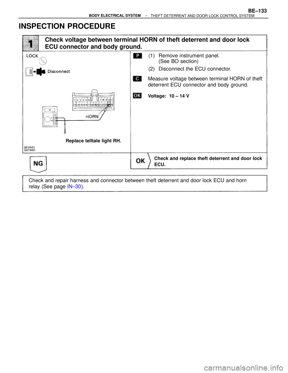
INSPECTION PROCEDURE
(See page IN±30).
Check and repair harness and connector between theft deterrent and door lock ECU and horn
relay (See page IN±30).
(1) Remove instrument panel.
(See BO section)
(2) Disconnect the ECU connector.
Voltage: 10 ± 14 V
Replace telltale light RH.
Check and replace theft deterrent and door lock
ECU.
Check voltage between terminal HORN of theft deterrent and door lock
ECU connector and body ground.
Measure voltage between terminal HORN of theft
deterrent ECU connector and body ground.
± BODY ELECTRICAL SYSTEMBE±133THEFT DETERRENT AND DOOR LOCK CONTROL SYSTEM
Page 739 of 2543
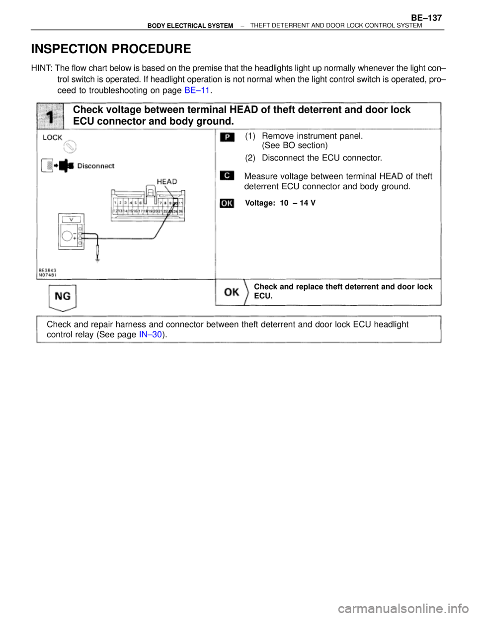
INSPECTION PROCEDURE
HINT: The flow chart below is based on the premise that the headlights light up normally whenever the light con±
trol switch is operated. If headlight operation is not normal when the light control switch is operated, pro±
ceed to troubleshooting on page BE±11.
Check and replace theft deterrent and door lock
ECU.
Measure voltage between terminal HEAD of theft
deterrent ECU connector and body ground.
Voltage: 10 ± 14 V
Check and repair harness and connector between theft deterrent and door lock ECU headlight
control relay (See page IN±30).
Check voltage between terminal HEAD of theft deterrent and door lock
ECU connector and body ground.
(1) Remove instrument panel.
(See BO section)
(2) Disconnect the ECU connector.
± BODY ELECTRICAL SYSTEMBE±137THEFT DETERRENT AND DOOR LOCK CONTROL SYSTEM
Page 741 of 2543
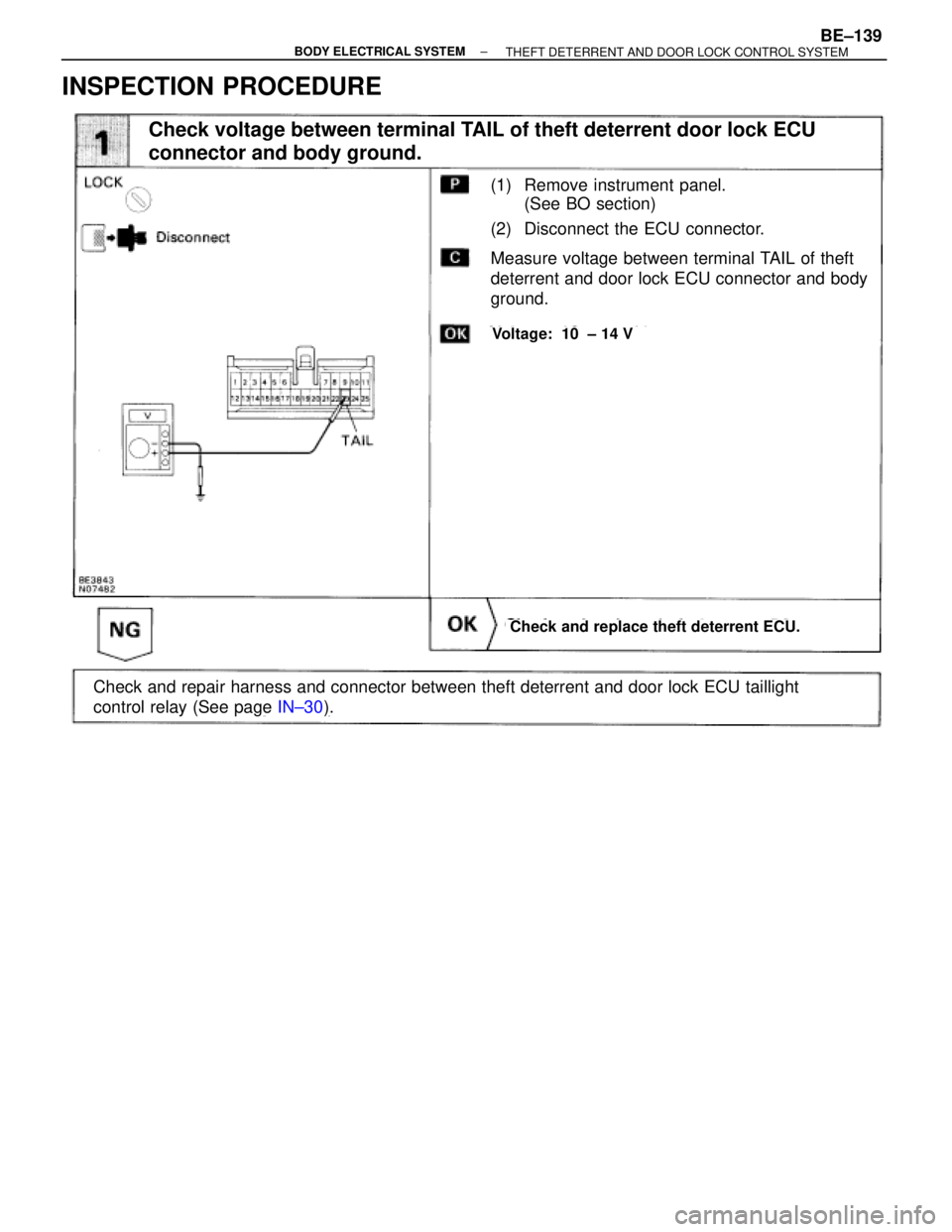
INSPECTION PROCEDURE
(See page IN±30).
(1) Remove instrument panel.
(See BO section)
(2) Disconnect the ECU connector.
Check and replace theft deterrent ECU.
Measure voltage between terminal TAIL of theft
deterrent and door lock ECU connector and body
ground.
Voltage: 10 ± 14 V
Check and repair harness and connector between theft deterrent and door lock ECU taillight
control relay (See page IN±30).
Check voltage between terminal TAIL of theft deterrent door lock ECU
connector and body ground.
± BODY ELECTRICAL SYSTEMBE±139THEFT DETERRENT AND DOOR LOCK CONTROL SYSTEM
Page 743 of 2543
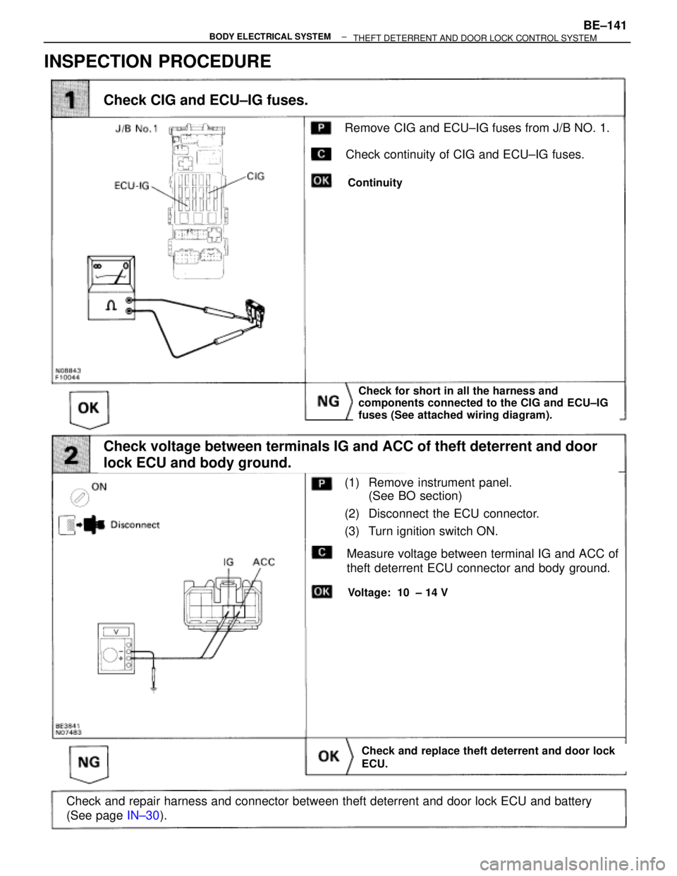
(See page IN±30).
Check for short in all the harness and
components connected to the CIG and ECU±IG
fuses (See attached wiring diagram).
(1) Remove instrument panel.
(See BO section)
(2) Disconnect the ECU connector.
(3) Turn ignition switch ON.
Check and replace theft deterrent and door lock
ECU.
Measure voltage between terminal IG and ACC of
theft deterrent ECU connector and body ground.
Voltage: 10 ± 14 V
Check and repair harness and connector between theft deterrent and door lock ECU and battery
(See page IN±30).
Check voltage between terminals IG and ACC of theft deterrent and door
lock ECU and body ground.
Continuity
Remove CIG and ECU±IG fuses from J/B NO. 1.
Check continuity of CIG and ECU±IG fuses.
Check CIG and ECU±IG fuses.
INSPECTION PROCEDURE
± BODY ELECTRICAL SYSTEMBE±141
THEFT DETERRENT AND DOOR LOCK CONTROL SYSTEM
Page 755 of 2543
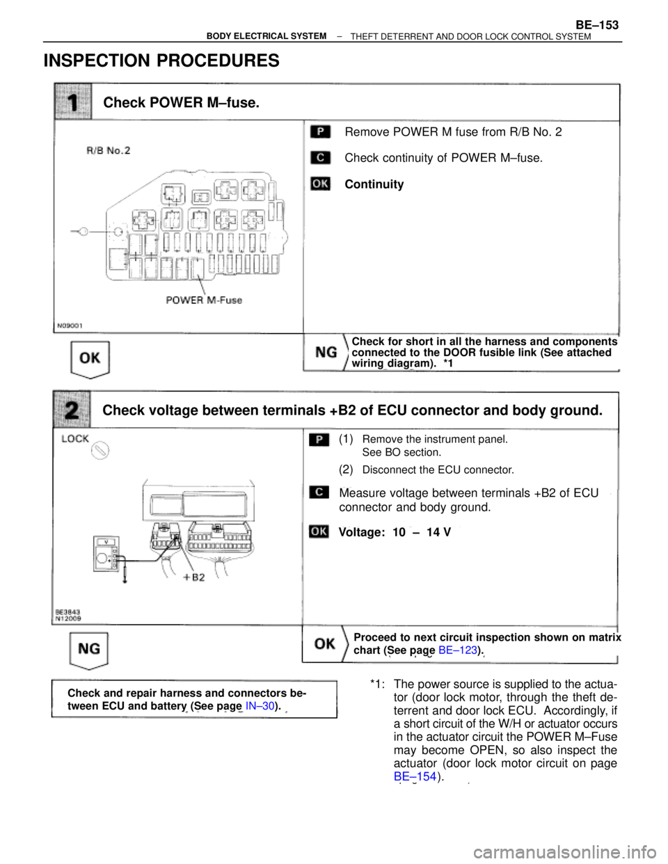
INSPECTION PROCEDURES
(See page BE±123).
page BE±154).
Remove POWER M fuse from R/B No. 2
Check continuity of POWER M±fuse.
Continuity
Check POWER M±fuse.
Check for short in all the harness and components
connected to the DOOR fusible link (See attached
wiring diagram). *1
Proceed to next circuit inspection shown on matrix
chart (See page BE±123).
(1)Remove the instrument panel.
See BO section.
(2)Disconnect the ECU connector.
Measure voltage between terminals +B2 of ECU
connector and body ground.
Check voltage between terminals +B2 of ECU connector and body ground.
Voltage: 10 ± 14 V
*1: The power source is supplied to the actua-
tor (door lock motor, through the theft de-
terrent and door lock ECU. Accordingly, if
a short circuit of the W/H or actuator occurs
in the actuator circuit the POWER M±Fuse
may become OPEN, so also inspect the
actuator (door lock motor circuit on page
BE±154).Check and repair harness and connectors be-
tween ECU and battery (See page IN±30).
± BODY ELECTRICAL SYSTEMBE±153THEFT DETERRENT AND DOOR LOCK CONTROL SYSTEM
Page 792 of 2543
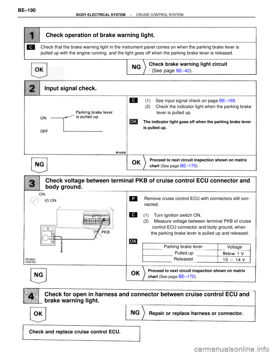
(See page BE±42).
BE±169.
Proceed to next circuit inspection shown on matrix
chart (See page
BE±170).
(1) See input signal check on page BE±169.
(2) Check the indicator light when the parking brake
lever is pulled up.
Check operation of brake warning light.
Check voltage between terminal PKB of cruise control ECU connector and
body ground.
(1) Turn ignition switch ON.
(2) Measure voltage between terminal PKB of cruise
control ECU connector and body ground, when
the parking brake lever is pulled up and released.
Remove cruise control ECU with connectors still con-
nected.
Input signal check.
The indicator light goes off when the parking brake lever
is pulled up.
Check that the brake warning light in the instrument panel comes on when the parking brake lever is
pulled up with the engine running, and the light goes off when the parking brake lever is released.
Check brake warning light circuit
Parking brake lever
Proceed to next circuit inspection shown on matrix
chart (See page
BE±170).
Voltage
Pulled up
Released
Check for open in harness and connector between cruise control ECU and
brake warning light.
Repair or replace harness or connector.
Check and replace cruise control ECU. BE±190
± BODY ELECTRICAL SYSTEMCRUISE CONTROL SYSTEM
Page 837 of 2543
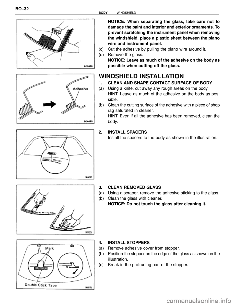
NOTICE: When separating the glass, take care not to
damage the paint and interior and exterior ornaments. To
prevent scratching the instrument panel when removing
the windshield, place a plastic sheet between the piano
wire and instrument panel.
(c) Cut the adhesive by pulling the piano wire around it.
(d) Remove the glass.
NOTICE: Leave as much of the adhesive on the body as
possible when cutting off the glass.
WINDSHIELD INSTALLATION
1. CLEAN AND SHAPE CONTACT SURFACE OF BODY
(a) Using a knife, cut away any rough areas on the body.
HINT: Leave as much of the adhesive on the body as pos-
sible.
(b) Clean the cutting surface of the adhesive with a piece of shop
rag saturated in cleaner.
HINT: Even if all the adhesive has been removed, clean the
body.
2. INSTALL SPACERS
Install the spacers to the body as shown in the illustration.
3. CLEAN REMOVED GLASS
(a) Using a scraper, remove the adhesive sticking to the glass.
(b) Clean the glass with cleaner.
NOTICE: Do not touch the glass after cleaning it.
4. INSTALL STOPPERS
(a) Remove adhesive cover from stopper.
(b) Position the stopper on the edge of the glass as shown on the
illustration.
(c) Break in the protruding part of the stopper. BO±32
± BODYWINDSHIELD
Page 849 of 2543
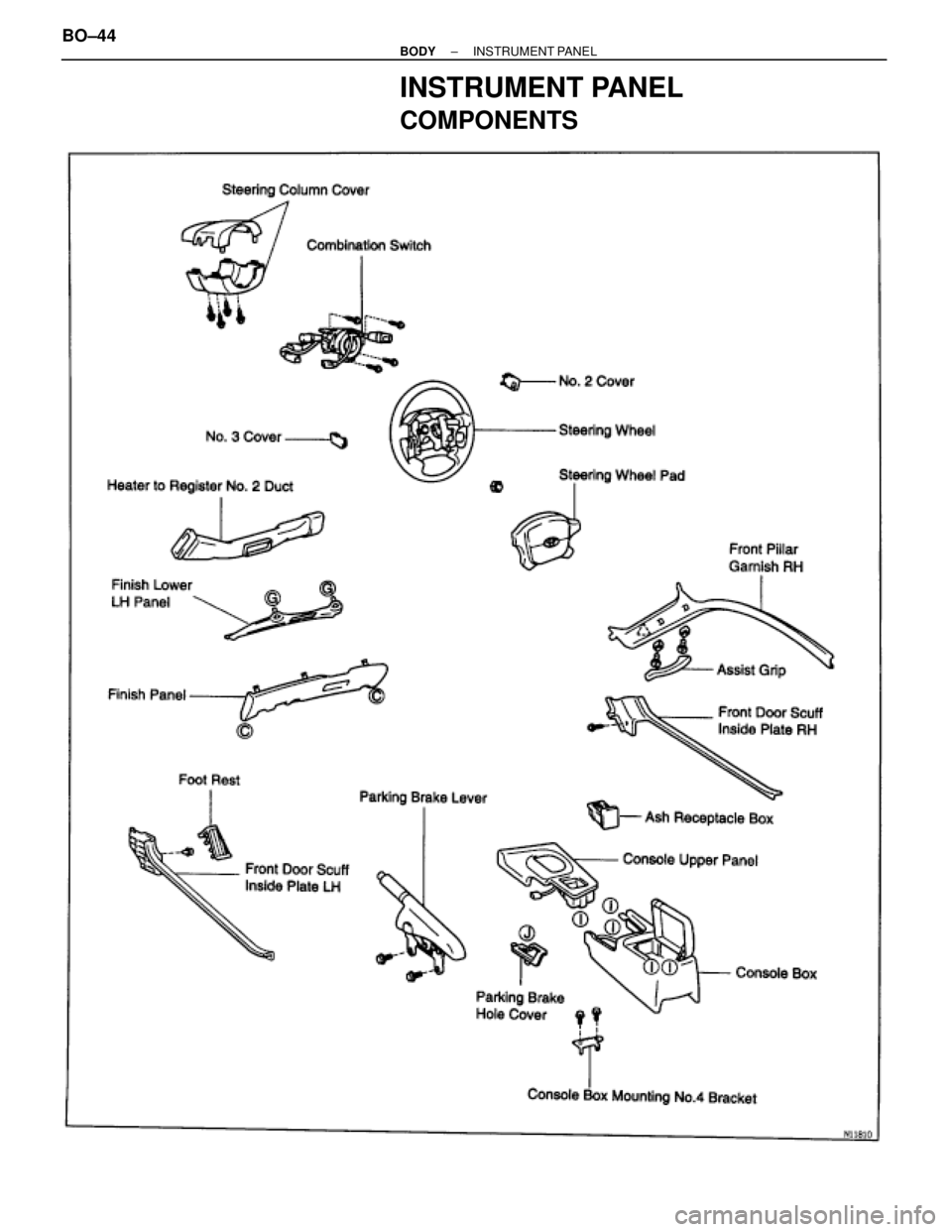
INSTRUMENT PANEL
COMPONENTS
BO±44± BODYINSTRUMENT PANEL
Page 850 of 2543
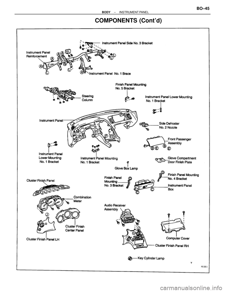
COMPONENTS (Cont'd)
± BODYINSTRUMENT PANELBO±45