battery location TOYOTA SUPRA 1995 Service Repair Manual
[x] Cancel search | Manufacturer: TOYOTA, Model Year: 1995, Model line: SUPRA, Model: TOYOTA SUPRA 1995Pages: 2543, PDF Size: 53.25 MB
Page 1525 of 2543
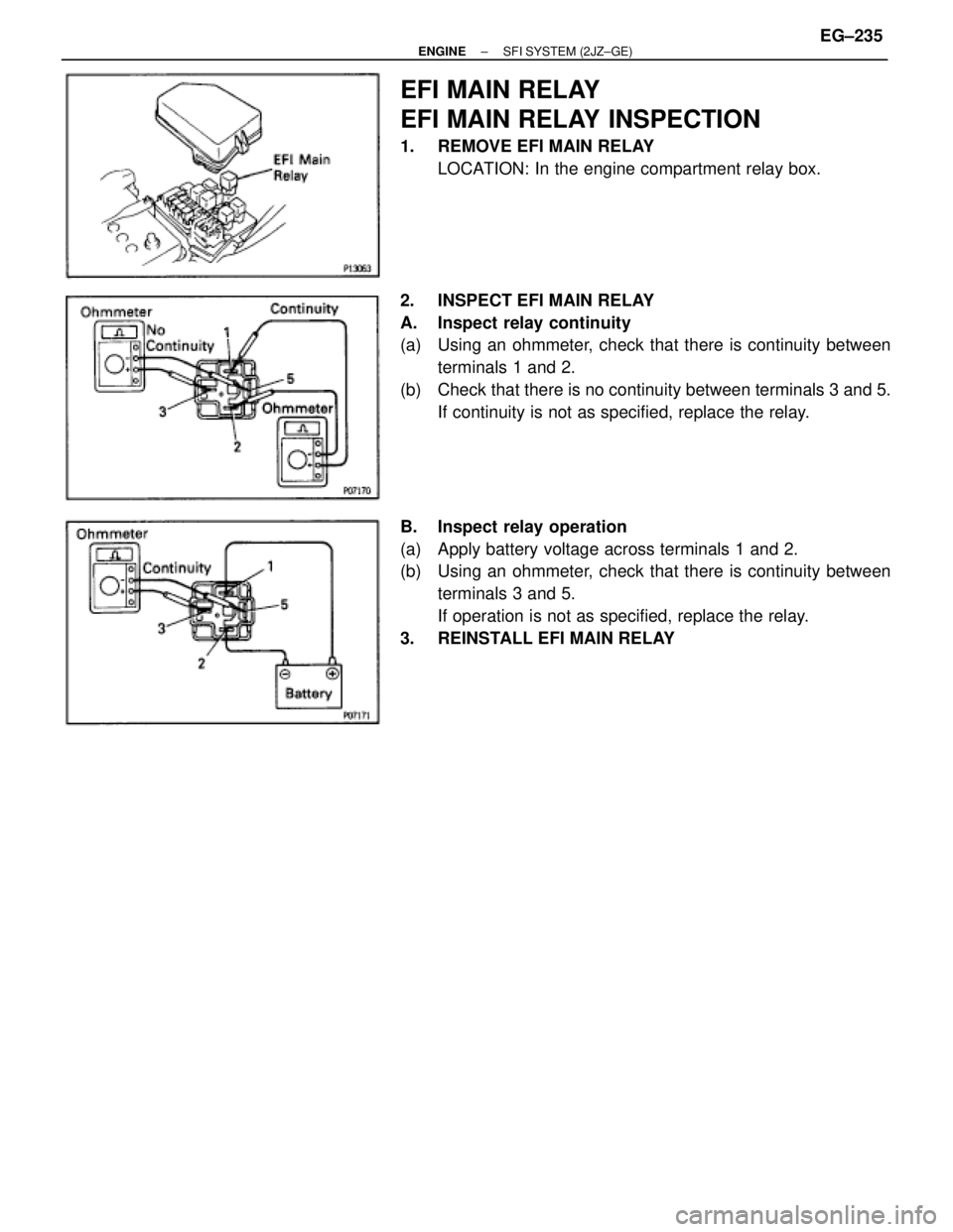
EFI MAIN RELAY
EFI MAIN RELAY INSPECTION
1. REMOVE EFI MAIN RELAY
LOCATION: In the engine compartment relay box.
2. INSPECT EFI MAIN RELAY
A. Inspect relay continuity
(a) Using an ohmmeter, check that there is continuity between
terminals 1 and 2.
(b) Check that there is no continuity between terminals 3 and 5.
If continuity is not as specified, replace the relay.
B. Inspect relay operation
(a) Apply battery voltage across terminals 1 and 2.
(b) Using an ohmmeter, check that there is continuity between
terminals 3 and 5.
If operation is not as specified, replace the relay.
3. REINSTALL EFI MAIN RELAY
± ENGINESFI SYSTEM (2JZ±GE)EG±235
Page 1588 of 2543
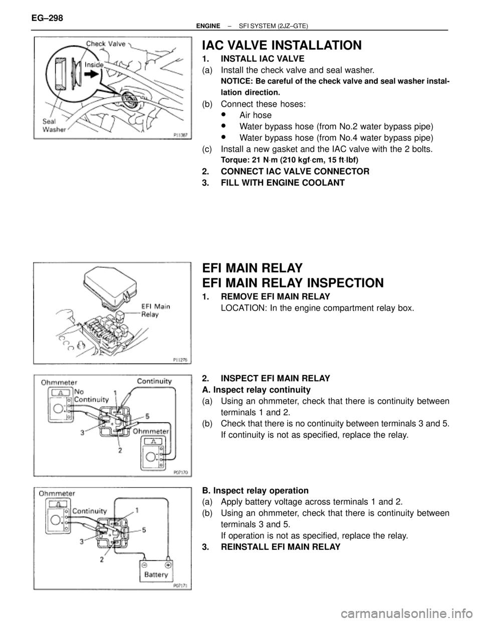
IAC VALVE INSTALLATION
1. INSTALL IAC VALVE
(a) Install the check valve and seal washer.
NOTICE: Be careful of the check valve and seal washer instal-
lation direction.
(b) Connect these hoses:
wAir hose
wWater bypass hose (from No.2 water bypass pipe)
wWater bypass hose (from No.4 water bypass pipe)
(c) Install a new gasket and the IAC valve with the 2 bolts.
Torque: 21 NVm (210 kgfVcm, 15 ftVlbf)
2. CONNECT IAC VALVE CONNECTOR
3. FILL WITH ENGINE COOLANT
EFI MAIN RELAY
EFI MAIN RELAY INSPECTION
1. REMOVE EFI MAIN RELAY
LOCATION: In the engine compartment relay box.
2. INSPECT EFI MAIN RELAY
A. Inspect relay continuity
(a) Using an ohmmeter, check that there is continuity between
terminals 1 and 2.
(b) Check that there is no continuity between terminals 3 and 5.
If continuity is not as specified, replace the relay.
B. Inspect relay operation
(a) Apply battery voltage across terminals 1 and 2.
(b) Using an ohmmeter, check that there is continuity between
terminals 3 and 5.
If operation is not as specified, replace the relay.
3. REINSTALL EFI MAIN RELAY EG±298
± ENGINESFI SYSTEM (2JZ±GTE)
Page 1589 of 2543
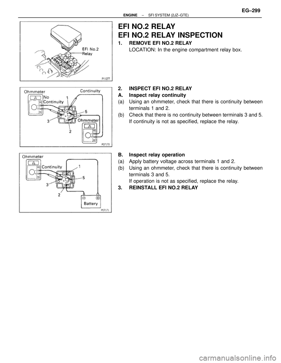
EFI NO.2 RELAY
EFI NO.2 RELAY INSPECTION
1. REMOVE EFI NO.2 RELAY
LOCATION: In the engine compartment relay box.
2. INSPECT EFI NO.2 RELAY
A. Inspect relay continuity
(a) Using an ohmmeter, check that there is continuity between
terminals 1 and 2.
(b) Check that there is no continuity between terminals 3 and 5.
If continuity is not as specified, replace the relay.
B. Inspect relay operation
(a) Apply battery voltage across terminals 1 and 2.
(b) Using an ohmmeter, check that there is continuity between
terminals 3 and 5.
If operation is not as specified, replace the relay.
3. REINSTALL EFI NO.2 RELAY
± ENGINESFI SYSTEM (2JZ±GTE)EG±299
Page 1630 of 2543
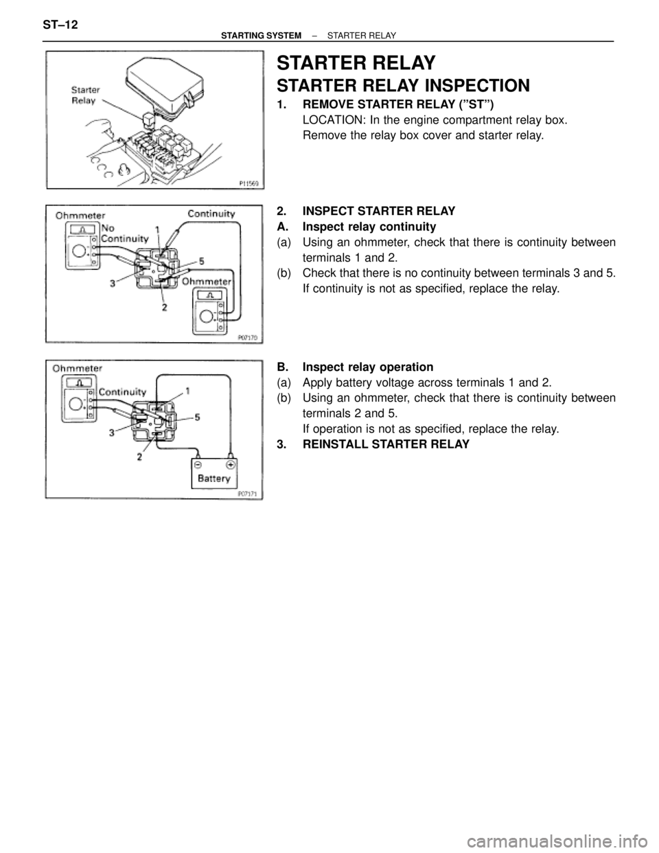
STARTER RELAY
STARTER RELAY INSPECTION
1. REMOVE STARTER RELAY (ºSTº)
LOCATION: In the engine compartment relay box.
Remove the relay box cover and starter relay.
2. INSPECT STARTER RELAY
A. Inspect relay continuity
(a) Using an ohmmeter, check that there is continuity between
terminals 1 and 2.
(b) Check that there is no continuity between terminals 3 and 5.
If continuity is not as specified, replace the relay.
B. Inspect relay operation
(a) Apply battery voltage across terminals 1 and 2.
(b) Using an ohmmeter, check that there is continuity between
terminals 2 and 5.
If operation is not as specified, replace the relay.
3. REINSTALL STARTER RELAY ST±12
± STARTING SYSTEMSTARTER RELAY
Page 1908 of 2543
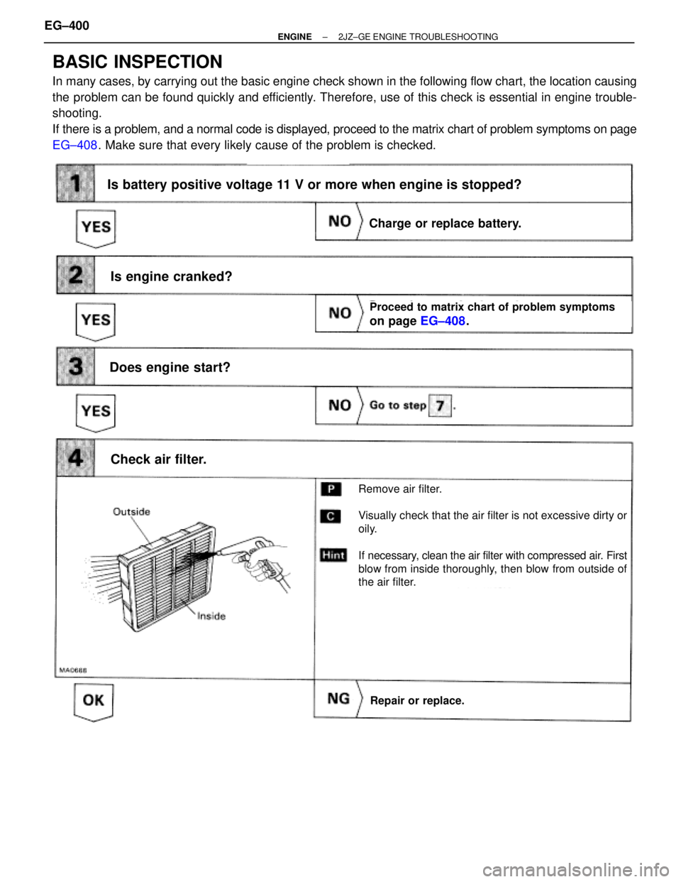
BASIC INSPECTION
In many cases, by carrying out the basic engine check shown in the following flow chart, the location causing
the problem can be found quickly and efficiently. Therefore, use of this check is essential in engine trouble-
shooting.
If there is a problem, and a normal code is displayed, proceed to the matrix chart of problem symptoms on page
EG±408. Make sure that every likely cause of the problem is checked.
EG±408.
Is battery positive voltage 11 V or more when engine is stopped?
Is engine cranked?
Does engine start?
Check air filter.
Charge or replace battery.
Proceed to matrix chart of problem symptoms
on page EG±408.
Repair or replace.
Remove air filter.
Visually check that the air filter is not excessive dirty or
oily.
If necessary, clean the air filter with compressed air. First
blow from inside thoroughly, then blow from outside of
the air filter.
EG±400± ENGINE2JZ±GE ENGINE TROUBLESHOOTING
Page 2013 of 2543
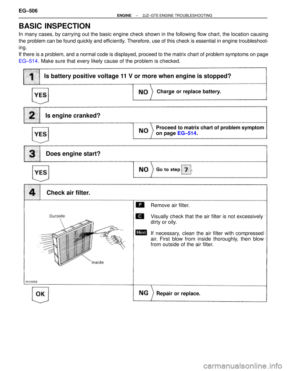
BASIC INSPECTION
In many cases, by carrying out the basic engine check shown in the following flow chart, the location causing
the problem can be found quickly and efficiently. Therefore, use of this check is essential in engine troubleshoot-
ing.
If there is a problem, and a normal code is displayed, proceed to the matrix chart of problem symptoms on page
EG±514. Make sure that every likely cause of the problem is checked.
Is battery positive voltage 11 V or more when engine is stopped?
Is engine cranked?
Does engine start?
Check air filter.
Charge or replace battery.
Proceed to matrix chart of problem symptom
on page EG±514.
Repair or replace.
Remove air filter.
Visually check that the air filter is not excessively
dirty or oily.
If necessary, clean the air filter with compressed
air. First blow from inside thoroughly, then blow
from outside of the air filter.
Charge or replace battery.
Is battery positive voltage 11 V or more when engine is stopped?
EG±506± ENGINE2JZ±GTE ENGINE TROUBLESHOOTING