checking oil TOYOTA SUPRA 1995 Service Repair Manual
[x] Cancel search | Manufacturer: TOYOTA, Model Year: 1995, Model line: SUPRA, Model: TOYOTA SUPRA 1995Pages: 2543, PDF Size: 53.25 MB
Page 1101 of 2543

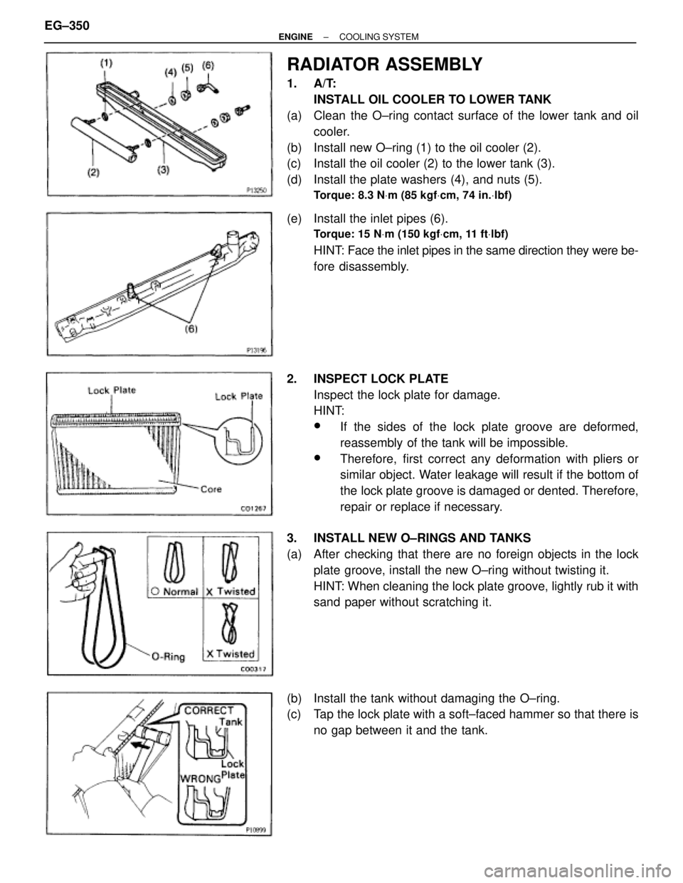
RADIATOR ASSEMBLY
1. A/T:
INSTALL OIL COOLER TO LOWER TANK
(a) Clean the O±ring contact surface of the lower tank and oil
cooler.
(b) Install new O±ring (1) to the oil cooler (2).
(c) Install the oil cooler (2) to the lower tank (3).
(d) Install the plate washers (4), and nuts (5).
Torque: 8.3 NVm (85 kgfVcm, 74 in.Vlbf)
(e) Install the inlet pipes (6).
Torque: 15 NVm (150 kgfVcm, 11 ftVlbf)
HINT: Face the inlet pipes in the same direction they were be-
fore disassembly.
2. INSPECT LOCK PLATE
Inspect the lock plate for damage.
HINT:
wIf the sides of the lock plate groove are deformed,
reassembly of the tank will be impossible.
wTherefore, first correct any deformation with pliers or
similar object. Water leakage will result if the bottom of
the lock plate groove is damaged or dented. Therefore,
repair or replace if necessary.
3. INSTALL NEW O±RINGS AND TANKS
(a) After checking that there are no foreign objects in the lock
plate groove, install the new O±ring without twisting it.
HINT: When cleaning the lock plate groove, lightly rub it with
sand paper without scratching it.
(b) Install the tank without damaging the O±ring.
(c) Tap the lock plate with a soft±faced hammer so that there is
no gap between it and the tank. EG±350
± ENGINECOOLING SYSTEM
Page 1250 of 2543

There are some maintenance and inspection
items which are considered to be the owner's re-
sponsibility. They can be performed by the owner
or be can have them done at a service shop.
These items include those which should be
checked on a daily basis, those which, in most
cases, do not require (special) tools and those
which are considered to be reasonable for the
owner to perform. Items and procedures for gen-
eral maintenance are as follows:
OUTSIDE VEHICLE
1. TIRES
(a) Check the pressure with a gauge. Adjust if
necessary.
(b) Check for cuts, damage, uneven or excessive
wear.
2. WHEEL NUTS
When checking the tires, check the nuts for
looseness or for missing nuts. If necessary,
tighten them.
3. WINDSHIELD WIPER BLADES
Check for wear or cracks whenever they do not
wipe clean. Replace if necessary.
4. FLUID LEAKS
(a) Check underneath for leaking fuel, oil, water or
other fluid.
(b) If you smell gasoline fumes or notice any leak,
have the cause found and corrected.
5. DOORS AND ENGINE HOOD
(a) Check that all doors including the trunk lid
operate smoothly, and that all latches lock
securely.
(b) Check that the engine hood secondary latch
secures the hood from opening when the
primary latch is released.
INSIDE VEHICLE
6. LIGHTS
(a) C h e c k t h a t t h e headlights, stop lights,
tail±lights, turn signal lights, and other lights
are all working.
(b) Check the headlight aiming.7. WARNING LIGHT AND BUZZERS
Check that all warning lights and buzzers
function properly.
8. HORN
Check that it is working.
9. WINDSHIELD GLASS
Check for scratches, pits or abrasions.
10. WINDSHIELD WIPER AND WASHER
(a) Check operation of the wipers and washer.
(b) Check that the wipers do not streak.
11. WINDSHIELD DEFROSTER
Check that the air comes out from the defrost-
er outlet when operating the heater air condi-
tioner at defroster mode.
12. REAR VIEW MIRROR
Check that it is mounted securely.
13. SUN VISORS
Check that they move freely and are
mounted securely.
14. STEERING WHEEL
Check that it has the specified freeplay. Be
alert for changes in steering condition, such
as excessive steering effort, excessive free-
play or strange noise.
15. SEATS
(a) Check that all front seat controls such as seat
adjusters, seatback recliner, etc. operate
smoothly.
(b) Check that all latches lock securely in any
position.
(c) Check that the locks hold securely in any
latched position.
(d) Check that the head restraints move up and
down smoothly and that the locks hold
securely in any latched position.
(e) For folding±down rear seat backs, check that
the latches lock securely.
16. SEAT BELTS
(a) Check that the seat belt system such as
buckles, retractors and anchors operate
properly and smoothly.
(b) Check that the belt webbing is not cut, frayed,
worn or damaged.
17. ACCELERATOR PEDAL
Check the pedal for smooth operation and
uneven pedal effort or catching.
GENERAL MAINTENANCE
± MAINTENANCEGENERAL MAINTENANCEMA±17
Page 1251 of 2543

18. BRAKE PEDAL
(a) Check that pedal for smooth operation.
(b) Check that the pedal has the proper reserve
distance and freeplay.
(c) Check the brake booster function.
19. BRAKES
At a safe place, check that the brakes do not
pull to one side when applied.
20. PARKING BRAKE
(a) Check that the pedal has the proper travel.
(b) On a safe incline, check that the vehicle is
held securely with only the parking brake
applied.
21. AUTOMATIC TRANSMISSION PARK
MECHANISM
(a) Check the lock release button of the selector
lever for proper and smooth operation.
(b) On a safe incline, check that the vehicle is
held securely with the selector lever in the ºPº
position and all brakes released.
UNDER HOOD
22. WINDSHIELD WASHER FLUID
Check that there is sufficient fluid in the tank.
23. ENGINE COOLANT LEVEL
Check that the coolant level is between the
LEVEL lines on the see±through reservoir at
normal temperature (20°C (68°F)).
24. RADIATOR AND HOSES
(a) Check that the front of the radiator is clean
and not blocked with leaves, dirt or bugs.
(b) Check the hoses for cracks, kinks, rot or
loose connections.
25. BATTERY ELECTROLYTE LEVEL
Check the indicator.
When the indicator color is blue, the condition
is satisfactory. A red color indicates that dis-
tilled water must be added, and white indi-
cates that charging is necessary.
26. BRAKE FLUID LEVEL
Check that the brake fluid level is near the up-
per level line on the see±through reservoir.27. ENGINE DRIVE BELT
Check drive belt for fraying, cracks, wear or
oil contamination.
28. ENGINE OIL LEVEL
Check that level on the dipstick with the en-
gine turned off.
29. POWER STEERING FLUID LEVEL
Check the level on the dipstick.
The level should be in the ºHOTº or ºCOLDº
range depending on the fluid temperature.
30. A U TO M AT I C TRANSMISSION FLUID
LEVEL
(a) Park the vehicle on a level surface.
(b) With the engine idling and the parking and
foot brake applied, shift the selector into all
positions from ºPº to ºLº, and then shift into ºPº
position.
(c) Turn and pull out the dipstick and wipe off the
fluid with a clean rag.
Re±insert the dipstick fully and check that the
fluid level is in the ºHOTº range.
(d) Perform this check with the fluid at normal
driving temperature (70±80°C (158±176°F)).
If the level is at the low side, add fluid.
NOTICE: Do not overfill.
HINT: Wait about 30 minutes before checking
the fluid level after extended driving at high
speeds in hot weather, driving in heavy traffic
or with a trailer.
31. EXHAUST SYSTEM
Visually inspect for cracks, holes or loose
supports.
If any change in the sound of the exhaust or
smell of the exhaust fumes is noticed, have
the cause located and correted. MA±18
± MAINTENANCEGENERAL MAINTENANCE
Page 1346 of 2543

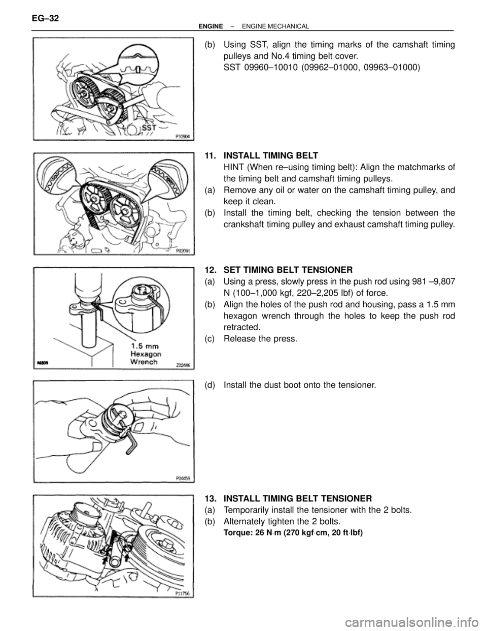
(b) Using SST, align the timing marks of the camshaft timing
pulleys and No.4 timing belt cover.
SST 09960±10010 (09962±01000, 09963±01000)
11. INSTALL TIMING BELT
HINT (When re±using timing belt): Align the matchmarks of
the timing belt and camshaft timing pulleys.
(a) Remove any oil or water on the camshaft timing pulley, and
keep it clean.
(b) Install the timing belt, checking the tension between the
crankshaft timing pulley and exhaust camshaft timing pulley.
12. SET TIMING BELT TENSIONER
(a) Using a press, slowly press in the push rod using 981 ±9,807
N (100±1,000 kgf, 220±2,205 lbf) of force.
(b) Align the holes of the push rod and housing, pass a 1.5 mm
hexagon wrench through the holes to keep the push rod
retracted.
(c) Release the press.
(d) Install the dust boot onto the tensioner.
13. INSTALL TIMING BELT TENSIONER
(a) Temporarily install the tensioner with the 2 bolts.
(b) Alternately tighten the 2 bolts.
Torque: 26 NVm (270 kgfVcm, 20 ftVlbf)
EG±32± ENGINEENGINE MECHANICAL