lights TOYOTA SUPRA 1995 Service Repair Manual
[x] Cancel search | Manufacturer: TOYOTA, Model Year: 1995, Model line: SUPRA, Model: TOYOTA SUPRA 1995Pages: 2543, PDF Size: 53.25 MB
Page 67 of 2543
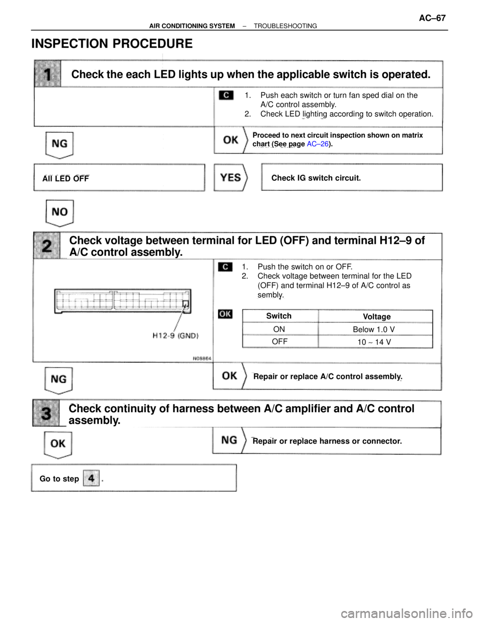
INSPECTION PROCEDURE
Check the each LED lights up when the applicable switch is operated.
Proceed to next circuit inspection shown on matrix
chart (See page AC┬▒26).
Check voltage between terminal for LED (OFF) and terminal H12┬▒9 of
A/C control assembly.
Check continuity of harness between A/C amplifier and A/C control
assembly.
Go to step
Repair or replace harness or connector.
Repair or replace A/C control assembly.
Switch
ON
OFF
Below 1.0 V
10 ~ 14 V
Voltage
All LED OFFCheck IG switch circuit.
1. Push the switch on or OFF.
2. Check voltage between terminal for the LED
(OFF) and terminal H12┬▒9 of A/C control as
sembly.
1. Push each switch or turn fan sped dial on the
A/C control assembly.
2. Check LED lighting according to switch operation.
┬▒ AIR CONDITIONING SYSTEMTROUBLESHOOTINGAC┬▒67
Page 420 of 2543
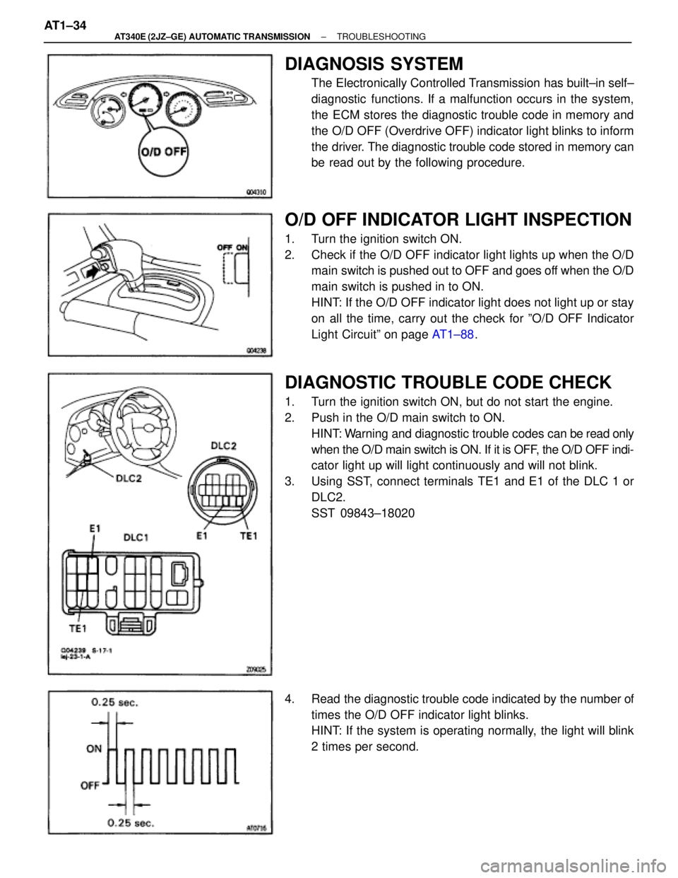
DIAGNOSIS SYSTEM
The Electronically Controlled Transmission has built┬▒in self┬▒
diagnostic functions. If a malfunction occurs in the system,
the ECM stores the diagnostic trouble code in memory and
the O/D OFF (Overdrive OFF) indicator light blinks to inform
the driver. The diagnostic trouble code stored in memory can
be read out by the following procedure.
O/D OFF INDICATOR LIGHT INSPECTION
1. Turn the ignition switch ON.
2. Check if the O/D OFF indicator light lights up when the O/D
main switch is pushed out to OFF and goes off when the O/D
main switch is pushed in to ON.
HINT: If the O/D OFF indicator light does not light up or stay
on all the time, carry out the check for ┬║O/D OFF Indicator
Light Circuit┬║ on page AT1┬▒88.
DIAGNOSTIC TROUBLE CODE CHECK
1. Turn the ignition switch ON, but do not start the engine.
2. Push in the O/D main switch to ON.
HINT: Warning and diagnostic trouble codes can be read only
when the O/D main switch is ON. If it is OFF, the O/D OFF indi-
cator light up will light continuously and will not blink.
3. Using SST, connect terminals TE1 and E1 of the DLC 1 or
DLC2.
SST 09843┬▒18020
4. Read the diagnostic trouble code indicated by the number of
times the O/D OFF indicator light blinks.
HINT: If the system is operating normally, the light will blink
2 times per second. AT1┬▒34
┬▒ AT340E (2JZ┬▒GE) AUTOMATIC TRANSMISSIONTROUBLESHOOTING
Page 423 of 2543
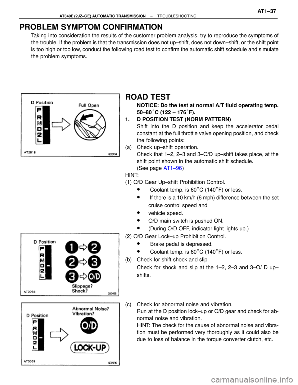
PROBLEM SYMPTOM CONFIRMATION
Taking into consideration the results of the customer problem analysis, try to reproduce the symptoms of
the trouble. If the problem is that the transmission does not up┬▒shift, does not down┬▒shift, or the shift point
is too high or too low, conduct the following road test to confirm the automatic shift schedule and simulate
the problem symptoms.
ROAD TEST
NOTICE: Do the test at normal A/T fluid operating temp.
50┬▒80┬░C (122 ┬▒ 176┬░F).
1. D POSITION TEST (NORM PATTERN)
Shift into the D position and keep the accelerator pedal
constant at the full throttle valve opening position, and check
the following points:
(a) Check up┬▒shift operation.
Check that 1┬▒2, 2┬▒3 and 3┬▒O/D up┬▒shift takes place, at the
shift point shown in the automatic shift schedule.
(See page AT1┬▒96)
HINT:
(1) O/D Gear Up┬▒shift Prohibition Control.
w Coolant temp. is 60┬░C (140┬░F) or less.
w If there is a 10 km/h (6 mph) difference between the set
cruise control speed and
wvehicle speed.
wO/D main switch is pushed ON.
w(During O/D OFF, indicator light lights up.)
(2) O/D Gear Lock┬▒up Prohibition Control.
w Brake pedal is depressed.
w Coolant temp. is 60┬░C (140┬░F) or less.
(b) Check for shift shock and slip.
Check for shock and slip at the 1┬▒2, 2┬▒3 and 3┬▒O/ D up┬▒
shifts.
(c) Check for abnormal noise and vibration.
Run at the D position lock┬▒up or O/D gear and check for ab-
normal noise and vibration.
HINT: The check for the cause of abnormal noise and vibra-
tion must be performed very thoroughly as it could also be
due to loss of balance in the torque converter clutch, etc.
┬▒ AT340E (2JZ┬▒GE) AUTOMATIC TRANSMISSIONTROUBLESHOOTINGAT1┬▒37
Page 469 of 2543
See
Stop Light Switch Circuit
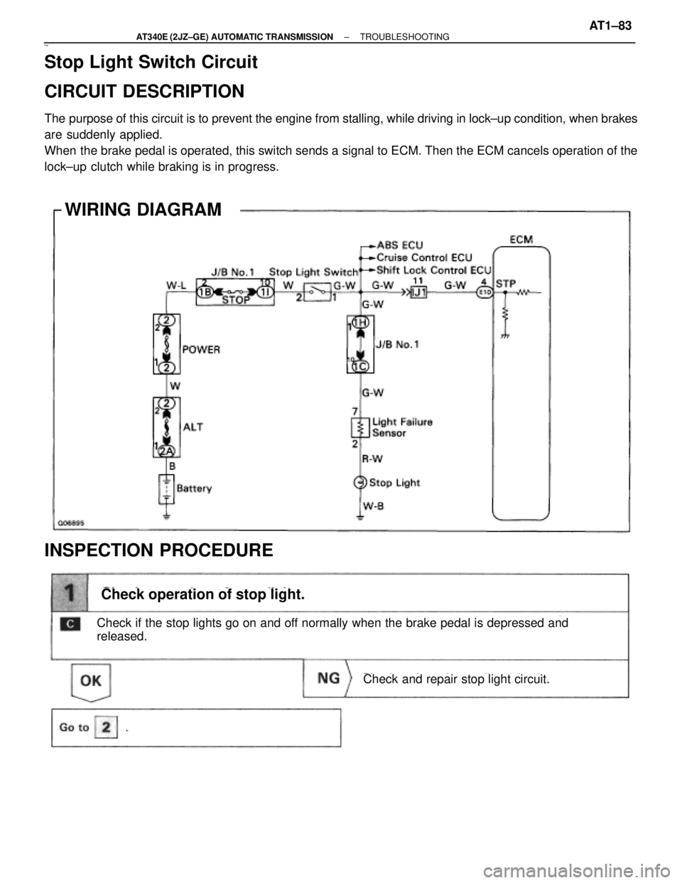
CIRCUIT DESCRIPTION
The purpose of this circuit is to prevent the engine from stalling, while driving in lock┬▒up condition, when brakes
are suddenly applied.
When the brake pedal is operated, this switch sends a signal to ECM. Then the ECM cancels operation of the
lock┬▒up clutch while braking is in progress.
WIRING DIAGRAM
INSPECTION PROCEDURE
Check operation of stop light.
Check and repair stop light circuit.
Check if the stop lights go on and off normally when the brake pedal is depressed and
released.
┬▒ AT340E (2JZ┬▒GE) AUTOMATIC TRANSMISSIONTROUBLESHOOTINGAT1┬▒83
Page 474 of 2543
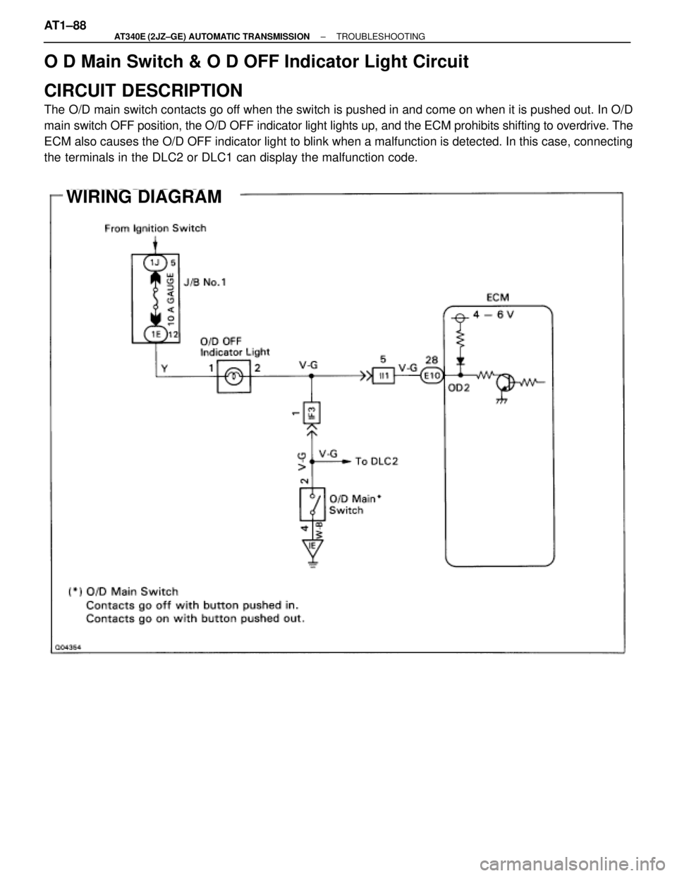
O D Main Switch & O D OFF Indicator Light Circuit
CIRCUIT DESCRIPTION
The O/D main switch contacts go off when the switch is pushed in and come on when it is pushed out. In O/D
main switch OFF position, the O/D OFF indicator light lights up, and the ECM prohibits shifting to overdrive. The
ECM also causes the O/D OFF indicator light to blink when a malfunction is detected. In this case, connecting
the terminals in the DLC2 or DLC1 can display the malfunction code.
WIRING DIAGRAM
AT1┬▒88┬▒ AT340E (2JZ┬▒GE) AUTOMATIC TRANSMISSIONTROUBLESHOOTING
Page 475 of 2543
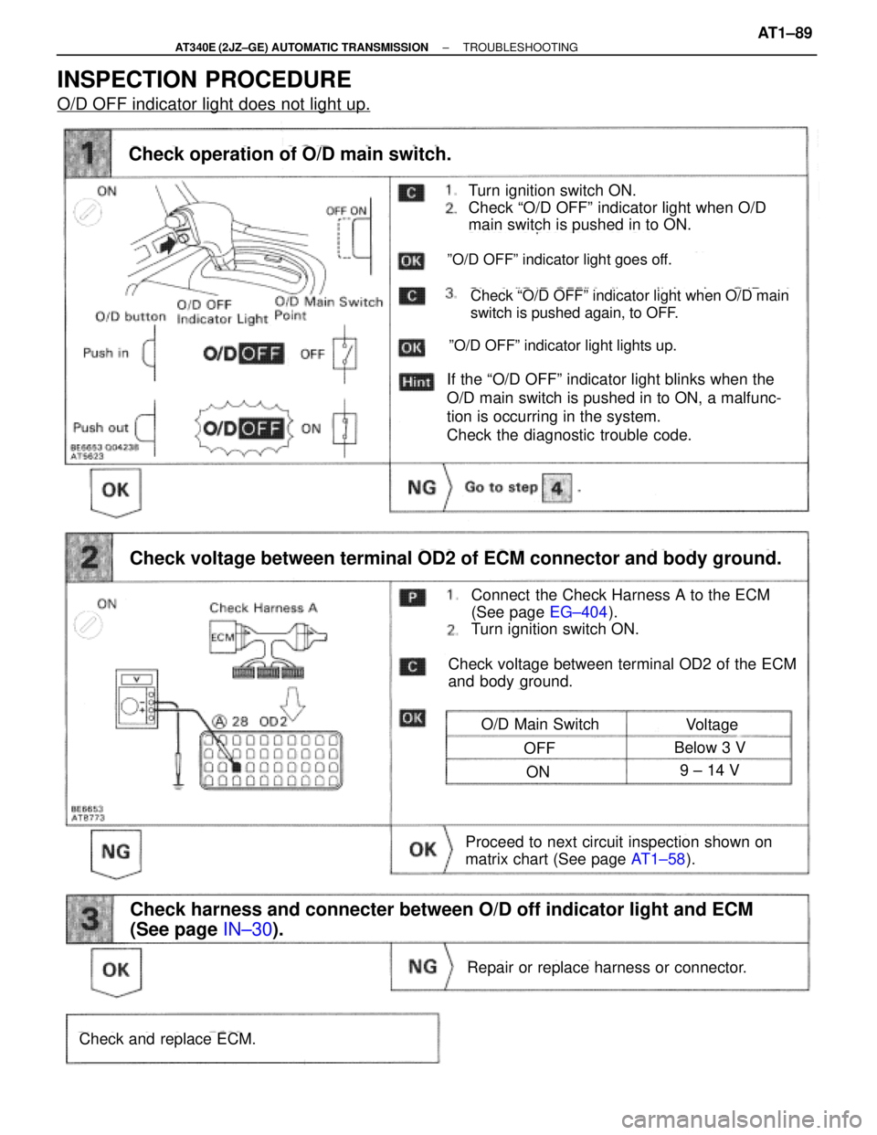
INSPECTION PROCEDURE
O/D OFF indicator light does not light up.
Turn ignition switch ON.
Check ªO/D OFFº indicator light when O/D
main switch is pushed in to ON.
Check operation of O/D main switch.
Connect the Check Harness A to the ECM
(See page EG┬▒404).
Turn ignition switch ON.
┬║O/D OFF┬║ indicator light goes off.
If the ªO/D OFFº indicator light blinks when the
O/D main switch is pushed in to ON, a malfunc-
tion is occurring in the system.
Check the diagnostic trouble code.
Check voltage between terminal OD2 of ECM connector and body ground.
┬║O/D OFF┬║ indicator light lights up.
Check ªO/D OFFº indicator light when O/D main
switch is pushed again, to OFF.
Check voltage between terminal OD2 of the ECM
and body ground.
O/D Main SwitchVoltage
OFFBelow 3 V
ON9 ┬▒ 14 V
Proceed to next circuit inspection shown on
matrix chart (See page AT1┬▒58).
Repair or replace harness or connector.
Check and replace ECM.
Check harness and connecter between O/D off indicator light and ECM
(See page IN┬▒30).
┬▒ AT340E (2JZ┬▒GE) AUTOMATIC TRANSMISSIONTROUBLESHOOTINGAT1┬▒89
Page 518 of 2543

DIAGNOSIS SYSTEM
The automatic transmission has built┬▒in self┬▒diagnostic
functions. If a malfunction occurs in the system, the ECM
stores the diagnostic trouble code in memory and the O/D
OFF (Overdrive OFF) indicator light blinks to inform the driv-
er. The diagnostic trouble code stored in memory can be read
out by the following procedure.
O/D OFF INDICATOR LIGHT INSPECTION
1. Turn the ignition switch ON.
2. Check if the O/D OFF indicator light lights up when the O/D
main switch is pushed out to OFF and goes off when the O/D
main switch is pushed in to ON.
HINT: If the O/D OFF indicator light does not light up or stay
on all the time, carry out the check for ┬║O/D OFF Indicator
Light Circuit┬║ on page AT2┬▒108.
DIAGNOSTIC TROUBLE CODE CHECK
1. Turn the ignition switch ON, but do not start the engine.
2. Push in the O/D main switch to ON.
HINT: Warning and diagnostic trouble codes can be read only
when the O/D main switch is ON. If it is OFF, the O/D OFF indi-
cator light up will light continuously and will not blink.
3. Using SST, connect terminals TE1 and E1 of the DLC 1 or
DLC2.
SST 09843┬▒18020
4. Read the diagnostic trouble code indicated by the number of
times the O/D OFF indicator light blinks
(See next page).
HINT: If the system is operating normally, the light will blink
2 times per second. AT2┬▒34
± A340E (2JZÐGTE) AUTOMATIC TRANSMISSIONTROUBLESHOOTING
Page 521 of 2543
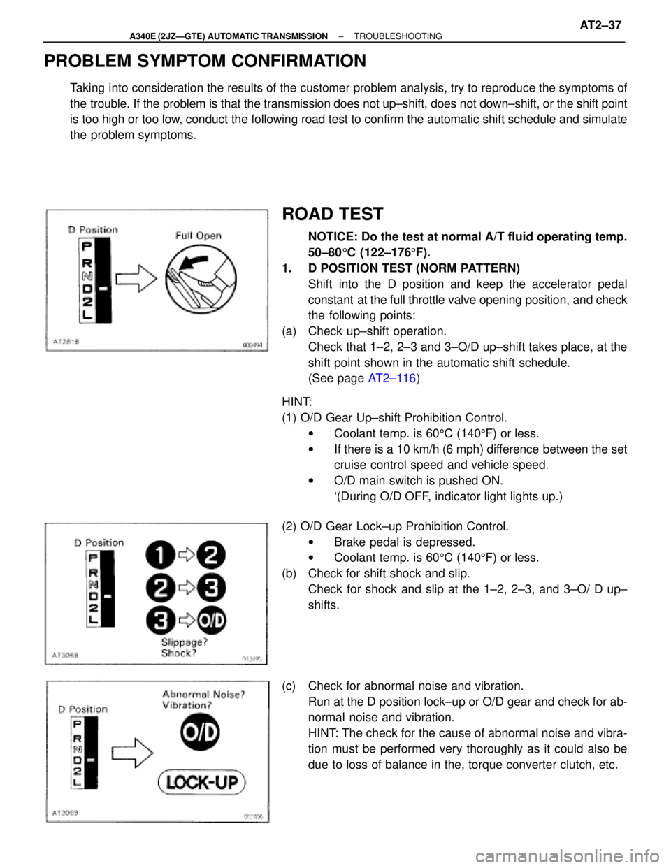
PROBLEM SYMPTOM CONFIRMATION
Taking into consideration the results of the customer problem analysis, try to reproduce the symptoms of
the trouble. If the problem is that the transmission does not up┬▒shift, does not down┬▒shift, or the shift point
is too high or too low, conduct the following road test to confirm the automatic shift schedule and simulate
the problem symptoms.
ROAD TEST
NOTICE: Do the test at normal A/T fluid operating temp.
50┬▒805C (122┬▒1765F).
1. D POSITION TEST (NORM PATTERN)
Shift into the D position and keep the accelerator pedal
constant at the full throttle valve opening position, and check
the following points:
(a) Check up┬▒shift operation.
Check that 1┬▒2, 2┬▒3 and 3┬▒O/D up┬▒shift takes place, at the
shift point shown in the automatic shift schedule.
(See page AT2┬▒116)
HINT:
(1) O/D Gear Up┬▒shift Prohibition Control.
wCoolant temp. is 605C (1405F) or less.
wIf there is a 10 km/h (6 mph) difference between the set
cruise control speed and vehicle speed.
wO/D main switch is pushed ON.
`(During O/D OFF, indicator light lights up.)
(2) O/D Gear Lock┬▒up Prohibition Control.
wBrake pedal is depressed.
wCoolant temp. is 605C (1405F) or less.
(b) Check for shift shock and slip.
Check for shock and slip at the 1┬▒2, 2┬▒3, and 3┬▒O/ D up┬▒
shifts.
(c) Check for abnormal noise and vibration.
Run at the D position lock┬▒up or O/D gear and check for ab-
normal noise and vibration.
HINT: The check for the cause of abnormal noise and vibra-
tion must be performed very thoroughly as it could also be
due to loss of balance in the, torque converter clutch, etc.
± A340E (2JZÐGTE) AUTOMATIC TRANSMISSIONTROUBLESHOOTINGAT2±37
Page 588 of 2543
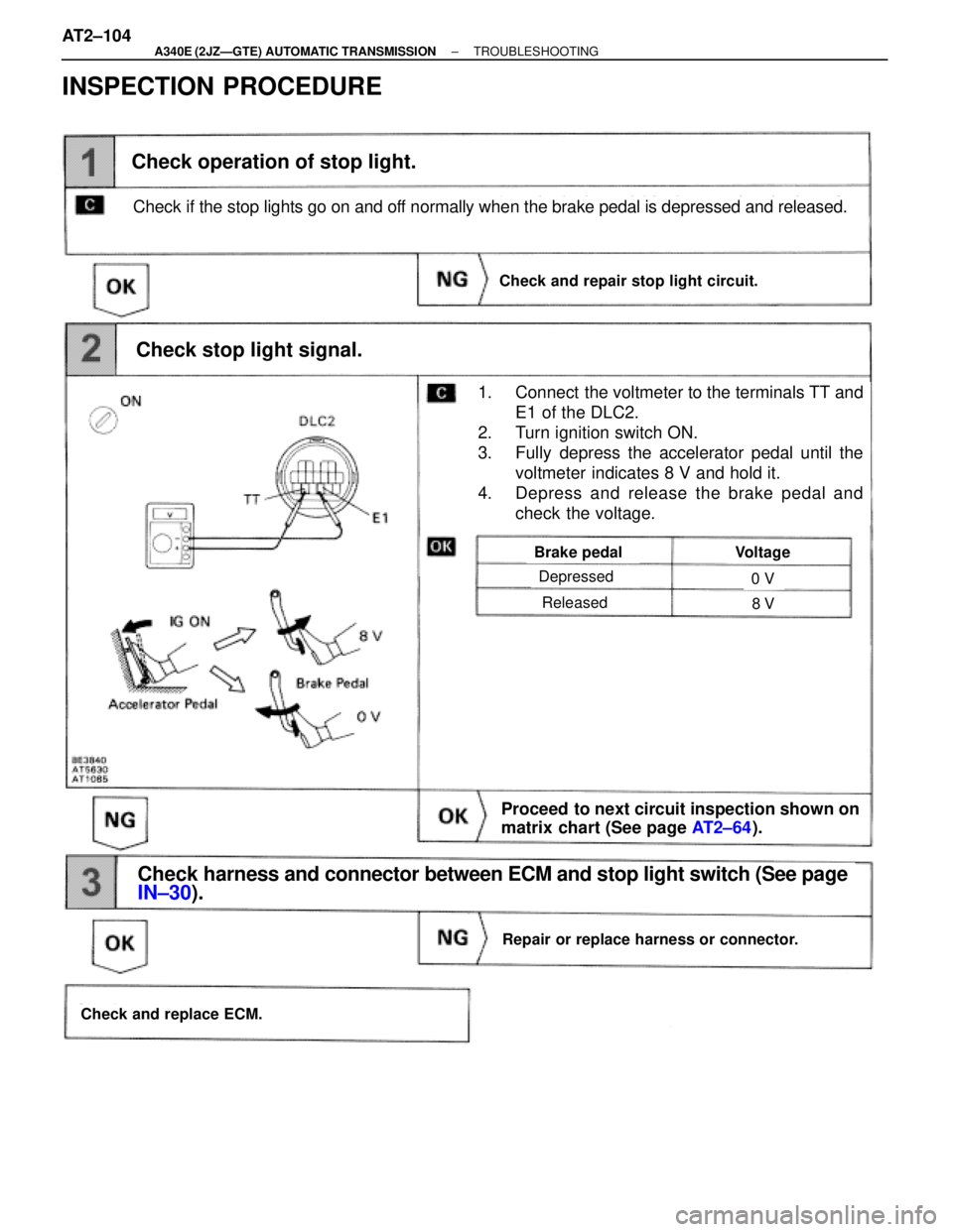
Depressed
Released
Brake pedalVoltage
0 V
8 V
Check stop light signal.
1. Connect the voltmeter to the terminals TT and
E1 of the DLC2.
2. Turn ignition switch ON.
3. Fully depress the accelerator pedal until the
voltmeter indicates 8 V and hold it.
4. Depress and release the brake pedal and
check the voltage.
Proceed to next circuit inspection shown on
matrix chart (See page AT2┬▒64).
Check operation of stop light.
Repair or replace harness or connector.
Check and replace ECM.
Check harness and connector between ECM and stop light switch (See page
IN┬▒30).
Check and repair stop light circuit.
Check if the stop lights go on and off normally when the brake pedal is depressed and released.
INSPECTION PROCEDURE
AT2±104± A340E (2JZÐGTE) AUTOMATIC TRANSMISSIONTROUBLESHOOTING
Page 592 of 2543
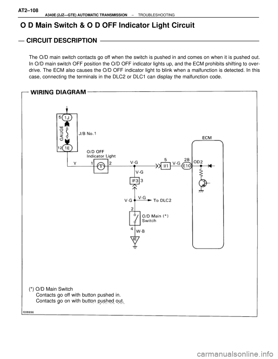
O D Main Switch & O D OFF Indicator Light Circuit
CIRCUIT DESCRIPTION
The O/D main switch contacts go off when the switch is pushed in and comes on when it is pushed out.
In O/D main switch OFF position the O/D OFF indicator lights up, and the ECM prohibits shifting to over-
drive. The ECM also causes the O/D OFF indicator light to blink when a malfunction is detected. In this
case, connecting the terminals in the DLC2 or DLC1 can display the malfunction code.
(*) O/D Main Switch
Contacts go off with button pushed in.
Contacts go on with button pushed out. AT2┬▒108
± A340E (2JZÐGTE) AUTOMATIC TRANSMISSIONTROUBLESHOOTING