cooling TOYOTA tC 2011 Owners Manual (in English)
[x] Cancel search | Manufacturer: TOYOTA, Model Year: 2011, Model line: tC, Model: TOYOTA tC 2011Pages: 473, PDF Size: 10.91 MB
Page 226 of 473
226
3-1. Using the air conditioning system and defogger
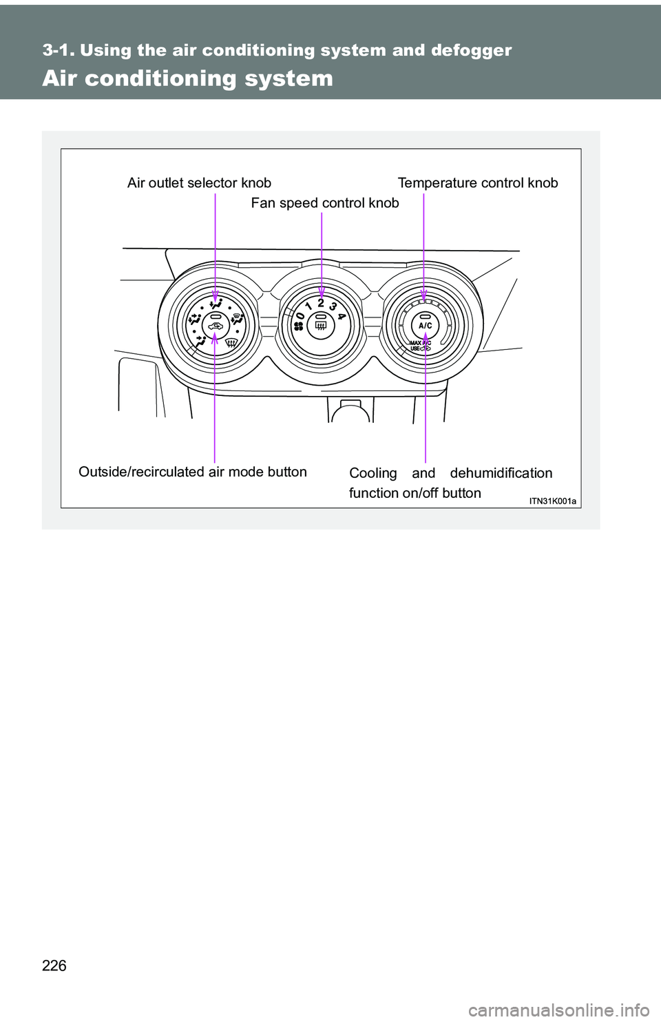
Air conditioning system
Fan speed control knob
Air outlet selector knob
Outside/recirculated air mode button Cooling and dehumidification
function on/off buttonTemperature control knob
Page 229 of 473
229
3-1. Using the air conditioning system
and defogger
3
Interior features
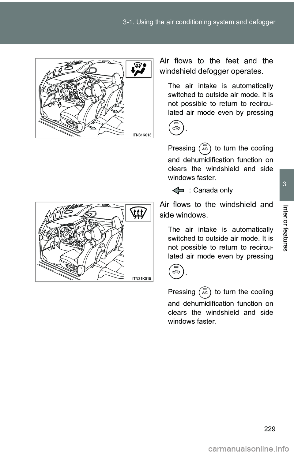
Air flows to the feet and the
windshield defogger operates.
The air intake is automatically
switched to outside air mode. It is
not possible to return to recircu-
lated air mode even by pressing
.
Pressing to turn the cooling
and dehumidification function on
clears the windshield and side
windows faster.
: Canada only
Air flows to the windshield and
side windows.
The air intake is automatically
switched to outside air mode. It is
not possible to return to recircu-
lated air mode even by pressing
.
Pressing to turn the cooling
and dehumidification function on
clears the windshield and side
windows faster.
Page 233 of 473
233
3-1. Using the air conditioning system
and defogger
3
Interior features
■Using the system in recirculated air mode
The windows will fog up more easily if recirculated air mode is used for an
extended period of time.
■ When
is selected for the air outlets used
For your driving comfort, air flowing to the feet may be warmer than air flow-
ing to the upper body depending on the temperature setting.
■ When outside air temperature is below 32 °F (0 °C)
The cooling and dehumidification function may not operate even when
is pressed.
■ Air conditioning odors
●During use, various odors from inside and outside the vehicle may enter
into and accumulate in the air conditioning system. This may then cause
odor to be emitted from the vents.
● To reduce potential odors from occurring:
It is recommended that the air conditioning system be set to outside air
mode prior to turning the vehicle off.
CAUTION
■To prevent the windshield from fogging up
Do not use during cool air operation in extremely humid weather. The
difference between the temperature of the outside air and that of the wind-
shield can cause the outer surface of the windshield to fog up, blocking your
vision.
NOTICE
■To prevent battery discharge
Do not leave the air conditioning system on longer than necessary when the
engine is stopped.
Page 281 of 473
280 4-3. Do-it-yourself maintenance
CAUTION
■When working near the electric c ooling fans or radiator grille
Vehicles without a smart key system
Be sure the engine switch is off. With the engine switch in the “ON” position,
the electric cooling fans may automatically start to run if the air conditioning
is on and/or the coolant temperature is high. ( P. 293)
Vehicles with a smart key system
Be sure the “ENGINE START STOP” switch is off. With the “ENGINE START
STOP” switch in IGNITION ON mode, the electric cooling fans may automat\
-
ically start to run if the air conditioning is on and/or the coolant temperature
is high. ( P. 293)
■ Safety glasses
Wear safety glasses to prevent flying or falling material, fluid spray, etc. from
getting your eyes.
NOTICE
■If you remove the air cleaner filter
Driving with the air cleaner filter removed may cause excessive engine wear
due to dirt in the air. Also, a backfire could cause a fire in the engine com-
partment.
Page 286 of 473
285
4-3. Do-it-yourself maintenance
4
Maintenance and care
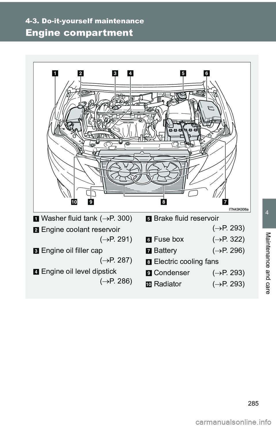
Engine compar tment
Washer fluid tank (P. 300)
Engine coolant reservoir ( P. 291)
Engine oil filler cap ( P. 287)
Engine oil level dipstick ( P. 286)Brake fluid reservoir
( P. 293)
Fuse box ( P. 322)
Battery ( P. 296)
Electric cooling fans
Condenser ( P. 293)
Radiator ( P. 293)
Page 292 of 473
291
4-3. Do-it-yourself maintenance
4
Maintenance and care
Engine coolant
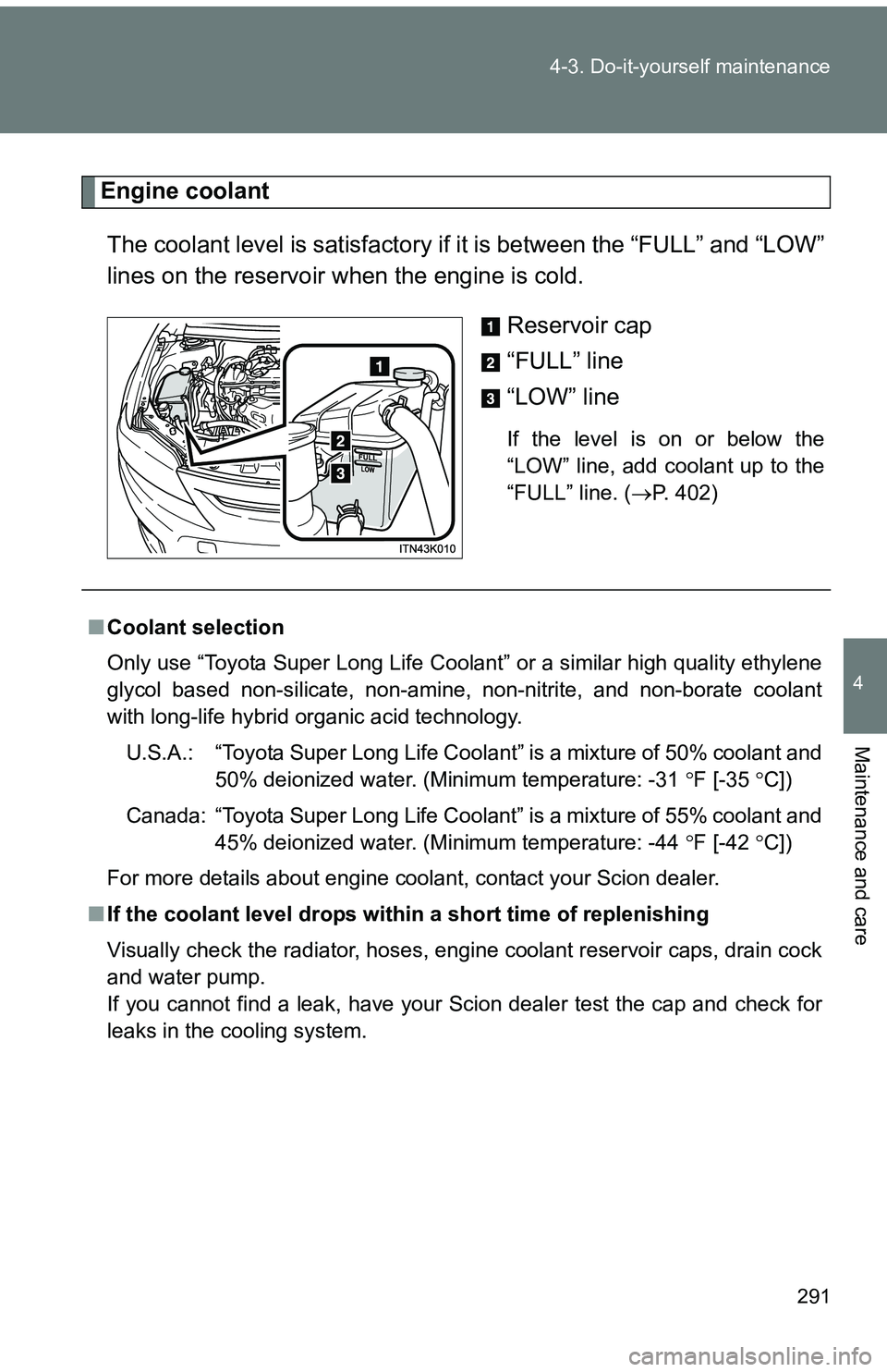
The coolant level is satisfactory if it is between the “FULL” and “LOW”
lines on the reservoir when the engine is cold.
Reservoir cap
“FULL” line
“LOW” line
If the level is on or below the
“LOW” line, add coolant up to the
“FULL” line. (P. 402)
■Coolant selection
Only use “Toyota Super Long Life Coolant” or a similar high quality ethylene
glycol based non-silicate, non-amine, non-nitrite, and non-borate coolant
with long-life hybrid organic acid technology.
U.S.A.: “Toyota Super Long Life Coolant” is a mixture of 50% coolant and 50% deionized water. (Minimum temperature: -31 F [-35 C])
Canada: “Toyota Super Long Life Coolant” is a mixture of 55% coolant and 45% deionized water. (Minimum temperature: -44 F [-42 C])
For more details about engine coolant, contact your Scion dealer.
■ If the coolant level drops within a short time of replenishing
Visually check the radiator, hoses, engine coolant reservoir caps, drain cock
and water pump.
If you cannot find a leak, have your Scion dealer test the cap and check for
leaks in the cooling system.
Page 293 of 473

292 4-3. Do-it-yourself maintenance
CAUTION
■When the engine is hot
Do not remove the engine coolant reservoir cap.
The cooling system may be under pressure and may spray hot coolant if the
cap is removed, causing burns or other injuries.
NOTICE
■When adding coolant
Coolant is neither plain water nor stra ight antifreeze. The correct mixture of
water and antifreeze must be used to provide proper lubrication, corrosion
protection and cooling. Be sure to read the antifreeze or coolant label.
■ If you spill coolant
Be sure to wash it off with water to prevent damaging parts or paint.
Page 326 of 473
325
4-3. Do-it-yourself maintenance
4
Maintenance and care
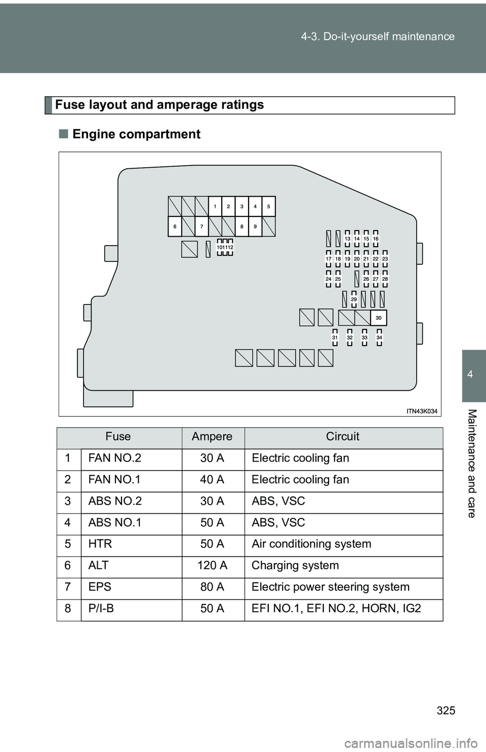
Fuse layout and amperage ratings
■ Engine compartment
FuseAmpereCircuit
1
FAN NO.230 AElectric cooling fan
2 FAN NO.1 40 A Electric cooling fan
3 ABS NO.2 30 A ABS, VSC
4 ABS NO.1 50 A ABS, VSC
5 HTR 50 A Air conditioning system
6 ALT 120 A Charging system
7 EPS 80 A Electric power steering system
8 P/I-B 50 A EFI NO.1, EFI NO.2, HORN, IG2
Page 331 of 473
330 4-3. Do-it-yourself maintenance
14 ACC5 ABody ECU, clock, outside rear view
mirror, shift lock system, audio sys-
tem
15 IG 5 ARear window defoggers, electric
cooling fan, multiport fuel injection
system/sequential multiport fuel
injection system
16 TAIL 10 AParking lights, tail lights, side
marker lights, license plate lights,
multiport fuel injection system/
sequential multiport fuel injection
system
17 IGN 7.5 AMultiport fuel injection system/
sequential multiport fuel injection
system, automatic transmission,
clock, smart key system, steering
lock system, SRS airbag system,
fuel pump, front passenger occu-
pant classification system
18 PANEL 5 AGauges and meters, air condition-
ing system, seat heater, VSC OFF
switch, shift lever illumination,
steering switch, clock, audio sys-
tem
19 S/HTR FL 10 A Seat heater (driver’s side)
20 MET 7.5 A Gauges and meters
FuseAmpereCircuit
Page 402 of 473
5
When trouble arises
401
5-2. Steps to take in an emergency
NOTICE
■
When handling jumper cables
When connecting the jumper cables, ensure that they do not become entan-
gled in the cooling fans or belt.