height TOYOTA TERCEL 1985 Repair Manual
[x] Cancel search | Manufacturer: TOYOTA, Model Year: 1985, Model line: TERCEL, Model: TOYOTA TERCEL 1985Pages: 885, PDF Size: 64.52 MB
Page 476 of 885
PR-z PROPELLER SHAFT - Precautions, Troubleshooting, Propeller Shaft
PRECAUTIONS
1. As the universal ioint is a non-disassembly type' the
propeller shaft or intermediate shaft must be replaced
as an assembly in the event of universalioint trouble.
2. Be careful not to grip the propeller shaft tube too tight-
ly in the vise as this will cause deformation.
TROUBLESHOOTING
ProblemPossible causeRemedyPage
NoiseSleeve yoke spline worn
Center bearing worn
Spider bearing worn or stuck
Replace intermediate shaft
Replace center bearing
Replace intermediate shaft or
propeller shaft
PR-3
PR-3
PR-3
VibrationPropeller shaft runout
Propeller shaft unbalance
Transmission extension housing rear
bushing worn
Sleeve yoke spline stuck
Center bearing height imProPer
Replace propeller shaft
Balance propeller shaft
Replace bushing
Replace intermediate shaft
Adjust bearing height
PR-3
PR-3
TA.4O
PR-3
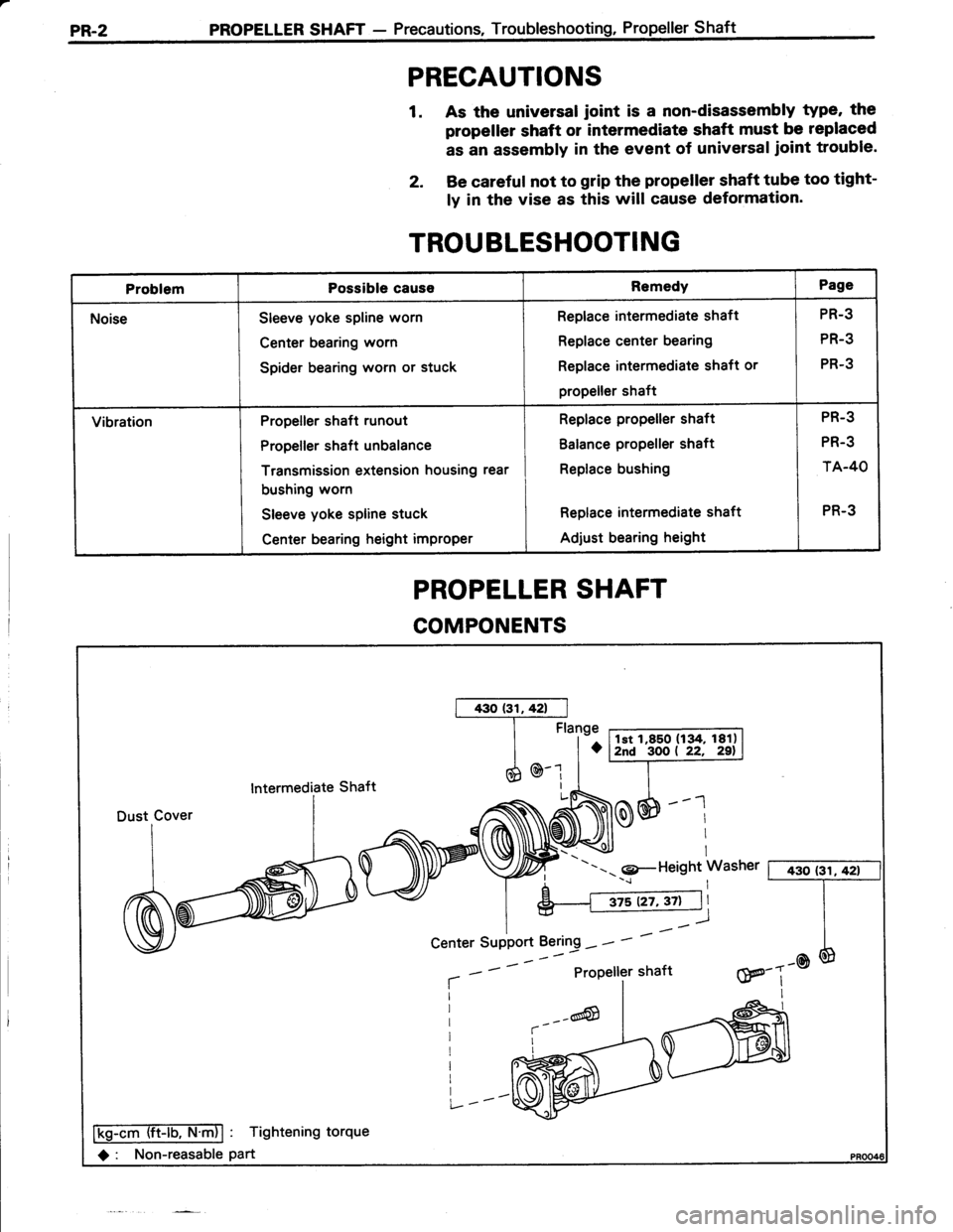
PROPELLER SHAFT
COMPONENTS
lntermediate Shaft
---- 9-Height Washer [ 430 (3il42t
aProPeller shaftw---@III
Ffiffiiib-ntnl : Tightening torque
O : Non-reasable part
Center SuPPort Bering - -
Page 480 of 885
PR-6 PROPELLER SHAFT - Propeiler Shaft
SST
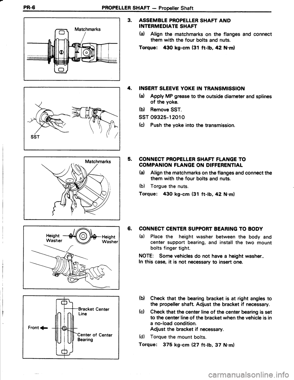
3. ASSEMBTE PROPELLER SHAFT AND
INTERMEDIATE SHAFT
(a) Align the matchmarks on the flanges and connect
them with the four bolts and nuts.
Torque: 430 kg-cm (31 ft-|b,42 N.ml
4, INSERT SLEEVE YOKE IN TRANSMISSION
{a) Apply MP grease to the outsade diameter and splines
of the yoke.
(b) Remove SST.
ssT 09325-12010
(c) Push the yoke into the transmission.
5. CONNECT PROPELLER SHAFT FLANGE TO
COMPANION FLANGE ON DIFFERENTIAL
(a) Align the matchmarks on the flanges and connect the
them with the four bolts and nuts.
(b) Torgue the nuts.
Torque: 43O kg-cm (31 ft-tb,42 N.m)
6. CONNECT CENTER SUPPORT BEARING TO BODY
ta) Place the height washer between the body and
center support bearing, and install the two mount
bolts finger tight.
NOTE: Some vehicles do not have a height washer..
In this case, it is not necessary to insert one.
(b) Check that the bearing bracket is at right angles to
the propeller shaft Adjust the bracket if necessary.
(c) Check that the center line of the center bearing is set
to the center line of the bracket when the vehicle is in
a no-load condition.
Adjust the bracket if necessary.
(d) Torque the mount bolts.
Torque: 375 kg-cm Q7 tt-ab,37 N.m)
Front 1-
Center of CenterBearing
Page 483 of 885
FRONT AXLE AND SUSPENSION - Front Wheel AlignmentFA-3
FRONT WHEEL ALIGNMENT
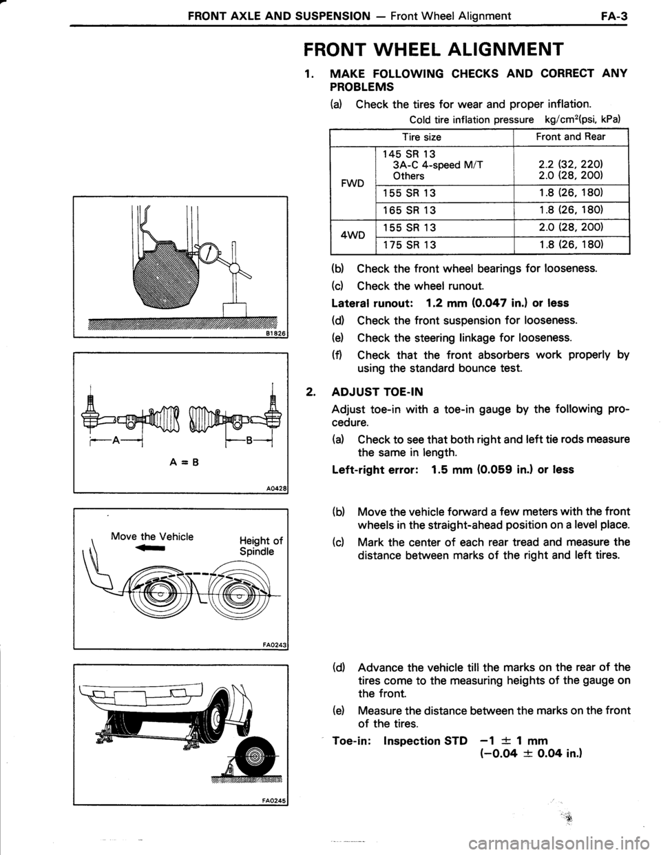
1. MAKE FOLLOWING CHECKS AND CORRECT ANY
PROBLEMS
(d Check the tires for wear and proper inflation.
Cold tire inflation pressure kg/cm2(psi, kPa)
Tire sizeFront and Rear
FWD
145 SR 13
3A-C 4-speed M/T
Others
2.2 (32.220l.
2.O Q8,2001
155 SR 131.8(26. 180)
165 SR131 .8 (26, 180)
4WD155 SR 132.O Q8,2001
175 SR 131 .8 (26. 180)
(b) Check the front wheel bearings for looseness.
(d Check the wheel runout.
Lateral runout: 1.2 mm (0.047 in.) or less
(d) Check the front suspension for looseness.
(e) Check the steering linkage for looseness.
(f) Check that the front absorbers work properly by
using the standard bounce test.
ADJUST TOE.IN
Adjust toe-in with a toe-in gauge by the following pro-
cedure.
(d Check to see that both right and left tie rods measure
the same in length.
Left-right error: 1.5 mm (0.059 in.l or less
Move the vehicle forward a few meters with the front
wheels in the straight-ahead position on a level place.
Mark the center of each rear tread and measure the
distance between marks of the right and left tires.
(d) Advance the vehicle till the marks on the rear of the
tires come to the measuring heights of the gauge on
the front.
(e) Measure the distance between the marks on the front
of the tires.
Toe-in: lnspection STD -1 {- 1 mm(-0.O4 + O.O4 in.)
AA
+=ruf,ffi Wry@=S
--A-- F--B--i
A=B
2.
(b)
(c)
!,.-!'ru,
Page 485 of 885
FRONT AXLE AND SUSPENSION - Front Wheel AlignmentFA-5
Front Rear (FWDI
Rear (4WD)
More Camber
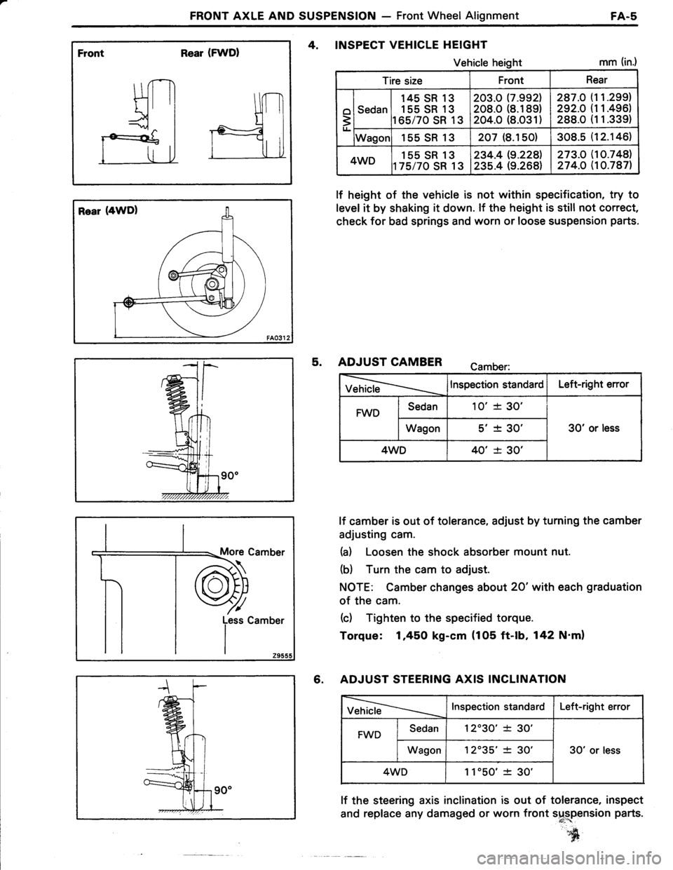
4, INSPECT VEHICLE HEIGHT
Vehicle heightmm (in.)
lf height of the vehicle is not within specification, try to
level it by shaking it down. lf the height is still not correct,
check for bad springs and worn or loose suspension parts.
5. ADJUST CAMBER camber:
VehicleInspection standardLeft-right error
FWDSedan10'+ 30'
30' or lessWagons'� + 30'�
4WD40' -t- 30'
lf camber is out of tolerance, adjust by turning the camber
adjusting cam.
(a) Loosen the shock absorber mount nut.
(b) Turn the cam to adjust.
NOTE: Camber changes about 20'with each graduation
of the cam.
(c) Tighten to the specified torque.
Torque: 1,45O kg-cm {105 ft-lb, 142 N'm)
6. ADJUST STEERING AXIS INCLINATION
VehicleInspection standardLeft-right error
FWDSedan12'30'�* 30'
30' or lessWagon12035'�+ 30'�
4WD1 1'50'� -t- 30'
lf the steering axis inclination is out of tolerance, inspect
and replace any damaged or worn front s$rplnsion parts.
s[
Tire sizeFrontRear
o
3
Sedan
145 SR 13
155 SR 13
165/70 SR 13
203.0 17.9921208.0 (8.189)
204.0 (8.O31)
287.O
292.O
288.0
1 1.299)
11.496)
1 1.339)
Wagor155SR13207 (8.150)308.512.146l.
4WD155 SR 13
t75/70 SR 13
234.419.2281
235.4 (9.268)273.O274.O
10.748)10.787)
Page 503 of 885
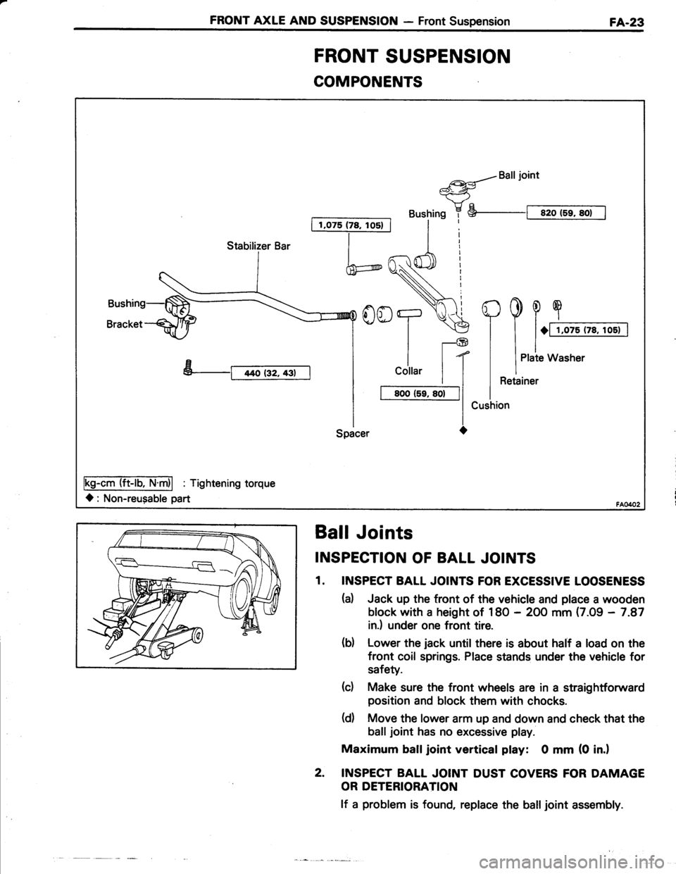
FRONT AXLE AND SUSPENSION - Front SuspensionFA-23
COMPONENTS
I 1,075 (78, los) |
a{Balljoint*-<-ry"
Bushing 7 S--t sro (5r, sot I
h
YooT.\€
ll-@
| | t(
I
cottar | |
I t BooCr, so-|l
l-lSpacer O
Fs-AmTliET'fri| : Tishtenins torque
l: Non-reugable part
Stabilizer Bar
FRONT SUSPENSION
Ball Joints
INSPECTION OF BALL JOINTS
1. INSPECT BALL JOINTS FOR EXCESSIVE LOOSENESS
(d Jack up the tront of the vehicle and place a wooden
block with a height of 18O - 2OO mm (7.09 - 7.87
in.) under one front tire.
(d Lower the jack until there is about half a load on the
front coil springs. Place stands under the vehicle for
safety.
(c) Make sure the front wheels are in a straightforward
position and block them with chocks.
(d) Move the lower arm up and down and check that the
balljoint has no excessive play.
Maximum balljoint vertical play: 0 mm (0 in.l
2. INSPECT BALL JOINT DUST COVERS FOR DAMAGE
OR DETERIORATION
lf a problem is found, replace the balljoint assembly.
Page 565 of 885
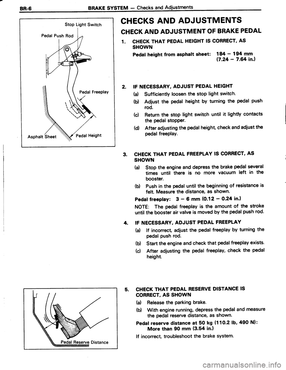
Stop Light Switch
Pedal Push Rod
Pedal Freeplay
Asphalt SheetPedat Height
BRAKE SYSTEM - Checks and
CHECKS AND ADJUSTMENTS
CHECK AND ADJUSTMENT OF BRAKE PEDAL
1. CHECK THAT PEDAL HEIGHT IS CORRECT' AS
SHOWN
Pedat heisht from asphalt slreet:
i#;:?ifil.,
IF NECESSARY. ADJUST PEDAL HEIGHT
(a) Sufficiently loosen the stop light switch.
(b) Adjust the pedal height by turning the pedal push
rod.
(c) Return the stop light switch until it lightly contacts
the pedal stopper.
(d) After adjusting the pedal height, check and adiust the
pedal freePlay.
CHECK THAT PEDAL FREEPLAY IS CORRECT, AS
SHOWN
(a) Stop the engine and depress the brake pedal several
times until there is no more vacuum left in the
booster.
(b) Push in the pedal until the beginning of resistance is
felt. Measure the distance, as shown'
Pedaf freepfay: 3 - 6 mm (0.12 - O,24 in.l
NOTE: The pedal freeplay is the amount of the stroke
until the booster air valve is moved by the pedal push rod.
IF NECESSARY, ADJUST PEDAL FREEPLAY
(a) lf incorrect adiust the pedal freeplay by turning the
pedal Push rod.
(b) Start the engine and check that pedal freeplay exists.
(c) After adjusting the pedal freeplay, check the pedal
height.
CHECK THAT PEDAL RESERVE DISTANCE IS
CORRECT, AS SHOWN
(a) Release the parking brake.
(b) With engine running, depress the pedal and measure
the pedal reserve distance, as shown.
Pedaf reserve distance at 50 kg (1 1 O-2 1b,490 Nl:
More than 90 mm (3.54 in.l
lf incorrect, troubleshoot the brake system.