TOYOTA TERCEL 1996 Service Repair Manual
TERCEL 1996
TOYOTA
TOYOTA
https://www.carmanualsonline.info/img/14/57471/w960_57471-0.png
TOYOTA TERCEL 1996 Service Repair Manual
Trending: transmission oil, height, engine coolant, Seats, seat memory, width, connecting rod torque
Page 1111 of 1202

BO343-01
BO4420
AdhesiveAdhesive
N00141
Adhesive Primer M
Primer M
Primer M
Z16119
Primer G
Primer G
BO4422
BO-40
- BODYQUARTER WINDOW GLASS
1996 TERCEL (RM440U)
INSTALLATION
1. CLEAN AND SHAPE CONTACT SURFACE OF BODY
(a) Using a knife, cut away any rough areas on the body.
HINT:
Leave as much of the adhesive on the body as possible.
(b) Clean the cutting surface of the adhesive with a piece of
shop rag saturated in cleaner.
HINT:
Even if all the adhesive has been removed, clean the body.
2. CLEAN REMOVED GLASS BEFORE INSTALLATION
(a) Using a scraper, remove the adhesive sticking to the
glass.
(b) Clean the glass with cleaner.
NOTICE:
Do not touch the glass after cleaning it.
3. COAT CONTACT SURFACE OF BODY WITH PRIMER
ºMº
Using a brush, coat the contact on the body with Primer M.
NOTICE:
�Let the primer coating dry for 3 minutes or more.
�Do not coat Primer M to the adhesive.
�Do not keep any of the opened Primer M for later use.
4. COAT CONTACT SURFACE OF GLASS WITH PRIMER
ºGº
(a) Using a brush or sponge, coat the edge of the glass and
the contact surface with Primer G.
(b) Wipe it off with a clean shop rag before the primer dries.
NOTICE:
�Let the primer coating dry for 3 minutes or more.
�Do not keep any of the opened Primer G for later use.
5. MIX ADHESIVE COATING
NOTICE:
Be sure that installation of the moulding is finished within
the adhesive's usable time.
(a) Thoroughly clean the glass plate and putty spatula with
solvent.
(b) Thoroughly mix 500 g (17.64 oz.) of the main agent and
75 g (2.65 oz.) of the hardening agent on a glass plate or
similar object with a putty spatula.
Page 1112 of 1202
N12283
a - a b - bab
H ab
H
- BODYQUARTER WINDOW GLASS
BO-41
1996 TERCEL (RM440U)
6. APPLY ADHESIVE
(a) Cut off the tip of the cartridge nozzle. Fill the cartridge with
adhesive.
(b) Load the cartridge into the sealer gun.
(c) Coat the glass with adhesive, as shown.
H: 12 mm (0.47 in.)
7. INSTALL QUARTER WINDOW GLASS
(a) Install the glass to the body.
(b) Use adhesive tape to keep the glass tight against the
body.
8. INSPECT FOR LEAKS AND REPAIR
(a) Perform a leak test after the hardening time has elapsed.
(b) Seal any leak with sealant.
Part No.08833-00030 or equivalent.
9. INSTALL ROOF SIDE INNER GARNISH
10. INSTALL FRONT DOOR SCUFF PLATE
11. INSTALL QUARTER TRIM BOARD
12. INSTALL REAR SEAT OUTER BELT
Torque: 43 N´m (440 kgf´cm, 32 ft´lbf)
13. INSTALL PACKAGE TRAY TRIM SIDE COVER
14. INSTALL FRONT SEAT OUTER BELT
Torque: 43 N´m (440 kgf´cm, 32 ft´lbf)
15. INSTALL REAR SEAT BECK
Torque: 18 N´m (185 kgf´cm, 13 ft´lbf)
16. INSTALL REAR SEAT CUSHION
Page 1113 of 1202
BO344-01
N15579
Back Window GlassBack Window Moulding
Package Tray Trim
High Mounted Stop Light Package Tray Trim Side Cover
Rear Seat Cushion
Rear Seatback Roof Side Inner Garnish
Quarter Trim Board
BO-42
- BODYBACK WINDOW GLASS
1136 Author�: Date�:
1996 TERCEL (RM440U)
BACK WINDOW GLASS
COMPONENTS
Page 1114 of 1202
BO345-01
N12301
- BODYBACK WINDOW GLASS
BO-43
1996 TERCEL (RM440U)
REMOVAL
1. DISCONNECT DEFOGGER CONNECTOR
2. REMOVE REAR SEAT CUSHION AND SEATBACK
3. REMOVE REAR SEAT BELT
4. REMOVE FRONT DOOR SCUFF PLATE
5. REMOVE QUARTER TRIM BOARD
6. REMOVE FRONT SEAT BELT
7. REMOVE HIGH MOUNTED STOP LIGHT
8. REMOVE PACKAGE TRAY GARNISH
9. REMOVE BACK WINDOW MOULDING
Using a knife, cut off the body.
NOTICE:
Do not damage the body with the knife.
10. REMOVE BACK WINDOW GLASS
Remove the glass in the same manner as windshield (See page
BO-34).
Page 1115 of 1202

BO346-01
N12302
BO-44
- BODYBACK WINDOW GLASS
1996 TERCEL (RM440U)
INSTALLATION
1. CLEAN AND SHAPE CONTACT SURFACE OF BODY
(See page BO-35)
2. CLEAN REMOVED GLASS (See page BO-35)
3. POSITION GLASS (See page BO-35)
4. CLEAN CONTACT SURFACE GLASS (See page
BO-35)
5. COAT CONTACT SURFACE OF BODY WITH PRIMER
ºMº (See page BO-35)
6. COAT CONTACT SURFACE OF GLASS WITH PRIMER
ºGº (See page BO-35)
7. MIX ADHESIVE COATING (See page BO-35)
8. APPLY ADHESIVE (See page BO-35)
9. INSTALL GLASS (See page BO-35)
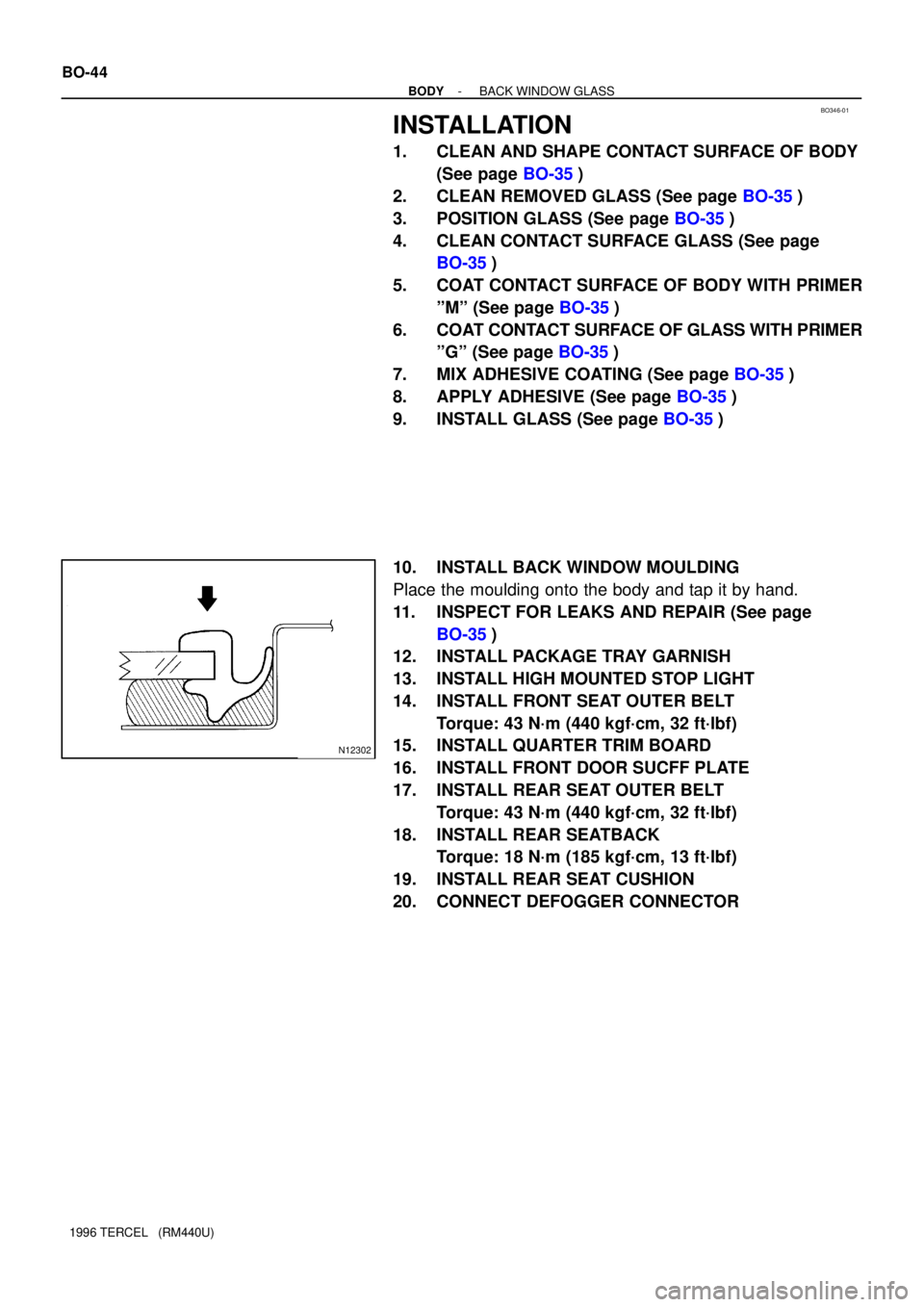
10. INSTALL BACK WINDOW MOULDING
Place the moulding onto the body and tap it by hand.
11. INSPECT FOR LEAKS AND REPAIR (See page
BO-35)
12. INSTALL PACKAGE TRAY GARNISH
13. INSTALL HIGH MOUNTED STOP LIGHT
14. INSTALL FRONT SEAT OUTER BELT
Torque: 43 N´m (440 kgf´cm, 32 ft´lbf)
15. INSTALL QUARTER TRIM BOARD
16. INSTALL FRONT DOOR SUCFF PLATE
17. INSTALL REAR SEAT OUTER BELT
Torque: 43 N´m (440 kgf´cm, 32 ft´lbf)
18. INSTALL REAR SEATBACK
Torque: 18 N´m (185 kgf´cm, 13 ft´lbf)
19. INSTALL REAR SEAT CUSHION
20. CONNECT DEFOGGER CONNECTOR
Page 1116 of 1202
BO1IC-04
N15778
No.2 Heater to
Register Duct
Center Heater to
Register Duct
Instrument Panel Reinforcement
AG
AA
G
G
G
G
G
G
A
A Instrument Panel
Brace No.1
Instrument Panel
Brace No.2
Clock Hole Cover
C
CInstrument Panel
Heater
Control
B
B
B
B
DDD
Lower Center Finish Panel
Center Upper
Cluster Finish Panel
Combination
Mater
Steering Column Cover
Front Pillar Garnish
Combination Switch
Cowl Side
Trim
Front Door
Scuff Plate
Instrument Panel
Lower Pad
Lower Center Finish Panel
Steering Wheel
Center Cluster
Finish Panel
Shifting Hole
Bezel
F
F
Ash Receptacle BoxD
D
D
D
Console Box
Lower Instrument Cover
BB
BBHeater Control Panel
Knob
- BODYINSTRUMENT PANEL
BO-45
1139 Author�: Date�:
1996 TERCEL (RM440U)
INSTRUMENT PANEL
COMPONENTS
Page 1117 of 1202
N15580
Defroster Nozzle
E
EE
E
E
No.1 Heater to
Register Duct
E
E
E
No.3 Heater to Register Duct
Instrument Panel Wire
Airbag Door
No.1 RegisterE
E
No.2 RegisterEE
E
ED
DDD
Center Bracket
Lower RH Panel
Lower LH Panel
Front Passenger Airbag Assembly
No.3 Register
E
E BO-46
- BODYINSTRUMENT PANEL
1140 Author�: Date�:
1996 TERCEL (RM440U)
Page 1118 of 1202
V06938
ED
A
G
BC
F
H Code Shape Size
ù = 8
(0.31)
L = 15
(0.59)Code Shape Size Code Shape Size
ù = 5
(0.20)
L = 16
(0.63)
ù = 8
(0.31)ù = 5
(0.24)
L = 22
(0.87)
ù = 5
(0.20)
L = 14
(0.55)
ù = 6
(0.24)ù = 6
(0.24)
L = 20
(0.55)
ù = 5
(0.20)
L = 12
(0.47)mm (in.)
- BODYINSTRUMENT PANEL
BO-47
1141 Author�: Date�:
1996 TERCEL (RM440U)
HINT:
Screw shapes and sizes are indicated in the table below. The codes (A-H) correspond to those indicated
on the previous pages.
Page 1119 of 1202

BO347-01
N12292
N12291
N12055
BO-48
- BODYINSTRUMENT PANEL
1996 TERCEL (RM440U)
REMOVAL
1. REMOVE FRONT PILLAR GARNISHES
2. REMOVE COWL SIDE TRIMS
3. REMOVE FRONT DOOR SCUFF PLATES
4. REMOVE STEERING WHEEL (See page SR-13)
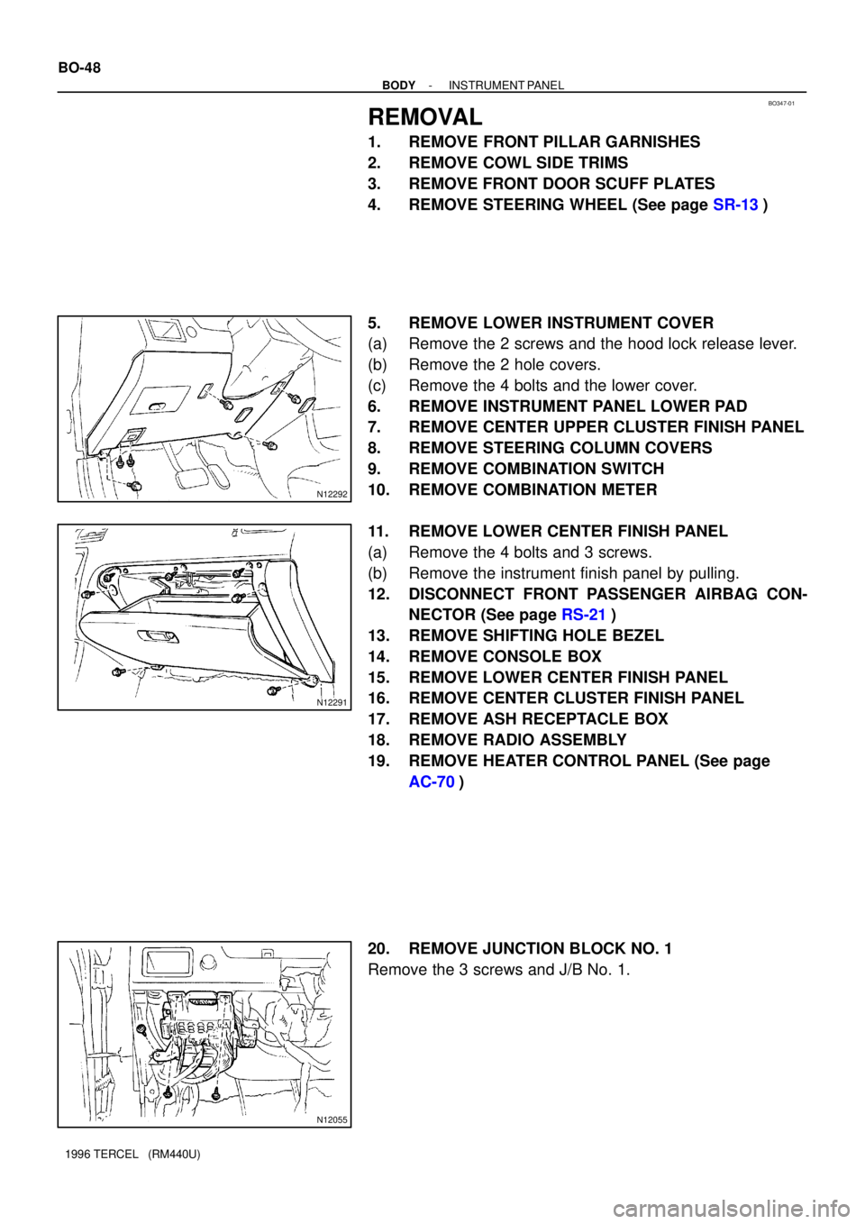
5. REMOVE LOWER INSTRUMENT COVER
(a) Remove the 2 screws and the hood lock release lever.
(b) Remove the 2 hole covers.
(c) Remove the 4 bolts and the lower cover.
6. REMOVE INSTRUMENT PANEL LOWER PAD
7. REMOVE CENTER UPPER CLUSTER FINISH PANEL
8. REMOVE STEERING COLUMN COVERS
9. REMOVE COMBINATION SWITCH
10. REMOVE COMBINATION METER
11. REMOVE LOWER CENTER FINISH PANEL
(a) Remove the 4 bolts and 3 screws.
(b) Remove the instrument finish panel by pulling.
12. DISCONNECT FRONT PASSENGER AIRBAG CON-
NECTOR (See page RS-21)
13. REMOVE SHIFTING HOLE BEZEL
14. REMOVE CONSOLE BOX
15. REMOVE LOWER CENTER FINISH PANEL
16. REMOVE CENTER CLUSTER FINISH PANEL
17. REMOVE ASH RECEPTACLE BOX
18. REMOVE RADIO ASSEMBLY
19. REMOVE HEATER CONTROL PANEL (See page
AC-70)
20. REMOVE JUNCTION BLOCK NO. 1
Remove the 3 screws and J/B No. 1.
Page 1120 of 1202
N12054
N12053
- BODYINSTRUMENT PANEL
BO-49
1996 TERCEL (RM440U)
21. REMOVE NO. 2 HEATER TO REGISTER DUCT
Remove the clip and the duct.
22. REMOVE CLOCK HOLE COVER
Using a screwdriver, remove the clock then disconnect the con-
nector.
HINT:
Tape the screwdriver tip before use.
23. REMOVE INSTRUMENT PANEL
Remove the 4 bolts, nuts and the instrument panel.
24. CENTER HEATER TO REGISTER DUCT
25. INSTRUMENT PANEL BRACE NO. 1
26. INSTRUMENT PANEL BRACE NO. 2
27. INSTRUMENT PANEL REINFORCEMENT
Trending: brake light, hood release, piston bearing torque, fuel tank removal, key battery, generator adjusting lever, keyless


