display TOYOTA TUNDRA 2016 2.G Owner's Manual
[x] Cancel search | Manufacturer: TOYOTA, Model Year: 2016, Model line: TUNDRA, Model: TOYOTA TUNDRA 2016 2.GPages: 588, PDF Size: 13.44 MB
Page 211 of 588
2114-5. Using the driving support systems
4
Driving
Rear view monitor system
Vehicles with Entune Audio Plus or Entune Premium Audio
(Multimedia system types: P. 254)
Refer to the “NAVIGATION SYSTEM OWNER’S MANUAL”.
Vehicles with Entune Audio (Multimedia system types: P. 254)
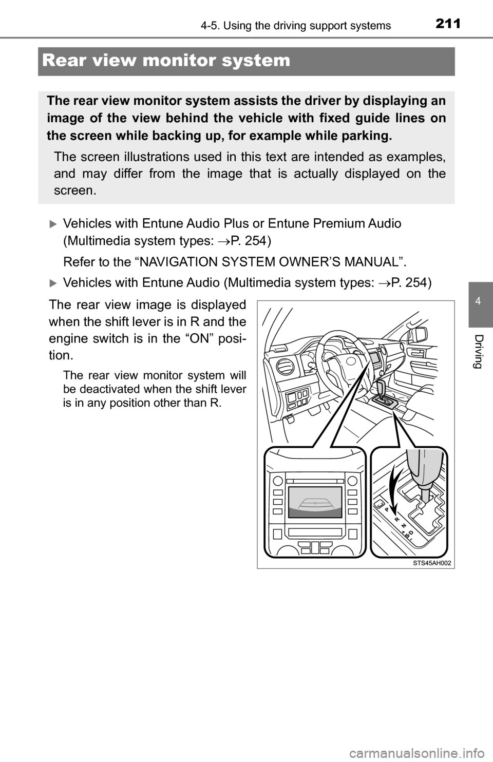
The rear view image is displayed
when the shift lever is in R and the
engine switch is in the “ON” posi-
tion.
The rear view monitor system will
be deactivated when the shift lever
is in any position other than R.
The rear view monitor system assists the driver by displaying an
image of the view behind the veh icle with fixed guide lines on
the screen while backing up, for example while parking.
The screen illustrations used in this text are intended as examples,
and may differ from the image that is actually displayed on the
screen.
Page 212 of 588
2124-5. Using the driving support systems
■Screen description
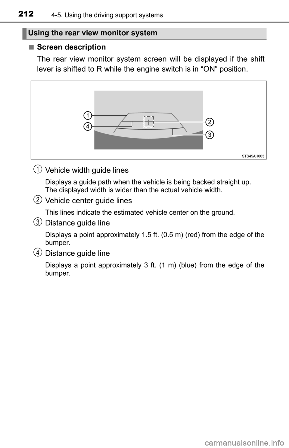
The rear view monitor system scr een will be displayed if the shift
lever is shifted to R while the eng ine switch is in “ON” position.
Vehicle width guide lines
Displays a guide path when the vehicle is being backed straight up.
The displayed width is wider than the actual vehicle width.
Vehicle center guide lines
This lines indicate the estimated vehicle center on the ground.
Distance guide line
Displays a point approximately 1.5 ft. (0.5 m) (red) from the edge of the
bumper.
Distance guide line
Displays a point approximately 3 ft. (1 m) (blue) from the edge of the
bumper.
Using the rear view monitor system
1
2
3
4
Page 213 of 588
2134-5. Using the driving support systems
4
Driving
■Area displayed on screen
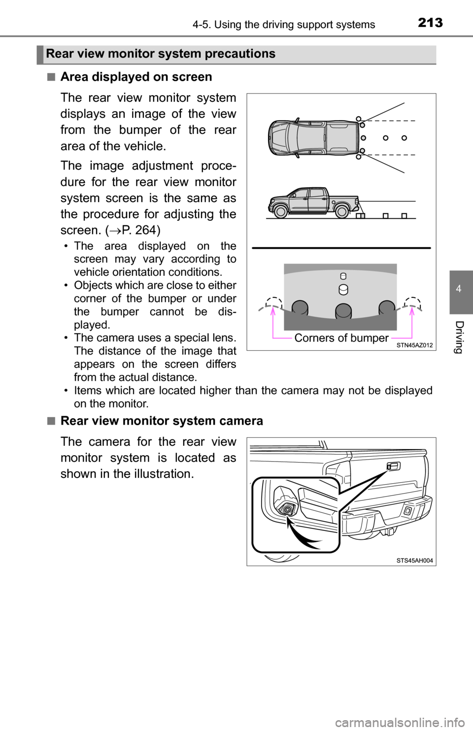
The rear view monitor system
displays an image of the view
from the bumper of the rear
area of the vehicle.
The image adjustment proce-
dure for the rear view monitor
system screen is the same as
the procedure for adjusting the
screen. (P. 264)
• The area displayed on the
screen may vary according to
vehicle orientation conditions.
• Objects which are close to either corner of the bumper or under
the bumper cannot be dis-
played.
• The camera uses a special lens. The distance of the image that
appears on the screen differs
from the actual distance.
• Items which are located higher than the camera may not be displayed
on the monitor.
■
Rear view monitor system camera
The camera for the rear view
monitor system is located as
shown in the illustration.
Rear view monitor system precautions
Corners of bumper
Page 215 of 588
2154-5. Using the driving support systems
4
Driving
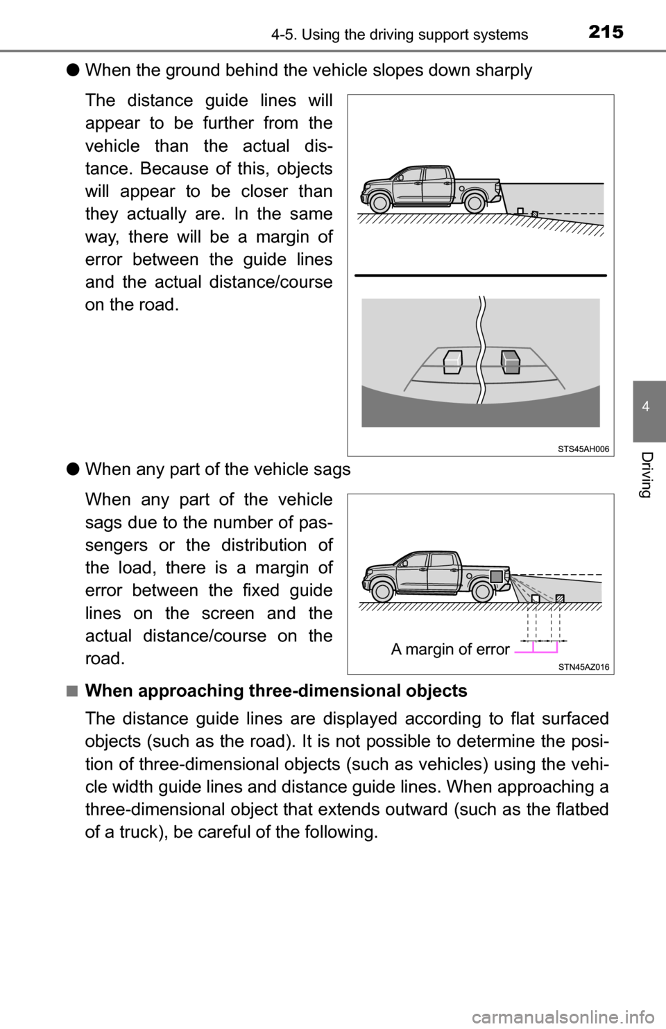
●When the ground behind the vehi cle slopes down sharply
The distance guide lines will
appear to be further from the
vehicle than the actual dis-
tance. Because of this, objects
will appear to be closer than
they actually are. In the same
way, there will be a margin of
error between the guide lines
and the actual distance/course
on the road.
● When any part of the vehicle sags
When any part of the vehicle
sags due to the number of pas-
sengers or the distribution of
the load, there is a margin of
error between the fixed guide
lines on the screen and the
actual distance/course on the
road.
■When approaching thre e-dimensional objects
The distance guide lines are displayed according to flat surfaced
objects (such as the road). It is not possible to determine the posi-
tion of three-dimensional objects (s uch as vehicles) using the vehi-
cle width guide lines and distance guide lines. When approaching a
three-dimensional object that extends outward (such as the flatbed
of a truck), be careful of the following.
A margin of error
Page 218 of 588
2184-5. Using the driving support systems
CAUTION
■When using the rear view monitor system
The rear view monitor system is a supplemental device intended to assist
the driver when backing up. When backing up, be sure to visually check all
around the vehicle both directly and using the mirrors before proceeding.
Observe the following precautions to avoid an accident that could result in
death or serious injuries.
● Never depend on the rear view monitor system entirely when backing up.
The image and the position of the guide lines displayed on the screen may
differ from the actual state.
Use caution, just as you would when backing up any vehicle.
● Be sure to back up slowly, depressing the brake pedal to control vehicle
speed.
● The instructions given are only guide lines.
When and how much to turn the steering wheel will vary according to traf-
fic conditions, road surface conditions, vehicle condition, etc. when park-
ing. It is necessary to be fully aware of this before using the rear view
monitor system.
● When parking, be sure to check that the parking space will accommodate
your vehicle before maneuvering into it.
● Do not use the rear view monitor system in the following cases:
• On icy or slick road surfaces, or in snow
• When using tire chains or emergency tires
• When the tailgate is not closed completely
• On roads that are not flat or straight, such as curves or slopes.
● In low temperatures, the screen may darken or the image may become
faint. The image could distort when the vehicle is moving, or you may
become unable to see the image on the screen. Be sure to visually check
all around the vehicle both directly and using the mirrors before proceed-
ing.
● If the tire sizes are changed, the position of the fixed guide lines displayed
on the screen may change.
● The camera uses a special lens. The distances between objects and
pedestrians that appear in the image displayed on the screen will differ
from the actual distances. ( P. 214)
Page 221 of 588
2214-5. Using the driving support systems
4
Driving
Rear Cross Traffic Alert buzzer (Rear Cross Traffic Alert function
only)
When a vehicle approaching from the right or left rear of the vehicle is
detected, a buzzer sounds from behind the left-hand rear pillar.
■ The outside rear view mi rror indicators visibility
When under strong sunlight, the outside rear view mirror indicator may be dif-
ficult to see.
■ Rear Cross Traffic Alert buzzer hearing
Rear Cross Traffic Alert function may be difficult to hear over noises such as
high audio volume.
■ When there is a malfunction in the Blind Spot Monitor system
If a system malfunction is detected due to any of the following reasons,\
warn-
ing messages will be displayed: ( P. 481, 482)
● There is a malfunction with the sensors
● The sensors have become dirty
● The outside temperature is extremely high or low
● The sensor voltage has become abnormal
■ Certification for the B lind Spot Monitor system
For vehicles sold in the U.S.A.
FCC ID: OAYSRR2A
This device complies with part 15 of the FCC Rules. Operation is subject to
the following three conditions:
(1) This device may not cause harmful interference, and
(2) this device must accept any interference received, including interference
that may cause undesired operation.
FCC Warning
Changes or modifications not expressly approved by the party responsible for
compliance could void the user’s authority to operate the equipment.
For vehicles sold in Canada
Applicable law: Canada 310
This device complies with Industry Canada licence-exempt RSS standard(s).
Operation is subject to the following two conditions: (1) this device may not
cause interference, and (2) this device must accept any interference, includ-
ing interference that may cause undesired operation of the device.
Frequency bands: 24.05 – 24.25 GHz
Output power: less than 20 milliwatts
3
Page 235 of 588
2354-5. Using the driving support systems
4
Driving
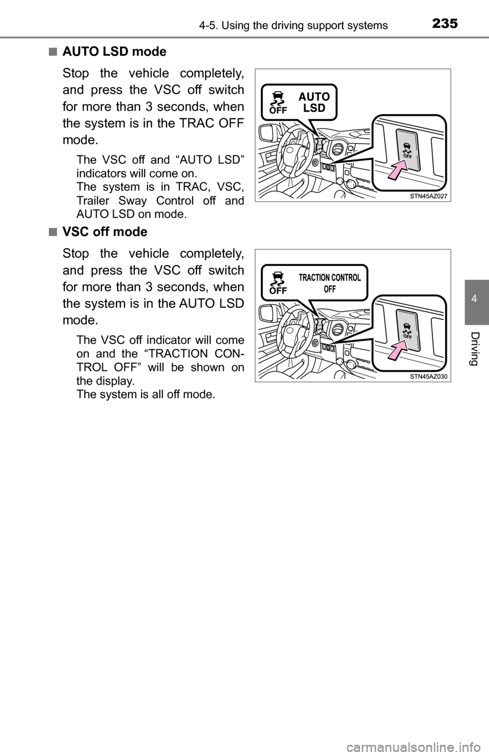
■AUTO LSD mode
Stop the vehicle completely,
and press the VSC off switch
for more than 3 seconds, when
the system is in the TRAC OFF
mode.
The VSC off and “AUTO LSD”
indicators will come on.
The system is in TRAC, VSC,
Trailer Sway Control off and
AUTO LSD on mode.
■
VSC off mode
Stop the vehicle completely,
and press the VSC off switch
for more than 3 seconds, when
the system is in the AUTO LSD
mode.
The VSC off indicator will come
on and the “TRACTION CON-
TROL OFF” will be shown on
the display.
The system is all off mode.
Page 236 of 588
2364-5. Using the driving support systems
If the vehicle gets stuck in fresh snow or mud, VSC/Trailer Sway Con-
trol/A-TRAC systems may reduce power from the engine to the
wheels. You may need to turn the system off to enable you to rock the
vehicle in order to free it.
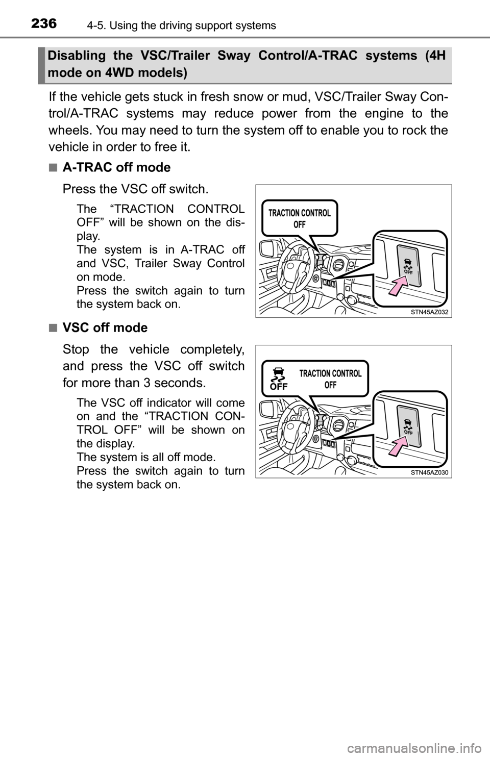
■A-TRAC off mode
Press the VSC off switch.
The “TRACTION CONTROL
OFF” will be shown on the dis-
play.
The system is in A-TRAC off
and VSC, Trailer Sway Control
on mode.
Press the switch again to turn
the system back on.
■
VSC off mode
Stop the vehicle completely,
and press the VSC off switch
for more than 3 seconds.
The VSC off indicator will come
on and the “TRACTION CON-
TROL OFF” will be shown on
the display.
The system is all off mode.
Press the switch again to turn
the system back on.
Disabling the VSC/Trailer Sway Control/A-TRAC systems (4H
mode on 4WD models)
Page 240 of 588
2404-5. Using the driving support systems
Trailer brake controller
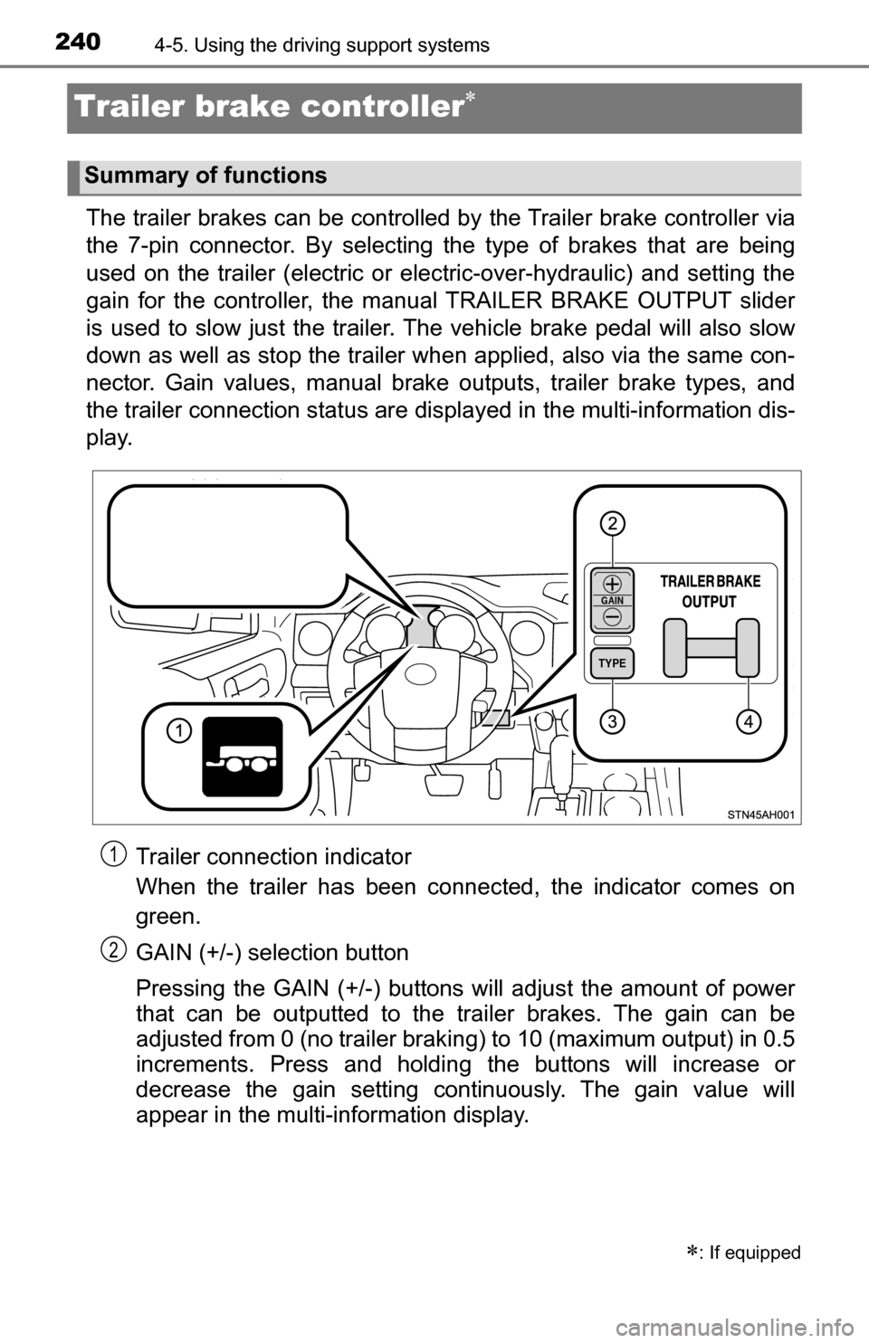
The trailer brakes can be controlled by the Trailer brake controller via
the 7-pin connector. By selecting th e type of brakes that are being
used on the trailer (electric or electric-over-hydraulic) and setting the
gain for the controller, the manual TRAILER BRAKE OUTPUT slider
is used to slow just the trailer. The vehicle brake pedal will also slow
down as well as stop the trailer when applied, also via the same con-
nector. Gain values, manual brake outputs, trailer brake types, and
the trailer connection stat us are displayed in the multi-information dis-
play.
Trailer connection indicator
When the trailer has been connected, the indicator comes on
green.
GAIN (+/-) selection button
Pressing the GAIN (+/-) buttons will adjust the amount of power
that can be outputted to the trailer brakes. The gain can be
adjusted from 0 (no trailer braki ng) to 10 (maximum output) in 0.5
increments. Press and holding the buttons will increase or
decrease the gain setting continuously. The gain value will
appear in the multi-information display.
: If equipped
Summary of functions
TYPE
GAIN
1
2
Page 241 of 588
2414-5. Using the driving support systems
4
Driving
Trailer brake TYPE selection button
Trailer brake type can be selected by pressing the trailer brake TYPE
selection button on the trailer brake controller. Trailer brake TYPE selec-
tion button will cycle through electric trailer brake and electric-over-
hydraulic trailer brakes. The combination meter will show which trailer
brake type is selected in the multi-information display after pressing the
trailer brake TYPE selection button.
Manual TRAILER BRAKE OUTPUT slider
Adjusting this slider position will engage the trailer’s brakes only. If the
manual TRAILER BRAKE OUTPUT slider is used while the vehicle
brake is applied, the greater of the two outputs will be sent to the trailer
brakes.
Gain setting on trailer brake controller should be set for a specific tow-
ing condition. Gain setting should be adjusted each time the vehicle
load, trailer load, road conditions, or weather changes. Setting the
gain value to 0 will disable the trailer brake controller output.
Make sure the trailer brakes are in good working condition and
functioning normally. See trailer dealer if necessary.
Hook up the trailer and make proper electrical connections.
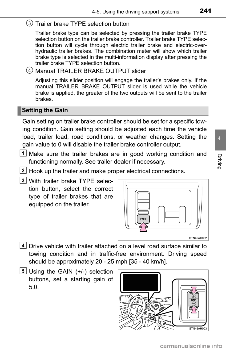
With trailer brake TYPE selec-
tion button, select the correct
type of trailer brakes that are
equipped on the trailer.
Drive vehicle with trailer attached on a level road surface similar to
towing condition and in traffic-free environment. Driving speed
should be approximately 20 - 25 mph [35 - 40 km/h].
Using the GAIN (+/-) selection
buttons, set a starting gain of
5.0.
Setting the Gain
3
4
1
2
3
4
5