display TOYOTA TUNDRA 2019 (in English) Service Manual
[x] Cancel search | Manufacturer: TOYOTA, Model Year: 2019, Model line: TUNDRA, Model: TOYOTA TUNDRA 2019Pages: 672, PDF Size: 14.1 MB
Page 269 of 672
2694-5. Using the driving support systems
4
Driving
Intuitive parking assist
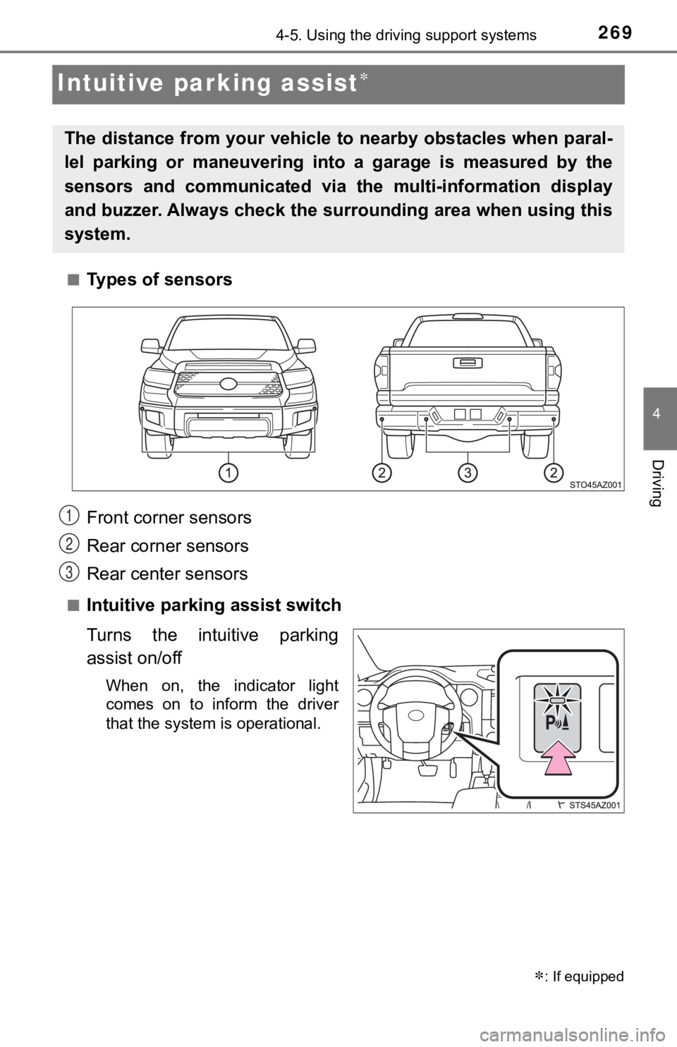
■Types of sensors
■Intuitive parking assist switch
Turns the intuitive parking
assist on/off
When on, the indicator light
comes on to inform the driver
that the system is operational.
: If equipped
The distance from your vehicle to nearby obstacles when paral-
lel parking or maneuvering into a garage is measured by the
sensors and communicated via the multi-information display
and buzzer. Always check the surrounding area when using this
system.
Front corner sensors
Rear corner sensors
Rear center sensors1
2
3
Page 270 of 672
2704-5. Using the driving support systems
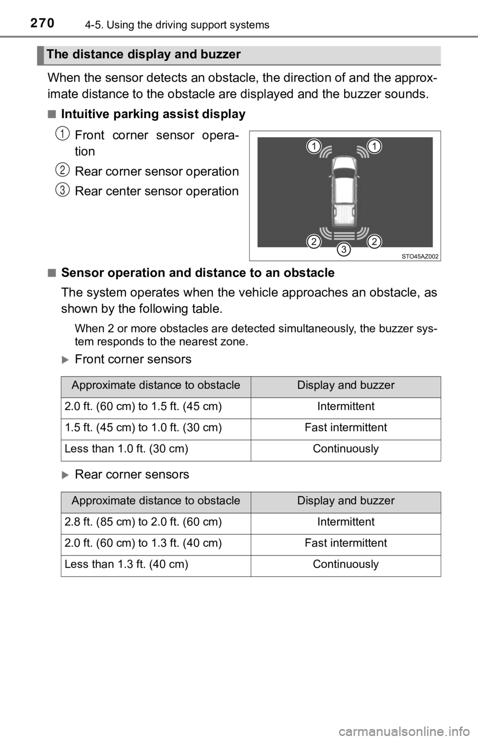
When the sensor detects an obstacle, the direction of and the a pprox-
imate distance to the o bstacle are displayed and the buzzer sou nds.
■Intuitive parking assist display
Front corner sensor opera-
tion
Rear corner sensor operation
Rear center sensor operation
■Sensor operation and di stance to an obstacle
The system operates when the vehi cle approaches an obstacle, as
shown by the following table.
When 2 or more obstacles are detected simultaneously, the buzze r sys-
tem responds to the nearest zone.
Front corner sensors
Rear corner sensors
The distance display and buzzer
1
2
3
Approximate distance to obstacleDisplay and buzzer
2.0 ft. (60 cm) to 1.5 ft. (45 cm)Intermittent
1.5 ft. (45 cm) to 1.0 ft. (30 cm)Fast intermittent
Less than 1.0 ft. (30 cm)Continuously
Approximate distance to obstacleDisplay and buzzer
2.8 ft. (85 cm) to 2.0 ft. (60 cm)Intermittent
2.0 ft. (60 cm) to 1.3 ft. (40 cm)Fast intermittent
Less than 1.3 ft. (40 cm)Continuously
Page 271 of 672
2714-5. Using the driving support systems
4
Driving
Rear center sensor
■When multiple obstacles are detected in front and behind the
vehicle at the same time
The buzzer will change in the following manner.
● If an obstacle has been detected within 1.5 ft. (45 cm) of the front
or 2.8 ft. (85 cm) in rear of t he vehicle (a continuous buzzer is
sounding), and a new obstacle is detected at the other end of the
vehicle, the buzzer w ill sound 7 times then 1 continuous buzzer.
● If an obstacle has been detected within 1.5 ft. (45 cm) of the front
or 2.8 ft. (85 cm) in rear of t he vehicle (a continuous buzzer is
sounding), and a new obstacle is detected in the same way at th e
other end of the vehicle, the buzzer will sound 3 times then 1
continuous buzzer.
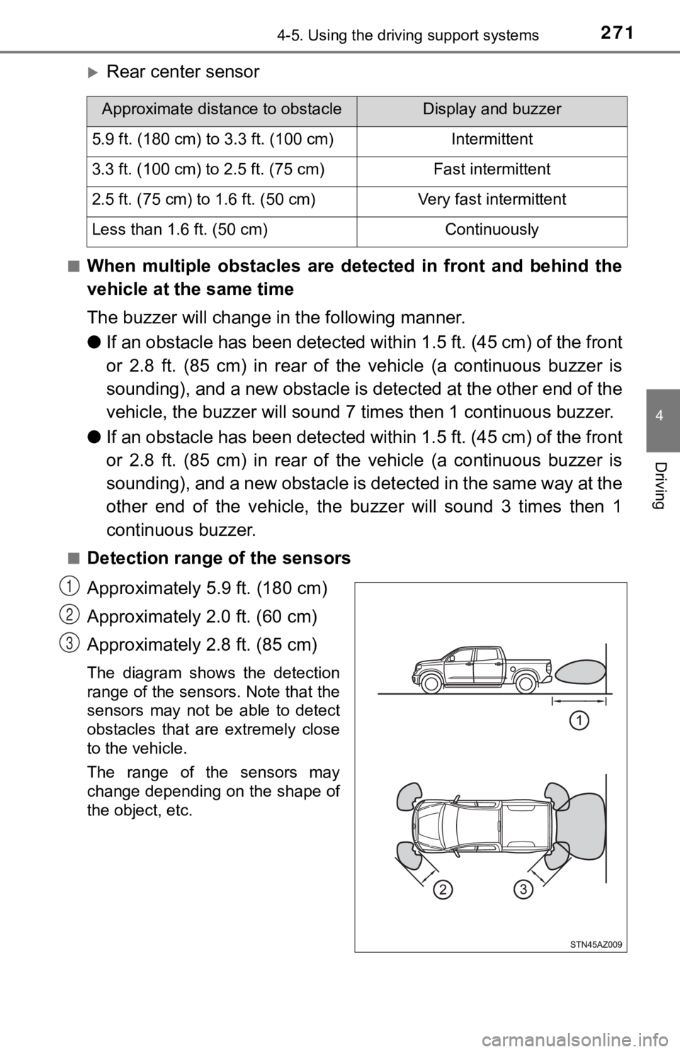
■Detection range of the sensors
Approximately 5.9 ft. (180 cm)
Approximately 2.0 ft. (60 cm)
Approximately 2.8 ft. (85 cm)
The diagram shows the detection
range of the sensors. Note that the
sensors may not be able to detect
obstacles that are extremely close
to the vehicle.
The range of the sensors may
change depending on the shape of
the object, etc.
Approximate distance to obstacleDisplay and buzzer
5.9 ft. (180 cm) to 3.3 ft. (100 cm)Intermittent
3.3 ft. (100 cm) to 2.5 ft. (75 cm)Fast intermittent
2.5 ft. (75 cm) to 1.6 ft. (50 cm)Very fast intermittent
Less than 1.6 ft. (50 cm)Continuously
1
2
3
Page 272 of 672
2724-5. Using the driving support systems
■The intuitive parking assist can be operated when
●Front corner sensors:
• The engine switch is in the “ON” position.
• The shift lever is in R.
• The shift lever is not in P or R and vehicle speed is less than about 6 mph
(10 km/h).
● Rear corner and rear center sensors:
• The engine switch is in the “ON” position.
• The shift lever is in R.
■ If the display flashes and a message is displayed
P. 557, 558
■ Certification (Canada only)
This ISM device complies with Canadian ICES-001.
WARNING
■When using the intuitive parking assist
Observe the following precautions.
Failure to do so may result in the vehicle being unable to be driven safely
and possibly cause an accident.
● Do not use the sensor at speeds in excess of 6 mph (10 km/h).
● The sensors’ detection areas and reaction times are limited. When moving
forward or reversing, check the areas surrounding the vehicle ( especially
the sides of the vehicle) for safety, and drive slowly, using t he brake to
control the vehicle’s speed.
● Do not install accessories within the sensors’ detection areas.
Page 274 of 672

2744-5. Using the driving support systems
WARNING
●The shape of the obstacle may prevent the sensor from detecting it. Pay
particular attention to the following obstacles:
• Wires, fences, ropes, etc.
• Cotton, snow and other materials that absorb sound waves
• Sharply-angled objects
• Low obstacles
• Tall obstacles with upper sections projecting outwards in the direction of
your vehicle
● The following situations may occur during use.
• Depending on the shape of the obstacle and other factors, the detection
distance may shorten, or detection may be impossible.
• Obstacles may not be detected if they are too close to the sen sor.
• There will be a short delay between obstacle detection and dis play.
Even at slow speeds, there is a possibility that the obstacle w ill come
within the sensor’s detection areas before the display is shown and the
warning beep sounds.
• Thin posts or objects lower than the sensor may not be detecte d for col-
lision when approached, even if they have been detected once.
• It might be difficult to hear beeps due to the volume of audio system or
air flow noise of air conditioning system.
Page 275 of 672
2754-5. Using the driving support systems
4
Driving
NOTICE
■When using intuitive parking assist-sensor
In the following situations, the system may not function correctly due to a
sensor malfunction, etc. Have the vehicle checked by your Toyot a dealer.
● A beep does not sound when you turn the main switch on.
● The intuitive parking assist operation display flashes, and a beep sounds
when no obstacles are detected.
● If the area around a sensor collides with something, or is subjected to
strong impact.
● If the bumper collides with something.
● If the display shows continuously without a beep.
● If a display error occurs, first check the sensor.
If the error occurs even if there is no ice, snow or mud on the sensor, it is
likely that the sensor is malfunctioning.
■ Notes when washing the vehicle
Do not apply intensive bursts of water or steam to the sensor a rea.
Doing so may result in the sensor malfunctioning.
Page 276 of 672

2764-5. Using the driving support systems
Rear view monitor system
Vehicles with Entune Audio P lus or Entune Premium Audio
(Multimedia system types: P. 322)
Refer to the “NAVIGATION AND MULTIMEDIA SYSTEM
OWNER’S MANUAL”.
Vehicles with Entune Audio ( Multimedia system types: P. 322)
The rear view image is displayed
when the shift lever is in R and the
engine switch is in the “ON” posi-
tion.
The rear view monitor system will
be deactivated when the shift lever
is in any position other than R.
The rear view monitor system ass ists the driver by displaying an
image of the view behind the vehicle with fixed guide lines on
the screen while backing up, for example while parking.
The screen illustrations used in this text are intended as exam ples,
and may differ from the image th at is actually displayed on the
screen.
Page 277 of 672
2774-5. Using the driving support systems
4
Driving
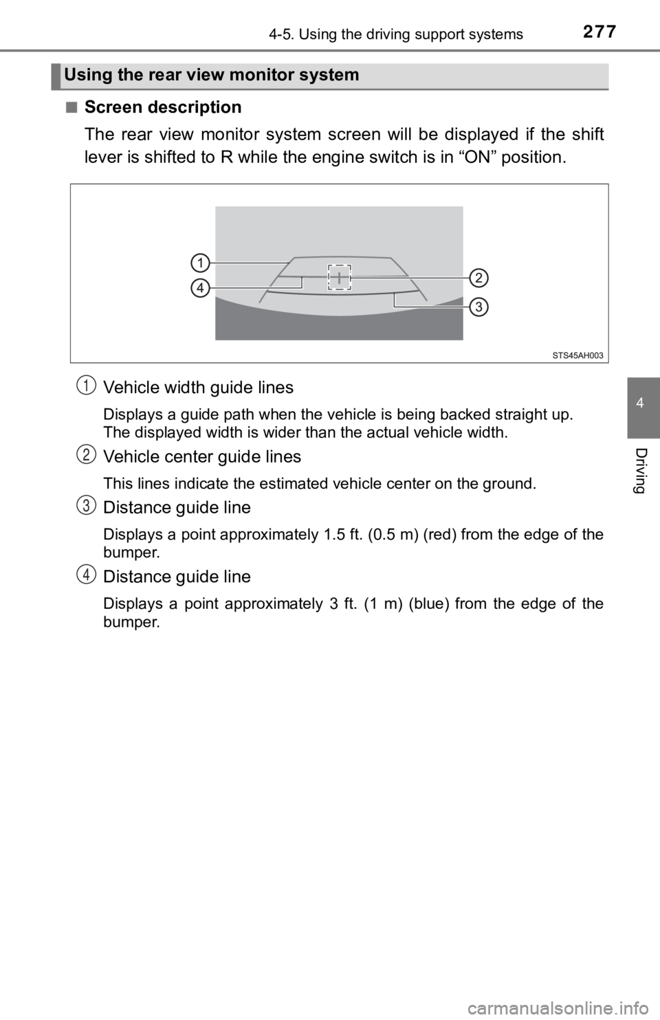
■Screen description
The rear view monitor system screen will be displayed if the sh ift
lever is shifted to R while the engine switch is in “ON” positi on.
Vehicle width guide lines
Displays a guide path when the vehicle is being backed straight up.
The displayed width is wider than the actual vehicle width.
Vehicle center guide lines
This lines indicate the estimated vehicle center on the ground.
Distance guide line
Displays a point approximately 1.5 ft. (0.5 m) (red) from the e dge of the
bumper.
Distance guide line
Displays a point approximately 3 ft. (1 m) (blue) from the edge of the
bumper.
Using the rear view monitor system
1
2
3
4
Page 278 of 672
2784-5. Using the driving support systems
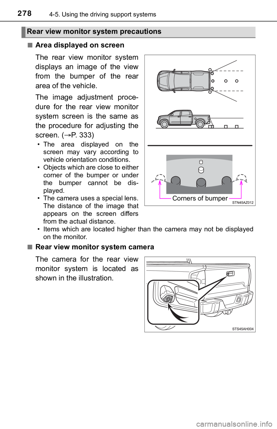
■Area displayed on screen
The rear view monitor system
displays an image of the view
from the bumper of the rear
area of the vehicle.
The image adjustment proce-
dure for the rear view monitor
system screen is the same as
the procedure for adjusting the
screen. (P. 3 3 3 )
• The area displayed on the
screen may vary according to
vehicle orientation conditions.
• Objects which are close to either corner of the bumper or under
the bumper cannot be dis-
played.
• The camera uses a special lens. The distance of the image that
appears on the screen differs
from the actual distance.
• Items which are located higher than the camera may not be disp layed
on the monitor.
■
Rear view monitor system camera
The camera for the rear view
monitor system is located as
shown in the illustration.
Rear view monitor system precautions
Corners of bumper
Page 280 of 672
2804-5. Using the driving support systems
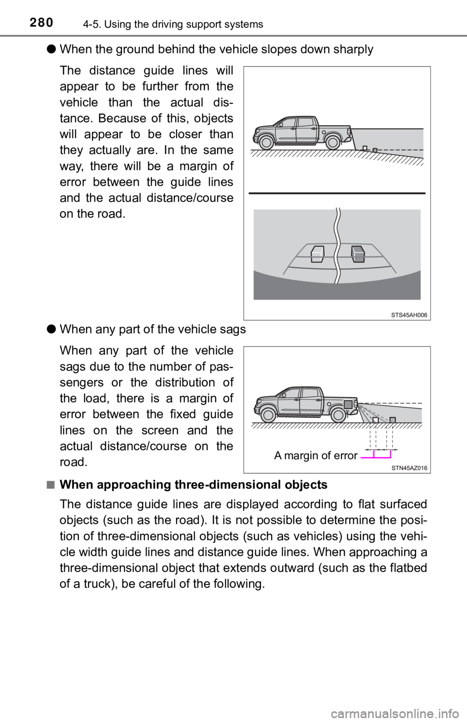
●When the ground behind the ve hicle slopes down sharply
The distance guide lines will
appear to be further from the
vehicle than the actual dis-
tance. Because of this, objects
will appear to be closer than
they actually are. In the same
way, there will be a margin of
error between the guide lines
and the actual distance/course
on the road.
● When any part of the vehicle sags
When any part of the vehicle
sags due to the number of pas-
sengers or the distribution of
the load, there is a margin of
error between the fixed guide
lines on the screen and the
actual distance/course on the
road.
■When approaching thre e-dimensional objects
The distance guide lines are displayed according to flat surfac ed
objects (such as the road). It i s not possible to determine the posi-
tion of three-dimensional object s (such as vehicles) using the vehi-
cle width guide lines and distance guide lines. When approachin g a
three-dimensional object that ext ends outward (such as the flatbed
of a truck), be careful of the following.
A margin of error