Info center TOYOTA TUNDRA 2021 Owners Manual (in English)
[x] Cancel search | Manufacturer: TOYOTA, Model Year: 2021, Model line: TUNDRA, Model: TOYOTA TUNDRA 2021Pages: 612, PDF Size: 13.7 MB
Page 81 of 612
811-2. Emergency assistance
1
For safety and security
■Safety Connect Services Information
●Phone calls using the vehicle’s Bluetooth® technology will not be possible
when Safety Connect is active and in use.
● Safety Connect is available beginning Fall 2009 on select Toyot a models (in
the contiguous United States only). Contact with the Safety Con nect
response center is dependent upon the telematics device being i n operative
condition, cellular connection availability, and GPS satellite signal reception,
which can limit the ability to reach the response center or rec eive emer-
gency service support. Enrollment and Telematics Subscription S ervice
Agreement are required. A variety of subscription terms are ava ilable;
charges vary by subscription term selected and location.
● Automatic Collision Notification, Emergency Assistance and Stolen Vehicle
Location are available in the United States, including Hawaii a nd Alaska,
Puerto Rico and Canada, and Enhanced Roadside Assistance are av ailable
in the United States, Puerto Rico and Canada.
● Automatic Collision Notification, Emergency Assistance, Stolen Vehicle and
Enhanced Road Assistance are not available in the U.S. Virgin Islands. For
vehicles first sold in the U.S. Virgin Islands, no Safety Conne ct services will
function in or outside the U.S. Virgin Islands.
● Safety Connect services are not subject to section 255 of the T elecommuni-
cations Act and the device is not TTY compatible.
■ Languages
The Safety Connect response center will offer support in multip le languages.
The Safety Connect system will offer voice prompts in English, Spanish, and
French. Please indicate your language of choice when enrolling.
■ When contacting the response center
You may be unable to contact the response center if the network is busy.
When the engine switch is turned to ON, the red indicator light comes
on for 2 seconds then turns off. Afterward, the green indicator light
comes on, indicating that the service is active.
The following indicator light patterns indicate specific system usage
conditions:
● Green indicator light on = Active service
● Green indicator light flashing = Safety Connect call in process
● Red indicator light (except at vehicle start-up) = System malfunction
(contact your Toyota dealer)
● No indicator light (off) = Saf ety Connect service not active
Safety Connect LED light Indicators
Page 82 of 612
821-2. Emergency assistance
■Automatic Collision Notification
In case of either airbag deployment or severe rear-end collision, the
system is designed to automatically call the response center. T he
responding agent receives the v ehicle’s location and attempts to
speak with the vehicl e occupants to assess the level of emergency.
If the occupants are unable to communicate, the agent automati-
cally treats the call as an emergency, contacts the nearest eme r-
gency services provider to descr ibe the situation, and requests that
assistance be sent to the location.
■Stolen Vehicle Location
If your vehicle is stolen, Safety Connect can work with local author-
ities to assist them in locating and recovering the vehicle. Af ter filing
a police report, call the Customer Experience Center at 1-800-3 31-
4331 in the United States, 1-877-8 55-8377 in Puerto Rico or 1-888-
869-6828 in Canada, and follow the prompts for Safety Connect t o
initiate this service.
In addition to assisting law enforcement with recovery of a sto len
vehicle, Safety-Connect-equipped vehicle location data may, und er
certain circumstances, be shared with third parties to locate y our
vehicle. Further information is a vailable at Toyota.com in the United
States, Toyotapr.com in Puerto Rico and Toyota.ca in Canada.
■Emergency Assistance Button (“SOS”)
In the event of an emergency on t he road, push the “SOS” button to
reach the Safety Connect respons e center. The answering agent
will determine your vehicle’s loca tion, assess the emergency, and
dispatch the necessary assistanc e required.
If you accidentally press the “SOS” button, tell the response-c enter
agent that you are not experiencing an emergency.
Safety Connect LED light Indicators
Page 83 of 612
831-2. Emergency assistance
1
For safety and security
■Enhanced Roadside Assistance
Enhanced Roadside Assistance adds GPS data to the already
included warranty-based Toyota roadside service.
Subscribers can press the “SOS” button to reach a Safety Connec t
response-center agent, who can he lp with a wide range of needs,
such as: towing, flat tire, fuel delivery, etc. For a description of the
Enhanced Roadside Assistance se rvices and their limitations,
please see the Safety Connect Te rms and Conditions, which are
available at Toyota.com in the United States, Toyotapr.com in
Puerto Rico and Toyota.ca in Canada.
Important! Read this informatio n before using Safety Connect.
■Exposure to radio frequency signals
The Safety Connect system installed in your vehicle is a low-po wer
radio transmitter and receiver. I t receives and also sends out radio
frequency (RF) signals.
In August 1996, the Federal Communications Commission (FCC)
adopted RF exposure guidelines with safety levels for mobile wi re-
less phones. Those guidelines are consistent with the safety stan-
dards previously set by the following U.S. and international
standards bodies.
● ANSI (American National Stand ards Institute) C95.1 [1992]
● NCRP (National Council on Radi ation Protection and Measure-
ment) Report 86 [1986]
● ICNIRP (International Commission on Non-Ionizing Radiation
Protection) [1996]
Those standards were based on comprehensive and periodic eval-
uations of the relevant scienti fic literature. Over 120 scientists, engi-
neers, and physicians from unive rsities, and government health
agencies and industries reviewed the available body of research to
develop the ANSI Standard (C95.1).
The design of Safety Connect complies with the FCC guidelines i n
addition to those standards.
Safety information for Safety Connect
Page 100 of 612
1002. Instrument cluster
Warning lights and indicators
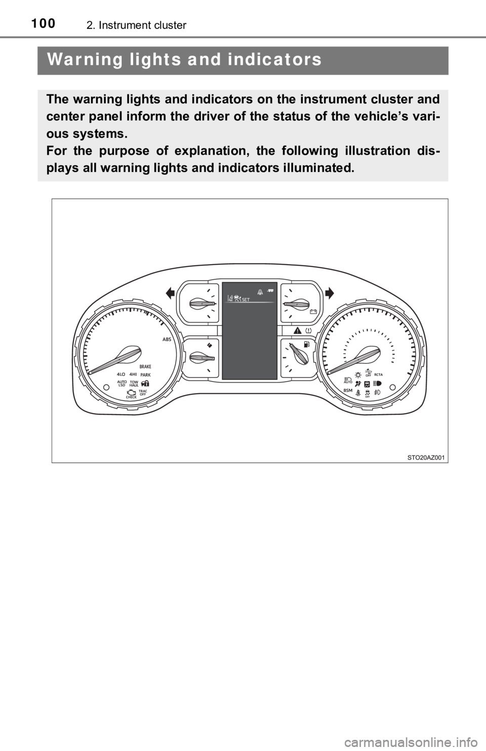
The warning lights and indicators on the instrument cluster and
center panel inform the driver of the status of the vehicle’s vari-
ous systems.
For the purpose of explanation, t he following illustration dis-
plays all warning lights a nd indicators illuminated.
Page 104 of 612
1042. Instrument cluster
*1: These lights turn on when the engine switch is turned to ON to indicate thata system check is being performed. They will turn off after the engine is
started, or after a few seconds. There may be a malfunction in a system if
the lights do not come on, or if the lights do not turn off. Ha ve the vehicle
inspected by your Toyota dealer for details.
*2: The light flashes to indicate that the system is operating.
*3: In order to confirm operation, the BSM outside rear view mirro r indicators
illuminate in the following situations:
• When the engine switch is turned to ON, the BSM function is enabled on
the screen of the multi-information display.
• When the BSM function is enabled on the screen of the multi-i nfor-
mation display, the engine switch is turned to ON.
If the system is functioning correctly, the BSM outside rear vi ew mirror indi-
cators will turn off after a few seconds.
If the BSM outside rear view mirror indicators do not illuminat e or do not
turn off, there may be a malfunction with the system.
If this occurs, have the vehicle inspected by your Toyota deale r.
*4: The light illuminates on the outside rear view mirrors.
*5: The light illuminates on the center panel.
*6: The light illuminates on the multi-information display.
*7: When the outside temperature is approximately 37°F (3°C) or lo wer, the
indicator will flash for 10 times, then comes on.
*8: The light comes on when the system is turned off.
*9: If equipped
WARNING
■ If a safety system warning light does not come on
Should a safety system light such as the ABS and SRS warning li ght not
come on when you start the engine, this could mean that these s ystems are
not available to help protect you in an accident, which could r esult in death
or serious injury. Have the vehicle inspected by your Toyota de aler immedi-
ately if this occurs.
Page 272 of 612
2724-5. Using the driving support systems
LDA (Lane Depar ture Alert)
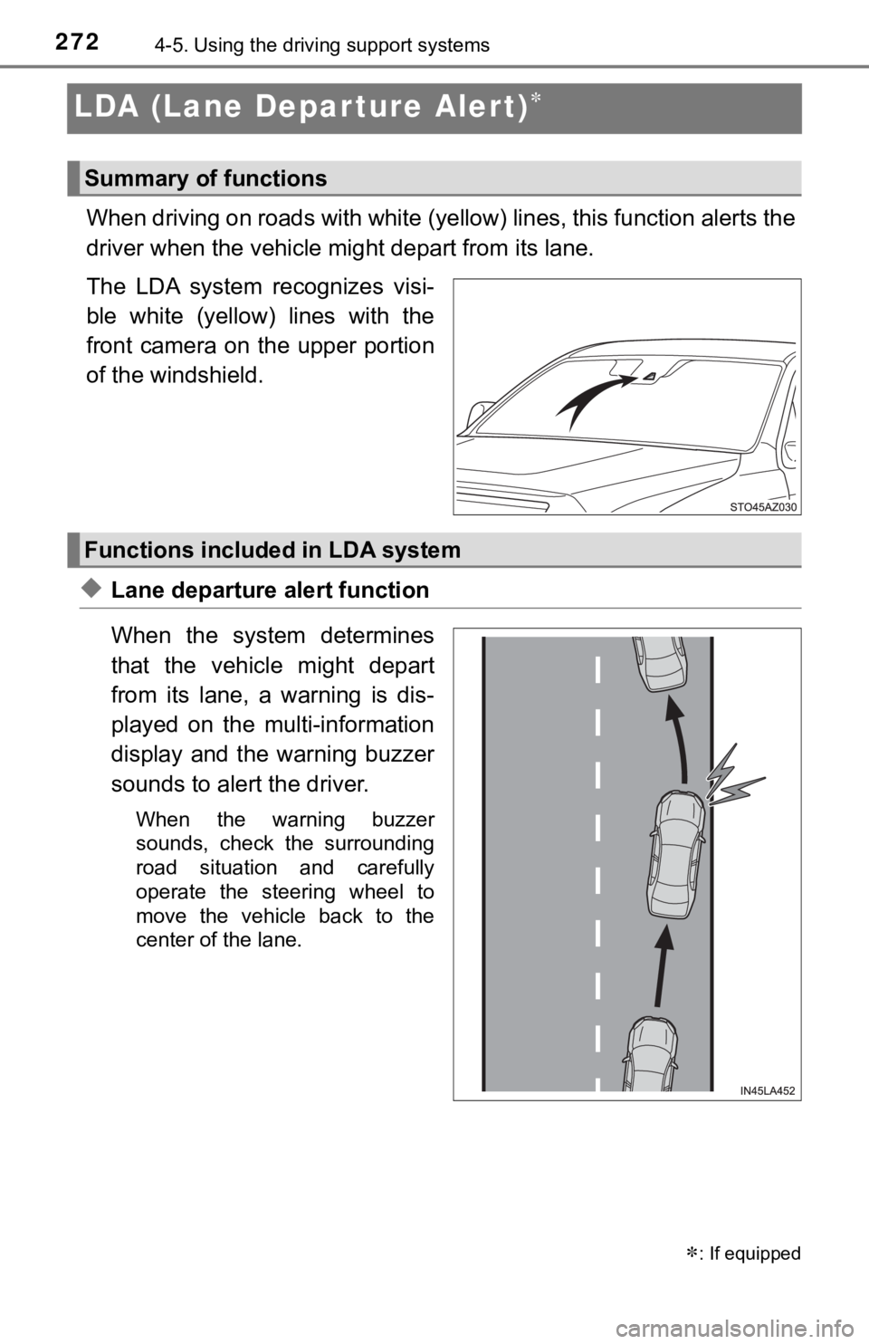
When driving on roads with white (yellow) lines, this function alerts the
driver when the vehicle mi ght depart from its lane.
The LDA system recognizes visi-
ble white (yellow) lines with the
front camera on the upper portion
of the windshield.
◆Lane departure alert function
When the system determines
that the vehicle might depart
from its lane, a warning is dis-
played on the multi-information
display and the warning buzzer
sounds to alert the driver.
When the warning buzzer
sounds, check the surrounding
road situation and carefully
operate the steering wheel to
move the vehicle back to the
center of the lane.
: If equipped
Summary of functions
Functions included in LDA system
Page 298 of 612
2984-5. Using the driving support systems
Intuitive parking assist
■Types of sensors
■Intuitive parking assist switch
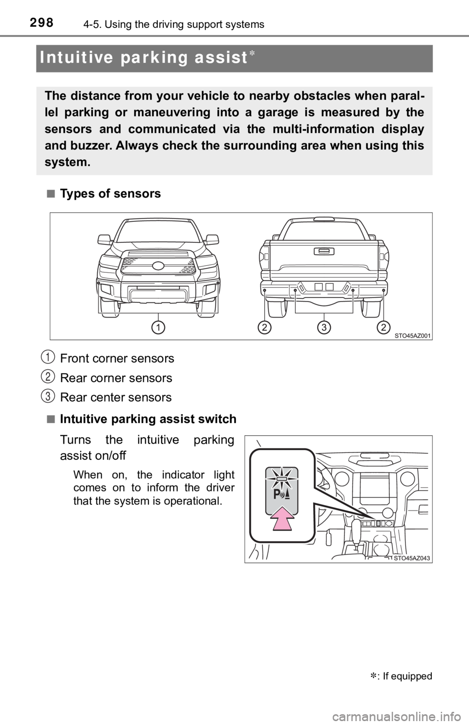
Turns the intuitive parking
assist on/off
When on, the indicator light
comes on to inform the driver
that the system is operational.
: If equipped
The distance from your vehicle to nearby obstacles when paral-
lel parking or maneuvering into a garage is measured by the
sensors and communicated via t he multi-information display
and buzzer. Always check the surrounding area when using this
system.
Front corner sensors
Rear corner sensors
Rear center sensors1
2
3
Page 560 of 612
5608-1. Specifications
Rim
A metal support for a tire or a tire and tube
assembly upon which the tire beads are
seated
Rim diameter
(Wheel diameter)Nominal diameter of the bead seat
Rim size designationRim diameter and width
Rim type designationThe industry manufacturer’s designation for a
rim by style or code
Rim widthNominal distance between rim flanges
Vehicle capacity
weight (Total load
capacity)The rated cargo and l uggage load plus 150 lb.
(68 kg) times the vehicle’s designated seating
capacity
Vehicle maximum load
on the tire
The load on an individual tire that is deter-
mined by distributing to each axle its share of
the maximum loaded vehicle weight, and
dividing by two
Vehicle normal load on
the tire
The load on an individual tire that is deter-
mined by distributing to each axle its share of
curb weight, accessory weight, and normal
occupant weight (distributed in accordance
with Table 1
* below), and dividing by two
Weather sideThe surface area of the rim not covered by the
inflated tire
Bead
The part of the tire that is made of steel wires,
wrapped or reinforced by ply cords and that is
shaped to fit the rim
Bead separationA breakdown of the bond between compo-
nents in the bead
Bias ply tire
A pneumatic tire in which the ply cords that
extend to the beads are laid at alternate
angles substantially less than 90 degrees to
the centerline of the tread
CarcassThe tire structure, except tread and sidewall
rubber which, when inflated, bears the load
ChunkingThe breaking away of pieces of the tread or
sidewall
CordThe strands forming th e plies in the tire
Tire related termMeaning
Page 562 of 612
5628-1. Specifications
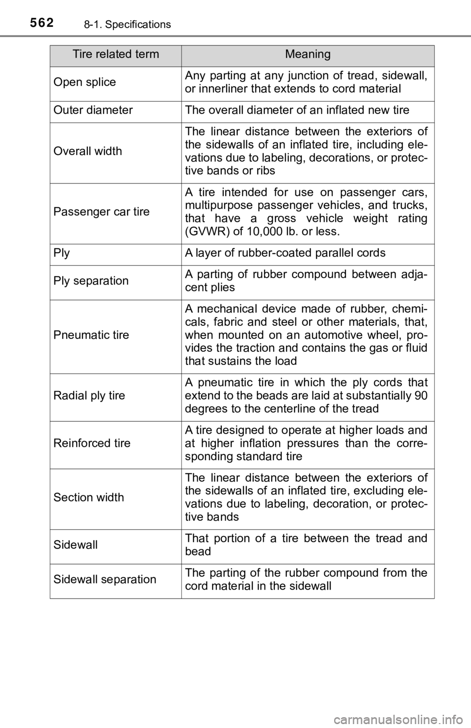
Open spliceAny parting at any junction of tread, sidewall,
or innerliner that extends to cord material
Outer diameterThe overall diameter of an inflated new tire
Overall width
The linear distance between the exteriors of
the sidewalls of an inflated tire, including ele-
vations due to labeling, decorations, or protec-
tive bands or ribs
Passenger car tire
A tire intended for use on passenger cars,
multipurpose passenger vehicles, and trucks,
that have a gross vehicle weight rating
(GVWR) of 10,000 lb. or less.
PlyA layer of rubber-coated parallel cords
Ply separationA parting of rubber compound between adja-
cent plies
Pneumatic tire
A mechanical device made of rubber, chemi-
cals, fabric and steel or other materials, that,
when mounted on an automotive wheel, pro-
vides the traction and co ntains the gas or fluid
that sustains the load
Radial ply tire
A pneumatic tire in which the ply cords that
extend to the beads are laid at substantially 90
degrees to the centerline of the tread
Reinforced tire
A tire designed to operate at higher loads and
at higher inflation pressures than the corre-
sponding standard tire
Section width
The linear distance between the exteriors of
the sidewalls of an inflated tire, excluding ele-
vations due to labeling, decoration, or protec-
tive bands
SidewallThat portion of a tire between the tread and
bead
Sidewall separationThe parting of the rubber compound from the
cord material in the sidewall
Tire related termMeaning
Page 588 of 612
588
Camper information
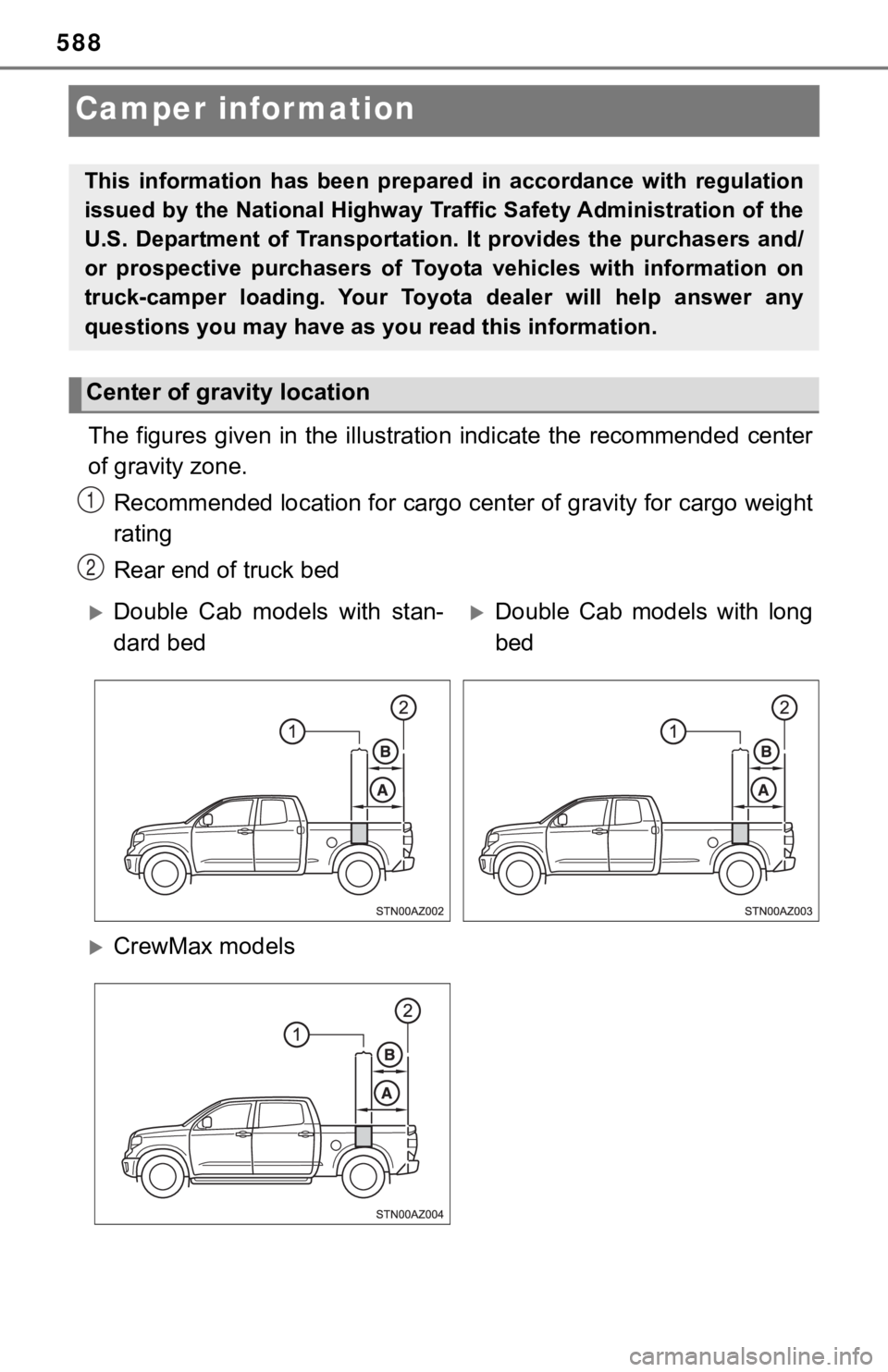
The figures given in the illustration indicate the recommended center
of gravity zone.
Recommended location for cargo center of gravity for cargo weig ht
rating
Rear end of truck bed
This information has been prepared in accordance with regulatio n
issued by the National Highway Traffic Safety Administration of the
U.S. Department of Transportation. It provides the purchasers a nd/
or prospective purchasers of Toyota vehicles with information o n
truck-camper loading. Your Toyota dealer will help answer any
questions you may have as you read this information.
Center of gravity location
1
2
Double Cab models with stan-
dard bedDouble Cab models with long
bed
CrewMax models