ESP TOYOTA TUNDRA HYBRID 2022 Owner's Guide
[x] Cancel search | Manufacturer: TOYOTA, Model Year: 2022, Model line: TUNDRA HYBRID, Model: TOYOTA TUNDRA HYBRID 2022Pages: 618, PDF Size: 19.91 MB
Page 256 of 618
2564-5. Using the driving support systems
Owners Manual_USA_M0C031_en
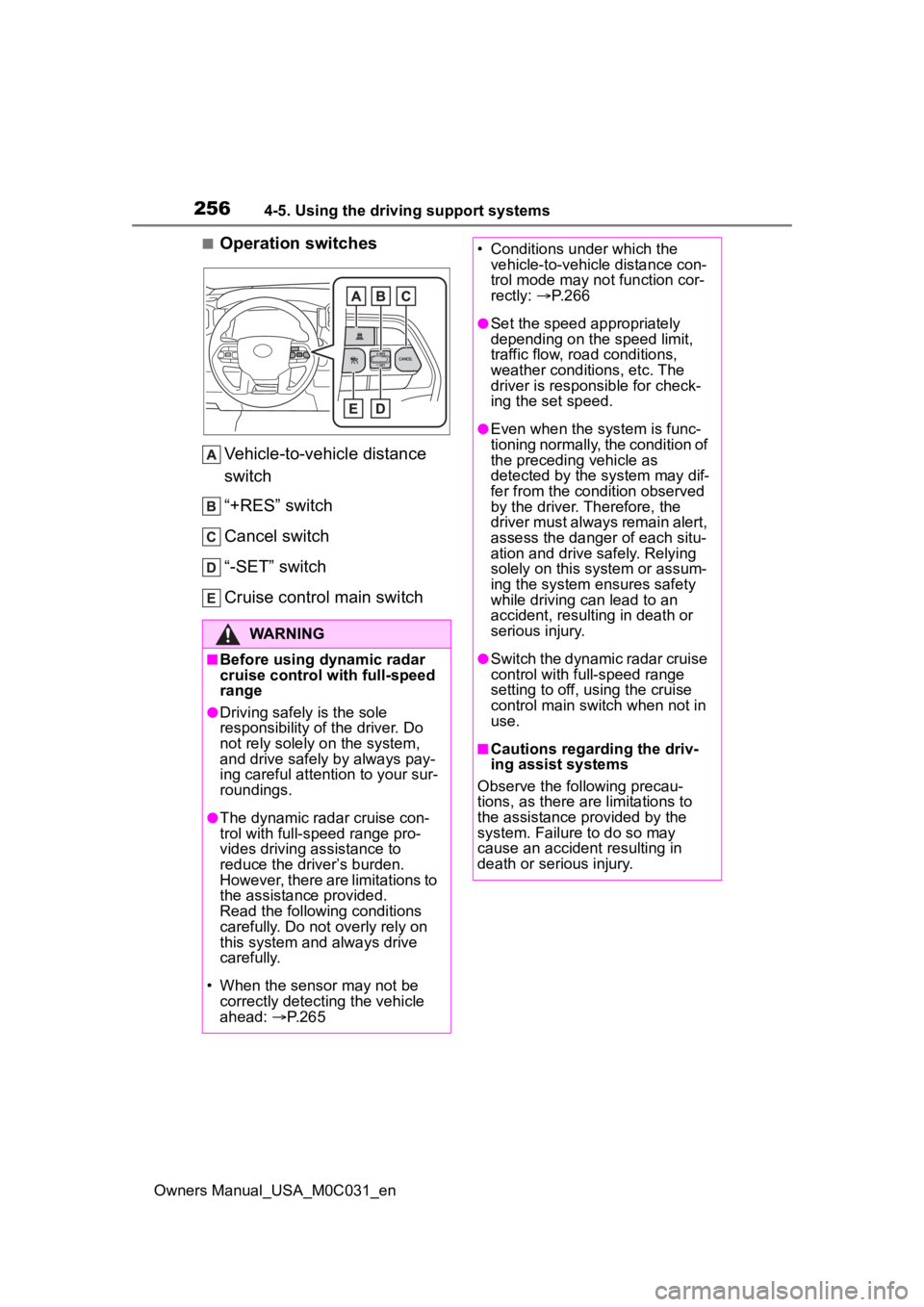
■Operation switchesVehicle-to-vehicle distance
switch
“+RES” switch
Cancel switch
“-SET” switch
Cruise control main switch
WARNING
■Before using dynamic radar
cruise control with full-speed
range
●Driving safely is the sole
responsibility of the driver. Do
not rely solely o n the system,
and drive safely by always pay-
ing careful attention to your sur-
roundings.
●The dynamic radar cruise con-
trol with full-speed range pro-
vides driving assistance to
reduce the driver’s burden.
However, there are limitations to
the assistance provided.
Read the following conditions
carefully. Do not overly rely on
this system and always drive
carefully.
• When the sensor may not be correctly detect ing the vehicle
ahead: P. 2 6 5
• Conditions under which the
vehicle-to-vehicle distance con-
trol mode may not function cor-
rectly: P. 2 6 6
●Set the speed appropriately
depending on the speed limit,
traffic flow, road conditions,
weather conditions, etc. The
driver is responsible for check-
ing the set speed.
●Even when the system is func-
tioning normally, the condition of
the preceding vehicle as
detected by the system may dif-
fer from the condition observed
by the driver. Therefore, the
driver must always remain alert,
assess the danger of each situ-
ation and drive safely. Relying
solely on this system or assum-
ing the system ensures safety
while driving can lead to an
accident, resulting in death or
serious injury.
●Switch the dynamic radar cruise
control with full-speed range
setting to off, using the cruise
control main switch when not in
use.
■Cautions regarding the driv-
ing assist systems
Observe the following precau-
tions, as there ar e limitations to
the assistance provided by the
system. Failure to do so may
cause an accident resulting in
death or serious injury.
Page 259 of 618
2594-5. Using the driving support systems
Owners Manual_USA_M0C031_en
4
Driving
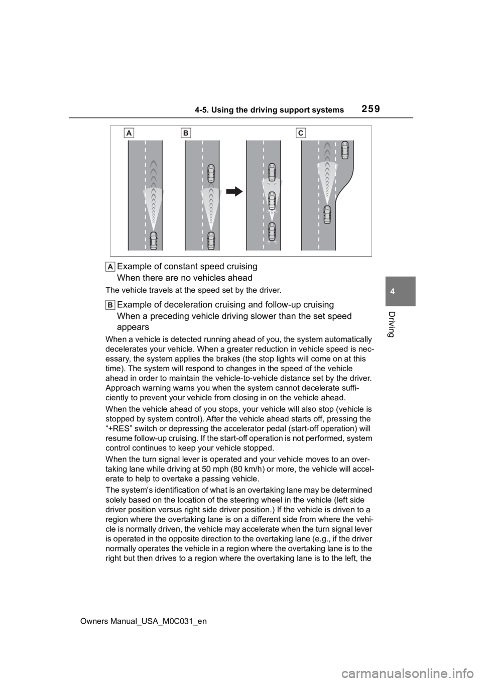
Example of constant speed cruising
When there are no vehicles ahead
The vehicle travels at the speed set by the driver.
Example of deceleration crui sing and follow-up cruising
When a preceding vehicle driving slower than the set speed
appears
When a vehicle is detected runni ng ahead of you, the system automatically
decelerates your vehicle. When a greater reduction in vehicle s peed is nec-
essary, the system applies the brakes (the stop lights will come on at this
time). The system will respond to changes in the speed of the vehicle
ahead in order to maintain the vehicle-to-vehicle distance set by the driver.
Approach warning warns you when the system cannot decelerate suffi-
ciently to prevent your vehicle from closing in on the vehicle ahead.
When the vehicle ahead of you st ops, your vehicle will also stop (vehicle is
stopped by system control). Afte r the vehicle ahead starts off, pressing the
“+RES” switch or depressing the accelerator pedal (start-off operation) will
resume follow-up cruising. If the start-off operation is not pe rformed, system
control continues to keep your vehicle stopped.
When the turn signal lever is ope rated and your vehicle moves to an over-
taking lane while driving at 50 mph (80 km/h) or more, the vehi cle will accel-
erate to help to overt ake a passing vehicle.
The system’s identification of what is an overtaking lane may be determined
solely based on the location of the steering wheel in the vehicle (left side
driver position versus right side driver position.) If the vehi cle is driven to a
region where the overtaking lane is on a different side from wh ere the vehi-
cle is normally driven, the vehicle may accelerate when the tur n signal lever
is operated in the opposite direction to the overtaking lane (e .g., if the driver
normally operates the vehicle in a region where the overtaking lane is to the
right but then drives to a region where the overtaking lane is to the left, the
Page 262 of 618
2624-5. Using the driving support systems
Owners Manual_USA_M0C031_en
Select a distance from the table
below. Note that the distances
shown correspond to a vehicle
speed of 50 mph (80 km/h).
Vehicle-to-vehicle distance
increases/decreases in accor-
dance with vehicle speed. When
the vehicle is stopped by system
control, the vehicle stops at a
certain vehicle-to-vehicle dis-
tance depending on the situa-
tion.
After the vehicle ahead of you
starts off, press the “+RES”
switch.
Your vehicle will also resume
follow-up cruising if the acceler-ator pedal is depressed after the
vehicle ahead of you starts off.
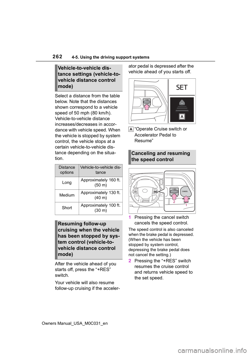
“Operate Cruise switch or
Accelerator Pedal to
Resume”
1 Pressing the cancel switch
cancels the speed control.
The speed control is also canceled
when the brake pedal is depressed.
(When the vehicle has been
stopped by system control,
depressing the br ake pedal does
not cancel the setting.)
2 Pressing the “+RES” switch
resumes the cruise control
and returns vehicle speed to
the set speed.
Vehicle-to-vehicle dis-
tance settings (vehicle-to-
vehicle distance control
mode)
Distance
optionsVehicle-to-vehicle dis- tance
LongApproximately 160 ft. (50 m)
MediumApproximately 130 ft. (40 m)
ShortApproximately 100 ft. (30 m)
Resuming follow-up
cruising when the vehicle
has been stopped by sys-
tem control (vehicle-to-
vehicle distance control
mode)
Canceling and resuming
the speed control
Page 265 of 618
2654-5. Using the driving support systems
Owners Manual_USA_M0C031_en
4
Driving
any reasons other than the above,
there may be a malfunction in the
system. Contact your Toyota dealer.
■Automatic cancelation of con-
stant speed control mode
Constant speed control mode is
automatically cance led in the follow-
ing situations:
●Actual vehicle speed is more than
approximately 10 mph (16 km/h)
below the set vehicle speed.
●Actual vehicle speed falls below
approximately 20 mph (30 km/h).
●VSC is activated.
●TRAC is activated for a period of
time.
●When the VSC or TRAC system is
turned off.
●When the brake control or output
restriction control of a driving sup-
port system operates. (For exam-
ple: Pre-Collision System, Drive-
Start Control)
●The center differential lock/unlock
is not completed within 5 seconds
while the cruise con trol system is
on.
●The parking brake is operated.
If constant speed control mode is
automatically canceled for any rea-
sons other than the above, there
may be a malfunction in the system.
Contact your Toyota dealer.
■Brake operation
A brake operation sound may be
heard and the brake pedal response
may change, but the se are not mal-
functions.
■Warning messages and buzzers
for dynamic radar cruise con-
trol with full-speed range
Warning messages and buzzers are
used to indicate a system malfunc-
tion or to inform the driver of the
need for caution while driving. If a
warning message is shown on the
multi-information display, read the
message and follow the instruc- tions.(
P.228, 511)
■When the sensor may not be
correctly detecting the vehicle
ahead
In the case of the following and
depending on the conditions, oper-
ate the brake pedal when decelera-
tion of the system is insufficient or
operate the accelerator pedal when
acceleration is required.
As the sensor may not be able to
correctly detect th ese types of vehi-
cles, the approach warning
( P.263) may not be activated.
●Vehicles that cut in suddenly
●Vehicles traveling at low speeds
●Vehicles that are not moving in the
same lane
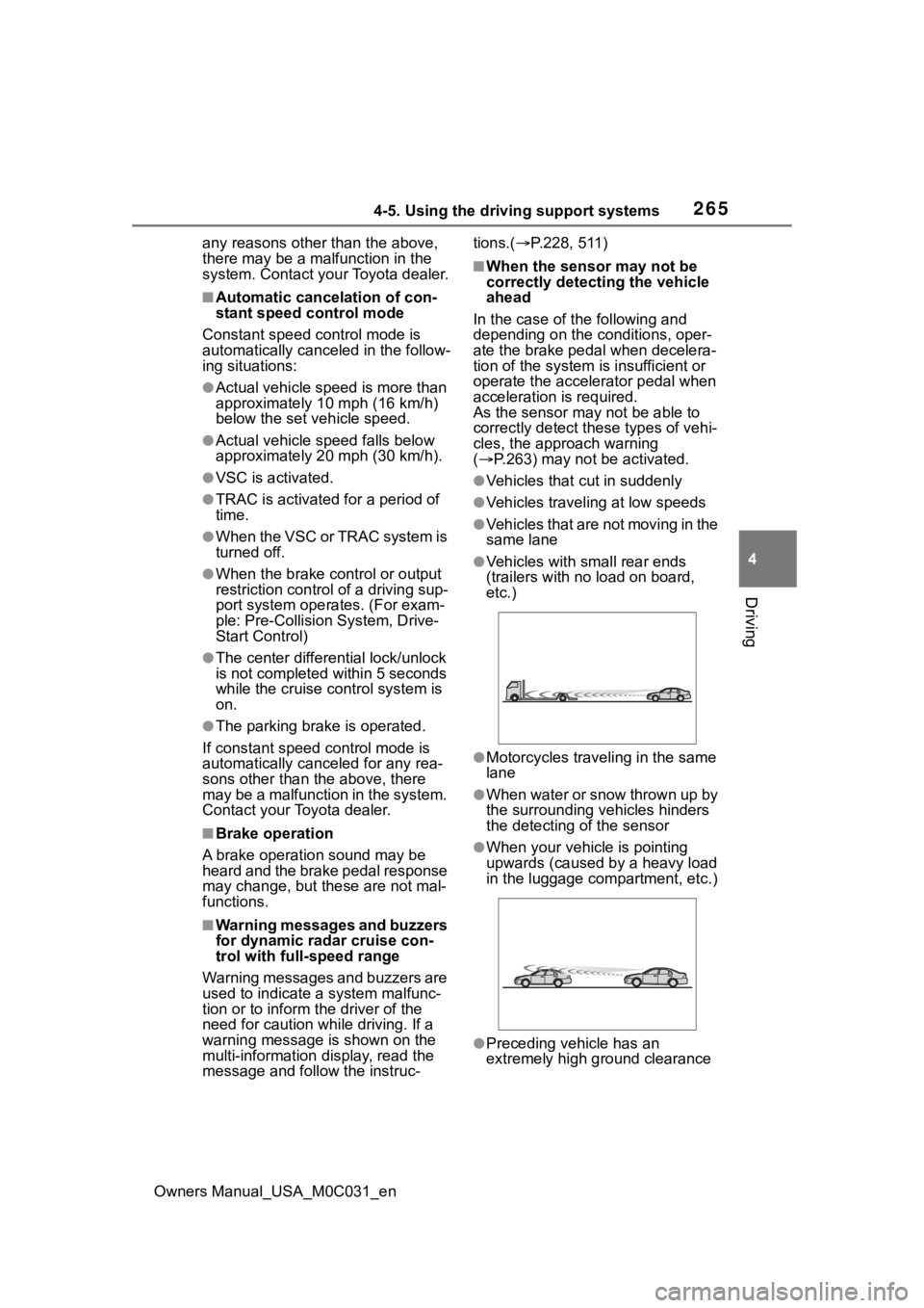
●Vehicles with small rear ends
(trailers with no load on board,
etc.)
●Motorcycles traveling in the same
lane
●When water or snow thrown up by
the surrounding vehicles hinders
the detecting of the sensor
●When your vehicle is pointing
upwards (caused by a heavy load
in the luggage compartment, etc.)
●Preceding vehicle has an
extremely high ground clearance
Page 267 of 618
2674-5. Using the driving support systems
Owners Manual_USA_M0C031_en
4
Driving
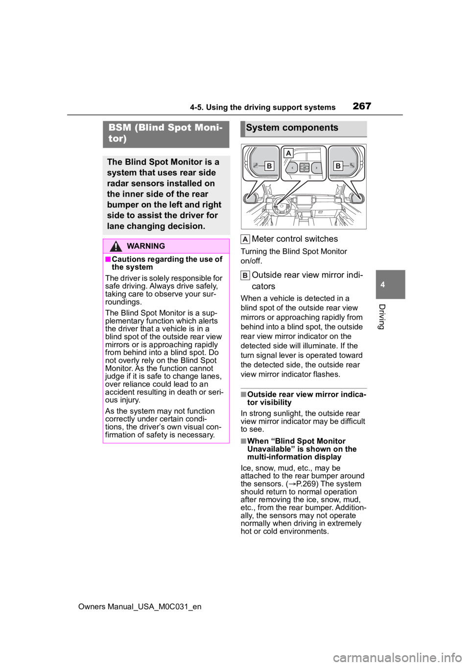
Meter control switches
Turning the Blind Spot Monitor
on/off.
Outside rear view mirror indi-
cators
When a vehicle is detected in a
blind spot of the outside rear view
mirrors or approaching rapidly from
behind into a blind spot, the outside
rear view mirror indicator on the
detected side will illuminate. If the
turn signal lever is operated toward
the detected side, the outside rear
view mirror indicator flashes.
■Outside rear vie w mirror indica-
tor visibility
In strong sunlight, the outside rear
view mirror indicator may be difficult
to see.
■When “Blind Spot Monitor
Unavailable” is shown on the
multi-information display
Ice, snow, mud, etc., may be
attached to the rear bumper around
the sensors. ( P.269) The system
should return to normal operation
after removing the ice, snow, mud,
etc., from the rear bumper. Addition-
ally, the sensors may not operate
normally when drivin g in extremely
hot or cold environments.
BSM (Blind Spot Moni-
tor)
The Blind Spot Monitor is a
system that uses rear side
radar sensors installed on
the inner side of the rear
bumper on the left and right
side to assist the driver for
lane changing decision.
WARNING
■Cautions regarding the use of
the system
The driver is solely responsible for
safe driving. Always drive safely,
taking care to o bserve your sur-
roundings.
The Blind Spot Monitor is a sup-
plementary function which alerts
the driver that a v ehicle is in a
blind spot of the outside rear view
mirrors or is approaching rapidly
from behind into a blind spot. Do
not overly rely on the Blind Spot
Monitor. As the function cannot
judge if it is safe to change lanes,
over reliance could lead to an
accident resulting in death or seri-
ous injury.
As the system may not function
correctly under certain condi-
tions, the driver’s own visual con-
firmation of safety is necessary.
System components
Page 268 of 618
2684-5. Using the driving support systems
Owners Manual_USA_M0C031_en
■When “Blind Spot Monitor Mal-
function Visit Your Dealer” is
shown on the multi-information
display
There may be a sensor malfunction
or misaligned. Have the vehicle
inspected by your Toyota dealer.
■Customization
Some functions can be customized.
( P.568)
■Certification
P. 6 1 4
WARNING
■To ensure the system can
operate properly
Blind Spot Monitor sensors are
installed behind the left and right
sides of the rear bumper respec-
tively. Observe the following to
ensure the Blind Spot Monitor can
operate correctly.
WARNING
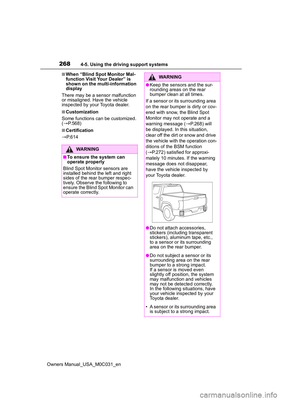
●Keep the sensors and the sur-
rounding areas on the rear
bumper clean at all times.
If a sensor or its surrounding area
on the rear bumper is dirty or cov-
ered with snow, the Blind Spot
Monitor may not operate and a
warning message ( P.268) will
be displayed. In this situation,
clear off the dirt or snow and drive
the vehicle with the operation con-
ditions of the BSM function
( P.272) satisfied for approxi-
mately 10 minutes. If the warning
message does not disappear,
have the vehicle inspected by
your Toyota dealer.
●Do not attach a ccessories,
stickers (including transparent
stickers), aluminum tape, etc.,
to a sensor or its surrounding
area on the rear bumper.
●Do not subject a sensor or its
surrounding area on the rear
bumper to a strong impact.
If a sensor is moved even
slightly off position, the system
may malfunction and vehicles
may not be detected correctly.
In the following si tuations, have
your vehicle inspected by your
Toyota dealer.
• A sensor or its surrounding area is subject to a strong impact.
Page 275 of 618
2754-5. Using the driving support systems
Owners Manual_USA_M0C031_en
4
Driving
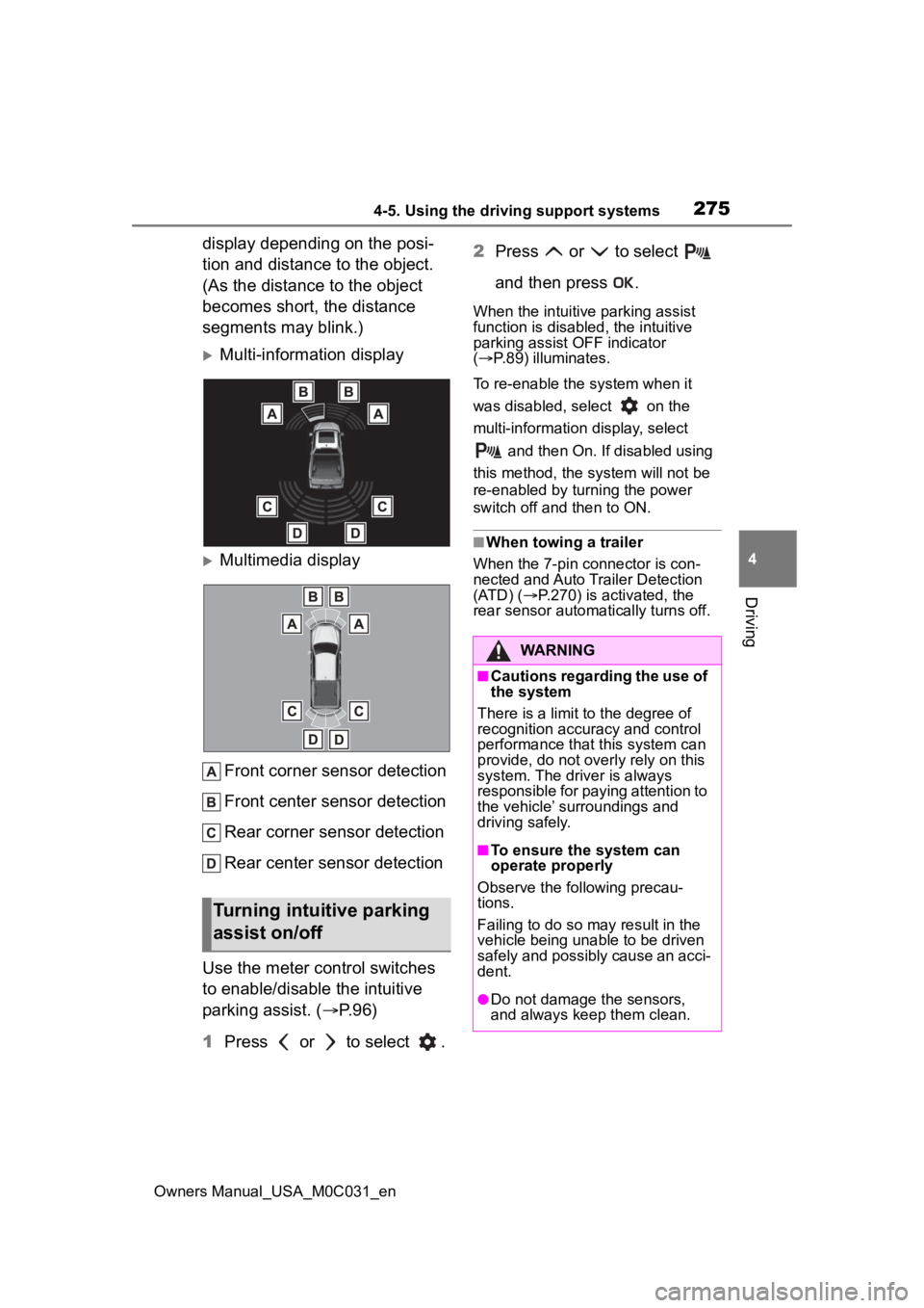
display depending on the posi-
tion and distance to the object.
(As the distance to the object
becomes short, the distance
segments may blink.)
Multi-information display
Multimedia display Front corner sensor detection
Front center sensor detection
Rear corner sensor detection
Rear center sensor detection
Use the meter control switches
to enable/disable the intuitive
parking assist. ( P.96)
1 Press or to select . 2
Press or to select
and then press .
When the intuitive parking assist
function is disabled, the intuitive
parking assist OFF indicator
( P.89) illuminates.
To re-enable the system when it
was disabled, select on the
multi-information display, select
and then On. If disabled using
this method, the system will not be
re-enabled by turning the power
switch off and then to ON.
■When towing a trailer
When the 7-pin connector is con-
nected and Auto Trailer Detection
(ATD) ( P.270) is activated, the
rear sensor automa tically turns off.
Turning intuitive parking
assist on/off
WARNING
■Cautions regarding the use of
the system
There is a limit t o the degree of
recognition accuracy and control
performance that this system can
provide, do not overly rely on this
system. The driver is always
responsible for paying attention to
the vehicle’ surroundings and
driving safely.
■To ensure the system can
operate properly
Observe the following precau-
tions.
Failing to do so may result in the
vehicle being unable to be driven
safely and possibly cause an acci-
dent.
●Do not damage the sensors,
and always keep them clean.
Page 276 of 618
2764-5. Using the driving support systems
Owners Manual_USA_M0C031_en
■The system can be operated
when
●The power switch is in ON.
●Intuitive parking assist function is
on.
●The vehicle speed is less than
about 6 mph (10 km/h).
●A shift position other than P is
selected.
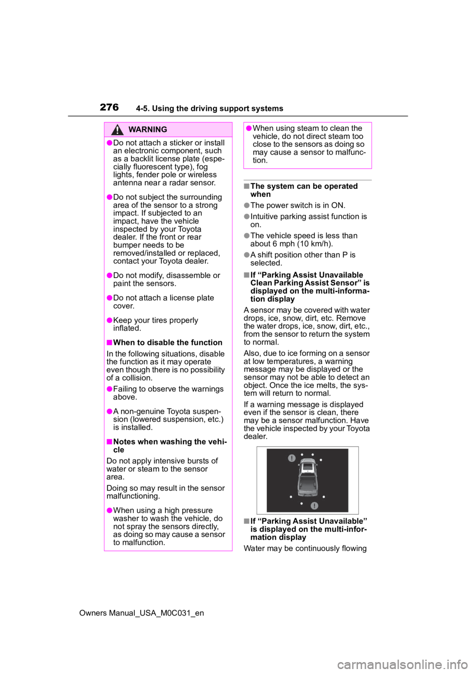
■If “Parking Assist Unavailable
Clean Parking Assist Sensor” is
displayed on the multi-informa-
tion display
A sensor may be covered with water
drops, ice, snow, dirt, etc. Remove
the water drops, ice, snow, dirt, etc.,
from the sensor to return the system
to normal.
Also, due to ice forming on a sensor
at low temperatures, a warning
message may be displayed or the
sensor may not be able to detect an
object. Once the ice melts, the sys-
tem will return to normal.
If a warning message is displayed
even if the sensor i s clean, there
may be a sensor malfunction. Have
the vehicle inspected by your Toyota
dealer.
■If “Parking Assist Unavailable”
is displayed on the multi-infor-
mation display
Water may be continuously flowing
WARNING
●Do not attach a sticker or install
an electronic component, such
as a backlit license plate (espe-
cially fluorescent type), fog
lights, fender pole or wireless
antenna near a radar sensor.
●Do not subject the surrounding
area of the sensor to a strong
impact. If subjected to an
impact, have the vehicle
inspected by your Toyota
dealer. If the fr ont or rear
bumper needs to be
removed/installed or replaced,
contact your Toyota dealer.
●Do not modify, disassemble or
paint the sensors.
●Do not attach a license plate
cover.
●Keep your tires properly
inflated.
■When to disable the function
In the following situations, disable
the function as it may operate
even though there is no possibility
of a collision.
●Failing to observe the warnings
above.
●A non-genuine Toyota suspen-
sion (lowered suspension, etc.)
is installed.
■Notes when washing the vehi-
cle
Do not apply intensive bursts of
water or steam to the sensor
area.
Doing so may result in the sensor
malfunctioning.
●When using a high pressure
washer to wash the vehicle, do
not spray the sensors directly,
as doing so may cause a sensor
to malfunction.
●When using steam to clean the
vehicle, do not direct steam too
close to the sensors as doing so
may cause a sensor to malfunc-
tion.
Page 277 of 618
2774-5. Using the driving support systems
Owners Manual_USA_M0C031_en
4
Driving
over the sensor surface, such as in
a heavy rain. When the system
determines that it is normal, the sys-
tem will return to normal.
■Sensor detection information
●The sensor’s detection areas are
limited to the areas around the
vehicle’ front and rear bumpers.
●The following situations may occur
during use.
• Depending on the shape of the
object and other factors, the
detection distance may shorten, or
detection may be impossible.
• Detection may be impossible if static objects draw too close to the
sensor.
• There will be a short delay
between static object detection
and display (warning buzzer
sounds). Even at low speeds,
there is a possibilit y that the object
will come within 11.9 in. (30 cm)
before the display is shown and
the warning buzzer sounds.
• It might be difficult to hear the
buzzer due to the volume of the
audio system or air flow noise of
the air conditioning system.
• It may be difficult to hear the sound of this system due to the
buzzers of other systems.
■Objects which the system may
not be properly detected
The shape of the object may pre-
vent the sensor from detecting it.
Pay particular attention to the follow-
ing objects:
●Wires, fences, ropes, etc.
●Cotton, snow and other materials
that absorb sound waves
●Sharply-angled objects
●Low objects
●Tall objects with upper sections
projecting outwards in the direc-
tion of your vehicle
■Situations in which the system
may not operate properly
Certain vehicle conditions and the surrounding environment may affect
the ability of a sensor to correctly
detect objects. Part
icular instances
where this may occur are listed
below.
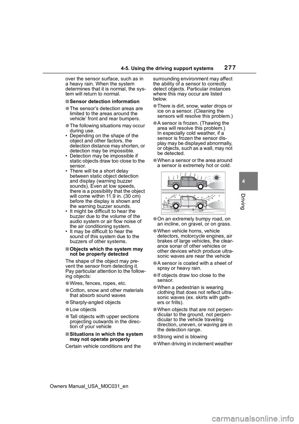
●There is dirt, snow, water drops or
ice on a sensor. (Cleaning the
sensors will resolve this problem.)
●A sensor is froz en. (Thawing the
area will resolve this problem.)
In especially cold weather, if a
sensor is frozen the sensor dis-
play may be displayed abnormally,
or objects, such as a wall, may not
be detected.
●When a sensor or the area around
a sensor is extremely hot or cold.
●On an extremely bumpy road, on
an incline, on gravel, or on grass.
●When vehicle horns, vehicle
detectors, motorcycle engines, air
brakes of large vehicles, the clear-
ance sonar of ot her vehicles or
other devices which produce ultra-
sonic waves are near the vehicle
●A sensor is coated with a sheet of
spray or heavy rain.
●If objects draw too close to the
sensor.
●When a pedestrian is wearing
clothing that does not reflect ultra-
sonic waves (ex. skirts with gath-
ers or frills).
●When objects that are not perpen-
dicular to the ground, not perpen-
dicular to the vehicle traveling
direction, uneven, or waving are in
the detection range.
●Strong wind is blowing
●When driving in inclement weather
Page 281 of 618
2814-5. Using the driving support systems
Owners Manual_USA_M0C031_en
4
Driving
The buzzers for the intuitive
parking assist and RCTA func-
tion (if equipped) will be muted
simultaneously.
Mute will be canceled automati-
cally in the following situations:
When the shift position is
changed.
When the vehicle speed
exceeds a certain speed.
When there is a malfunction
in a sensor or the system is
temporarily unavailable.
When the operating function
is disabled manually.
When the power switch is
turned off.RCTA (Rear Cross Traf-
fic Alert)
The RCTA function uses the
BSM rear side radar sen-
sors installed behind the
rear bumper. This function
is intended to assist the
driver in checking areas
that are not easily visible
when backing up.
WARNING
■Cautions regarding the use of
the system
There is a limit t o the degree of
recognition accuracy and control
performance that this system can
provide, do not overly rely on this
system. The driver is always
responsible for paying attention to
the vehicle’s su rroundings and
driving safely. ( P.267)
■To ensure the system can
operate properly
P. 2 6 8