display TOYOTA TUNDRA HYBRID 2022 Manual PDF
[x] Cancel search | Manufacturer: TOYOTA, Model Year: 2022, Model line: TUNDRA HYBRID, Model: TOYOTA TUNDRA HYBRID 2022Pages: 618, PDF Size: 19.91 MB
Page 252 of 618
2524-5. Using the driving support systems
Owners Manual_USA_M0C031_enoperating, a buzzer sounds and a
warning message urging the driver
to rest and the symbol shown in the
illustration are simultaneously dis-
played on the multi-information dis-
play.
Depending on the vehicle and road
conditions, the warning may not
operate.
■Warning message
If the follo wing warning message is
displayed on the multi-information
display and the LT A indicator illumi-
nates in orange, follow the appropri-
ate troubleshooting procedure. Also,
if a different warning message is
displayed, follow the instructions
displayed on the screen.
●“LTA Malfunction Visit Your
Dealer”
The system may not be operating
properly. Have the vehicle inspected
by your Toyota dealer.
●“LTA Unavailable”
The system is temporarily canceled
due to a malfuncti on in a sensor
other than the front camera. Turn
the LTA system off, wait for a little
while, and then turn the LTA system
back on.
●“LTA Unavailable at Current
Speed”
The function cannot be used as the
vehicle speed exceeds the LTA
operation range. Drive slower.
■Customization
Function settings can be changed.
(Customizable features: P.567)
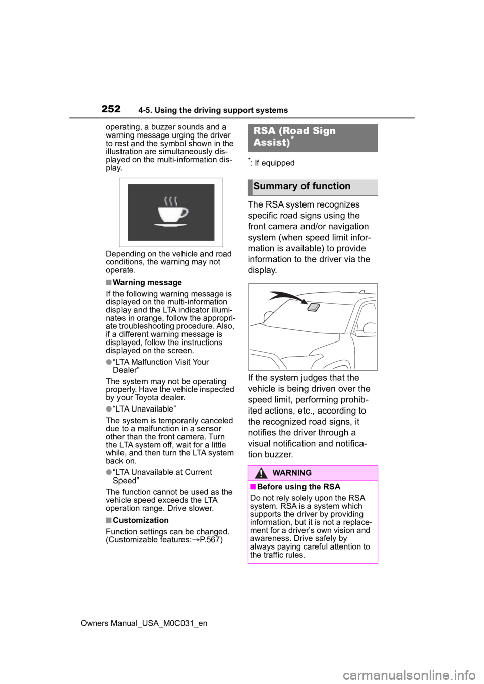
*: If equipped
The RSA system recognizes
specific road signs using the
front camera and/or navigation
system (when speed limit infor-
mation is available) to provide
information to the driver via the
display.
If the system judges that the
vehicle is being driven over the
speed limit, performing prohib-
ited actions, etc., according to
the recognized road signs, it
notifies the driver through a
visual notification and notifica-
tion buzzer.
RSA (Road Sign
Assist)*
Summary of function
WARNING
■Before using the RSA
Do not rely solely upon the RSA
system. RSA is a system which
supports the driver by providing
information, but it is not a replace-
ment for a driver’s own vision and
awareness. Drive safely by
always paying careful attention to
the traffic rules.
Page 253 of 618
2534-5. Using the driving support systems
Owners Manual_USA_M0C031_en
4
Driving
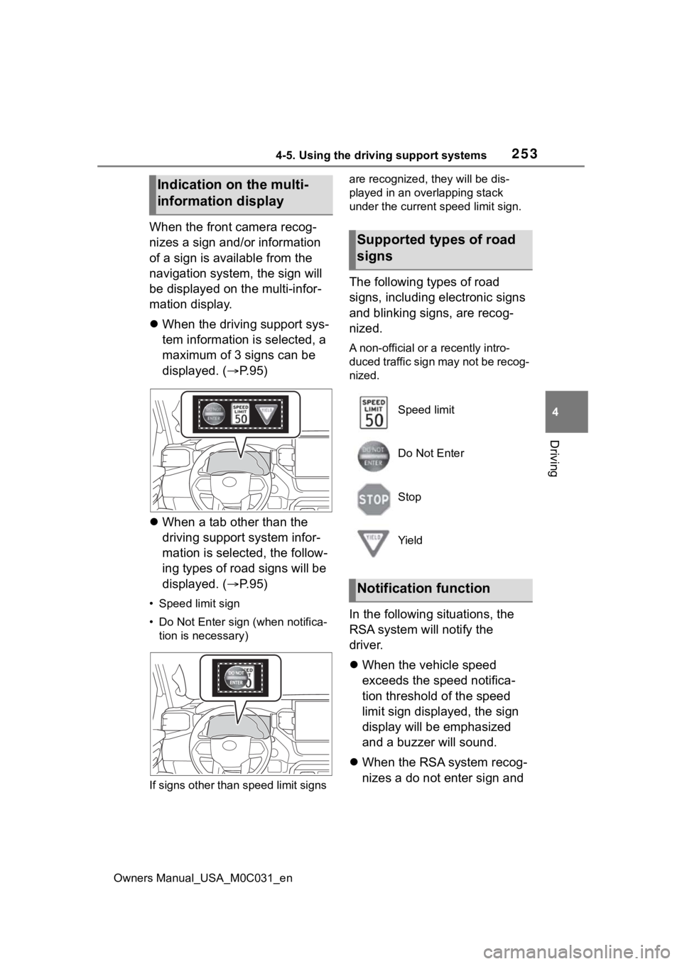
When the front camera recog-
nizes a sign and/or information
of a sign is available from the
navigation system, the sign will
be displayed on the multi-infor-
mation display.
When the driving support sys-
tem information is selected, a
maximum of 3 signs can be
displayed. ( P.95)
When a tab other than the
driving support system infor-
mation is selected, the follow-
ing types of road signs will be
displayed. ( P.95)
• Speed limit sign
•Do Not Enter sign (when notifica-
tion is necessary)
If signs other than speed limit signs are recognized, t
hey will be dis-
played in an overlapping stack
under the current speed limit sign.
The following types of road
signs, including el ectronic signs
and blinking signs, are recog-
nized.
A non-official or a recently intro-
duced traffic sign may not be recog-
nized.
In the following situations, the
RSA system will notify the
driver.
When the vehicle speed
exceeds the speed notifica-
tion threshold of the speed
limit sign displayed, the sign
display will be emphasized
and a buzzer will sound.
When the RSA system recog-
nizes a do not enter sign and
Indication on the multi-
information display
Supported types of road
signs
Speed limit
Do Not Enter
Stop
Yield
Notification function
Page 254 of 618
2544-5. Using the driving support systems
Owners Manual_USA_M0C031_en
determines that your vehicle
has entered a no-entry area,
the displayed sign will flash
and a buzzer will sound.
Depending on the situation, a
notification function may not
operate properly.
■Setting procedure
1 Press or of the meter
control switches and select .
2 Press or of the meter
control switches and select
“ RSA”, then press .
■Automatic turn-off of RSA sign
display
In the following si tuations, a dis-
played speed limit sign and/or do
not enter sign will stop being dis-
played automatically:
●No sign has been recognized for a
certain distance.
●The road changes due to a left or
right turn, etc.
In the following si tuations, stop and
yield signs will stop being displayed
automatically:
●The system determines that your
vehicle has passed the sign.
●The road changes due to a left or
right turn, etc.
■Conditions in which the func-
tion may not operate or detect
correctly
In the following situations, RSA
does not operate normally and may
not recognize signs, display the
incorrect sign, etc. However, this
does not indicate a malfunction.
●The front camera is misaligned
due to a strong impact being
applied to the sensor, etc.
●Dirt, snow, stickers, etc., are on the windshield near the front cam-
era.
●In inclement weather such as
heavy rain, fog, snow or sand
storms
●Light from an oncoming vehicle,
the sun, etc., enters the front cam-
era.
●The sign is dirty, faded, tilted or
bent.
●The contrast of electronic sign is
low.
●All or part of the
sign is hidden by
the leaves of a tree, a pole, etc.
●The sign is only visible to the front
camera for a short amount of time.
●The driving scene (turning, lane
change, etc.) is judged incorrectly.
●If a sign not appropriate for the
currently traveled lane, but the
sign exists directly after a freeway
branches, or in an adjacent lane
just before merging.
●Stickers are attached to the rear of
the preceding vehicle.
●A sign resembling a system com-
patible sign is recognized.
●Side road speed signs may be
detected and displayed (if posi-
tioned in sight of the front camera)
while the vehicle i s traveling on
the main road.
●Roundabout exit road speed signs
may be detected and displayed (if
positioned in si ght of the front
camera) while t raveling on a
roundabout.
●The front of the vehicle is raised or
lowered due to the carried load.
●The surrounding brightness is not
sufficient or changes suddenly.
●When a sign inte nded for trucks,
etc., is recognized.
●The navigation system map data
is outdated.
●The navigation system is not oper-
ating.
Page 255 of 618
2554-5. Using the driving support systems
Owners Manual_USA_M0C031_en
4
Driving
●The speed information displayed
on the meter and on the naviga-
tion system may be different due
to the navigation system using
map data.
■Speed limit sign display
If the power switc h was last turned
off while a speed limit sign was dis-
played on the multi-information dis-
play, the same sign displays again
when the power switch is turned to
ON.
■If “RSA Malfunction Visit Your
Dealer” is shown
The system may be malfunctioning.
Have the vehicle inspected by your
Toyota dealer.
■Customization
Some functions can be customized.
(Customizable features: P.568)
In vehicle-to-vehicle distance
control mode, the vehicle auto-
matically accelerates, deceler-
ates and stops to match the
speed changes of the preceding
vehicle even if the accelerator
pedal is not depressed. In con-
stant speed control mode, the
vehicle runs at a fixed speed.
Use the dynamic radar cruise
control with full-speed range on
freeways and highways.
Vehicle-to-vehicle distance
control mode ( P.258)
Constant speed control mode
( P.263)
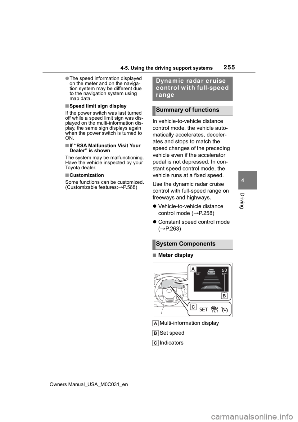
■Meter display
Multi-information display
Set speed
Indicators
Dynamic radar cruise
control with full-speed
range
Summary of functions
System Components
Page 260 of 618
2604-5. Using the driving support systems
Owners Manual_USA_M0C031_envehicle may accelerate when the
right turn signal is activated).
Example of acceleration
When there are no longer any preceding vehicles driving slower
than the set speed
The system accelerates until the set speed is reached. The system then
returns to constan t speed cruising.
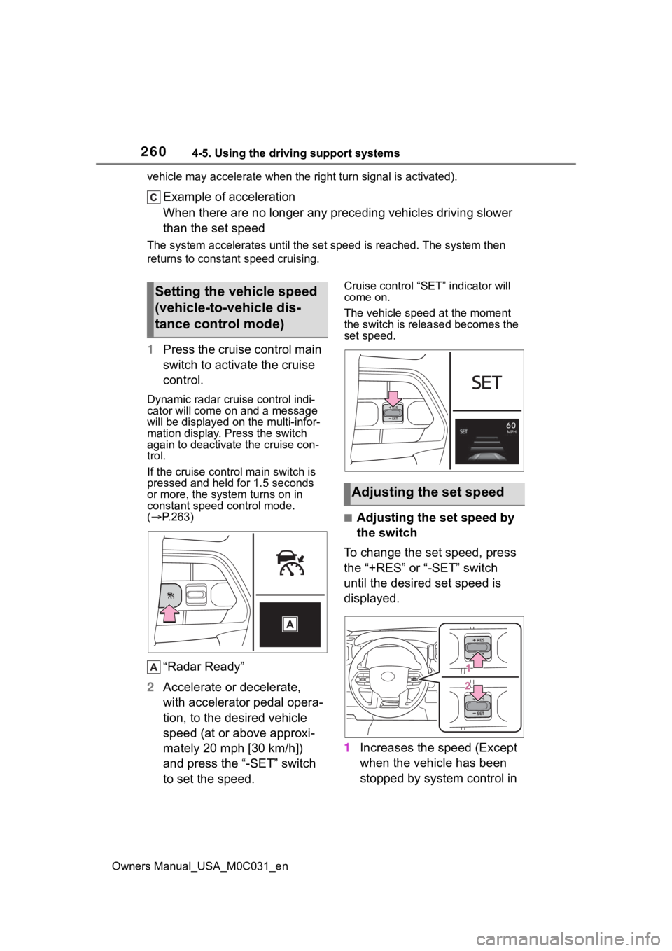
1Press the cruise control main
switch to activate the cruise
control.
Dynamic radar cruise control indi-
cator will come on and a message
will be displayed on the multi-infor-
mation display. Press the switch
again to deactivate the cruise con-
trol.
If the cruise cont rol main switch is
pressed and held for 1.5 seconds
or more, the syste m turns on in
constant speed control mode.
( P.263)
“Radar Ready”
2 Accelerate or decelerate,
with accelerator pedal opera-
tion, to the desired vehicle
speed (at or above approxi-
mately 20 mph [30 km/h])
and press the “-SET” switch
to set the speed.
Cruise control “SET” indicator will
come on.
The vehicle speed at the moment
the switch is released becomes the
set speed.
■Adjusting the set speed by
the switch
To change the set speed, press
the “+RES” or “-SET” switch
until the desired set speed is
displayed.
1 Increases the speed (Except
when the vehicle has been
stopped by system control in
Setting the vehicle speed
(vehicle-to-vehicle dis-
tance control mode)
Adjusting the set speed
Page 261 of 618
2614-5. Using the driving support systems
Owners Manual_USA_M0C031_en
4
Driving
vehicle-to-vehicle distance
control mode)
2 Decreases the speed
Fine adjustment: Press the switch.
Large adjustment: Press and hold
the switch to change the speed,
and release when the desired
speed is reached.
In the vehicle-to-vehicle dis-
tance control mode, the set
speed will be increased or
decreased as follows:
For the U.S. mainland, Hawaii
Fine adjustment: By 1 mph (1.6
km/h)
*1 or 1 km/h (0.6mph)*2 each
time the switch is pressed
Large adjustment: Increases or
decreases in 1mph (1.6 km/h)
*1 or
1 km/h (0.6 mph)
*2 increments for
as long as the switch is held
Except for the U.S. mainland
and Hawaii
Fine adjustment: By 1 mph (1.6
km/h)
*1 or 1 km/h (0.6mph)*2 each
time the switch is pressed
Large adjustment: Increases or
decreases in 5 mph (8 km/h)
*1 or 5
km/h (3.1 mph)
*2 increments for as
long as the switch is held
In the constant speed control
mode ( P.263), the set speed
will be increased or decreased
as follows:
Fine adjustment: By 1 mph (1.6
km/h)
*1 or 1 km/h (0.6 mph)*2 each
time the switch is pressed
Large adjustment: The speed will
continue to change while the switch is held.
*1: When the set speed is shown in
“MPH”
*2: When the set speed is shown in “km/h”
■Increasing the set speed by
the accelerator pedal
1 Accelerate with accelerator
pedal operation to the
desired vehicle speed
2 Press the “-SET” switch
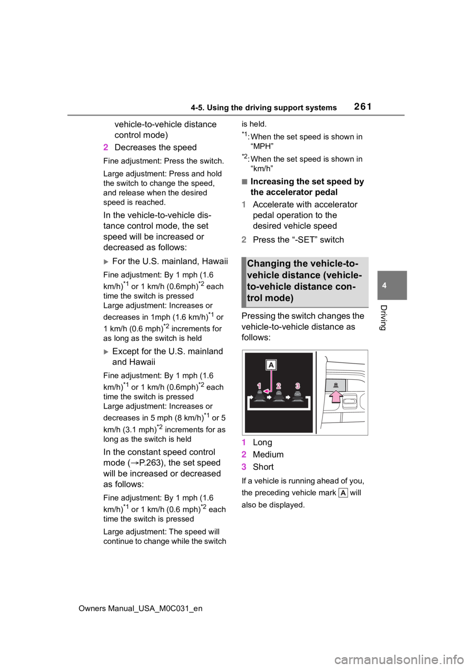
Pressing the switch changes the
vehicle-to-vehicle distance as
follows:
1 Long
2 Medium
3 Short
If a vehicle is running ahead of you,
the preceding vehicle mark will
also be displayed.
Changing the vehicle-to-
vehicle distance (vehicle-
to-vehicle distance con-
trol mode)
Page 263 of 618
2634-5. Using the driving support systems
Owners Manual_USA_M0C031_en
4
Driving
When your vehicle is too close
to a vehicle ahead, and suffi-
cient automatic deceleration via
the cruise control is not possi-
ble, the display will flash and the
buzzer will sound to alert the
driver. An example of this would
be if another driver cuts in front
of you while you are following a
vehicle. Depress the brake
pedal to ensure an appropriate
vehicle-to-vehicle distance.
■Warnings may not occur
when
In the following instances, warn-
ings may not occur even when
the vehicle-to-vehicle distance is
small.
When the speed of the pre-
ceding vehicle matches or
exceeds your vehicle speed
When the preceding vehicle is
traveling at an extremely slow
speed
Immediately after the cruise
control speed was set
When depressing the acceler-
ator pedal
When constant speed control
mode is selected, your vehicle
will maintain a set speed without
controlling the vehicle-to-vehi-
cle distance. Select this mode
only when vehicle- to-vehicle dis-
tance control mode does not
function correctly due to a dirty
radar, etc.
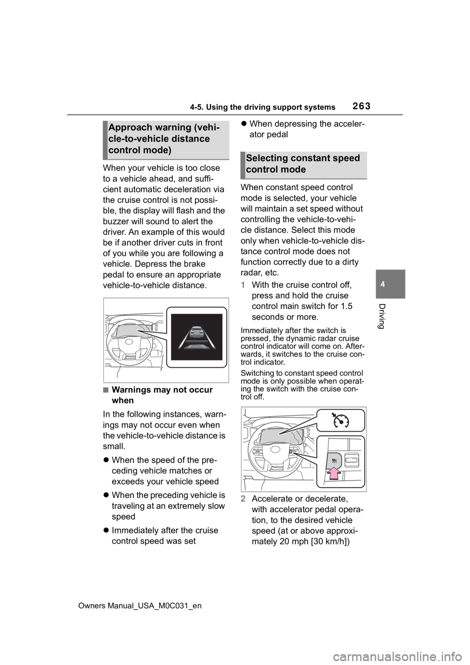
1 With the cruise control off,
press and hold the cruise
control main switch for 1.5
seconds or more.
Immediately after the switch is
pressed, the dynamic radar cruise
control indicator will come on. After-
wards, it switches to the cruise con-
trol indicator.
Switching to const ant speed control
mode is only possible when operat-
ing the switch with the cruise con-
trol off.
2 Accelerate or decelerate,
with accelerator pedal opera-
tion, to the desired vehicle
speed (at or above approxi-
mately 20 mph [30 km/h])
Approach warning (vehi-
cle-to-vehicle distance
control mode)
Selecting constant speed
control mode
Page 265 of 618
2654-5. Using the driving support systems
Owners Manual_USA_M0C031_en
4
Driving
any reasons other than the above,
there may be a malfunction in the
system. Contact your Toyota dealer.
■Automatic cancelation of con-
stant speed control mode
Constant speed control mode is
automatically cance led in the follow-
ing situations:
●Actual vehicle speed is more than
approximately 10 mph (16 km/h)
below the set vehicle speed.
●Actual vehicle speed falls below
approximately 20 mph (30 km/h).
●VSC is activated.
●TRAC is activated for a period of
time.
●When the VSC or TRAC system is
turned off.
●When the brake control or output
restriction control of a driving sup-
port system operates. (For exam-
ple: Pre-Collision System, Drive-
Start Control)
●The center differential lock/unlock
is not completed within 5 seconds
while the cruise con trol system is
on.
●The parking brake is operated.
If constant speed control mode is
automatically canceled for any rea-
sons other than the above, there
may be a malfunction in the system.
Contact your Toyota dealer.
■Brake operation
A brake operation sound may be
heard and the brake pedal response
may change, but the se are not mal-
functions.
■Warning messages and buzzers
for dynamic radar cruise con-
trol with full-speed range
Warning messages and buzzers are
used to indicate a system malfunc-
tion or to inform the driver of the
need for caution while driving. If a
warning message is shown on the
multi-information display, read the
message and follow the instruc- tions.(
P.228, 511)
■When the sensor may not be
correctly detecting the vehicle
ahead
In the case of the following and
depending on the conditions, oper-
ate the brake pedal when decelera-
tion of the system is insufficient or
operate the accelerator pedal when
acceleration is required.
As the sensor may not be able to
correctly detect th ese types of vehi-
cles, the approach warning
( P.263) may not be activated.
●Vehicles that cut in suddenly
●Vehicles traveling at low speeds
●Vehicles that are not moving in the
same lane
●Vehicles with small rear ends
(trailers with no load on board,
etc.)
●Motorcycles traveling in the same
lane
●When water or snow thrown up by
the surrounding vehicles hinders
the detecting of the sensor
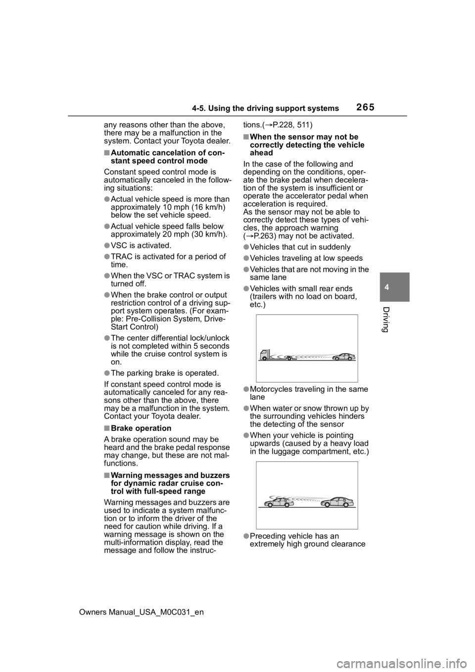
●When your vehicle is pointing
upwards (caused by a heavy load
in the luggage compartment, etc.)
●Preceding vehicle has an
extremely high ground clearance
Page 267 of 618
2674-5. Using the driving support systems
Owners Manual_USA_M0C031_en
4
Driving
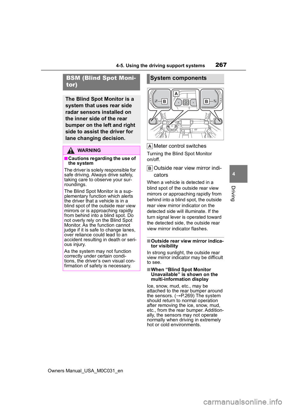
Meter control switches
Turning the Blind Spot Monitor
on/off.
Outside rear view mirror indi-
cators
When a vehicle is detected in a
blind spot of the outside rear view
mirrors or approaching rapidly from
behind into a blind spot, the outside
rear view mirror indicator on the
detected side will illuminate. If the
turn signal lever is operated toward
the detected side, the outside rear
view mirror indicator flashes.
■Outside rear vie w mirror indica-
tor visibility
In strong sunlight, the outside rear
view mirror indicator may be difficult
to see.
■When “Blind Spot Monitor
Unavailable” is shown on the
multi-information display
Ice, snow, mud, etc., may be
attached to the rear bumper around
the sensors. ( P.269) The system
should return to normal operation
after removing the ice, snow, mud,
etc., from the rear bumper. Addition-
ally, the sensors may not operate
normally when drivin g in extremely
hot or cold environments.
BSM (Blind Spot Moni-
tor)
The Blind Spot Monitor is a
system that uses rear side
radar sensors installed on
the inner side of the rear
bumper on the left and right
side to assist the driver for
lane changing decision.
WARNING
■Cautions regarding the use of
the system
The driver is solely responsible for
safe driving. Always drive safely,
taking care to o bserve your sur-
roundings.
The Blind Spot Monitor is a sup-
plementary function which alerts
the driver that a v ehicle is in a
blind spot of the outside rear view
mirrors or is approaching rapidly
from behind into a blind spot. Do
not overly rely on the Blind Spot
Monitor. As the function cannot
judge if it is safe to change lanes,
over reliance could lead to an
accident resulting in death or seri-
ous injury.
As the system may not function
correctly under certain condi-
tions, the driver’s own visual con-
firmation of safety is necessary.
System components
Page 268 of 618
2684-5. Using the driving support systems
Owners Manual_USA_M0C031_en
■When “Blind Spot Monitor Mal-
function Visit Your Dealer” is
shown on the multi-information
display
There may be a sensor malfunction
or misaligned. Have the vehicle
inspected by your Toyota dealer.
■Customization
Some functions can be customized.
( P.568)
■Certification
P. 6 1 4
WARNING
■To ensure the system can
operate properly
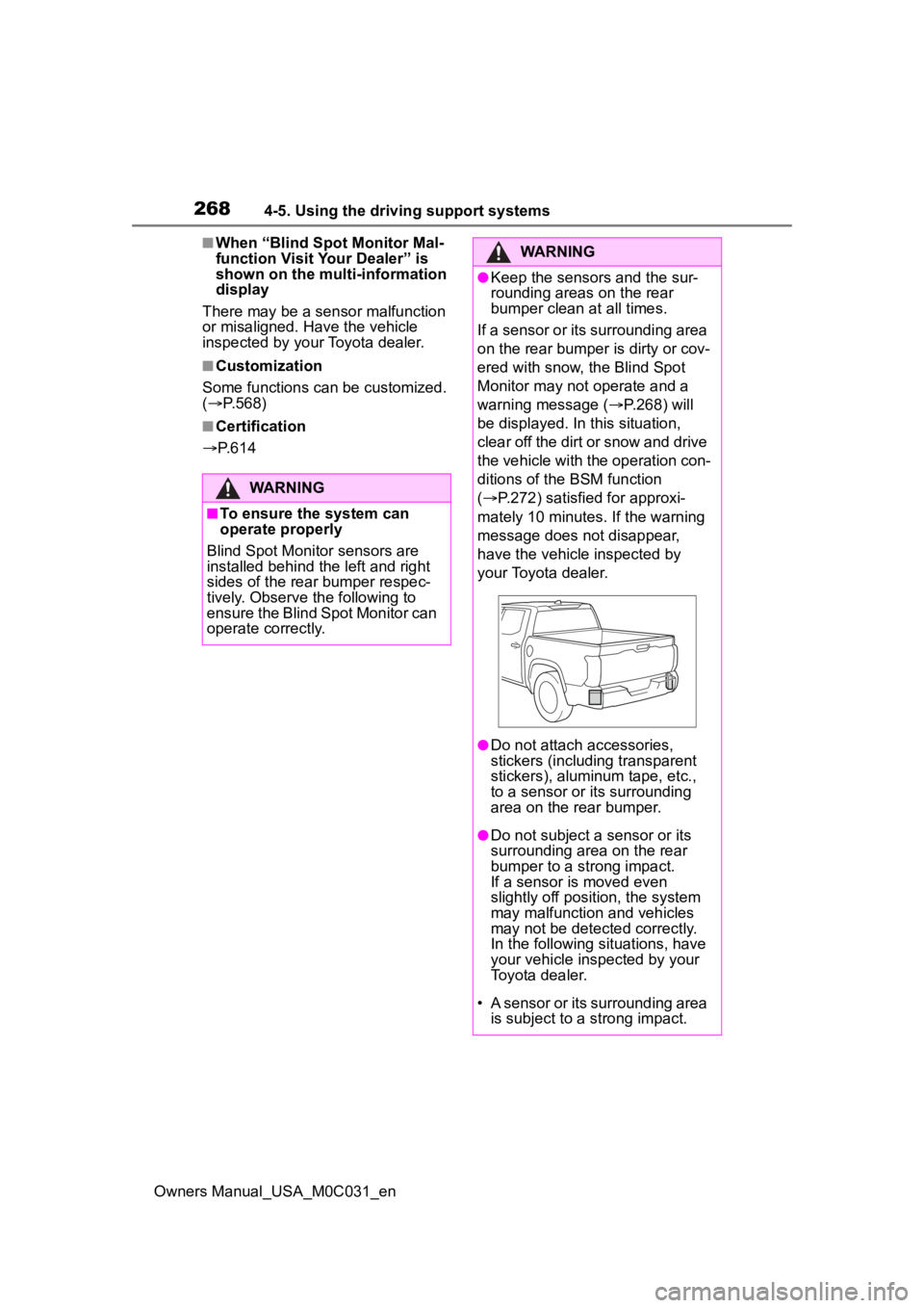
Blind Spot Monitor sensors are
installed behind the left and right
sides of the rear bumper respec-
tively. Observe the following to
ensure the Blind Spot Monitor can
operate correctly.
WARNING
●Keep the sensors and the sur-
rounding areas on the rear
bumper clean at all times.
If a sensor or its surrounding area
on the rear bumper is dirty or cov-
ered with snow, the Blind Spot
Monitor may not operate and a
warning message ( P.268) will
be displayed. In this situation,
clear off the dirt or snow and drive
the vehicle with the operation con-
ditions of the BSM function
( P.272) satisfied for approxi-
mately 10 minutes. If the warning
message does not disappear,
have the vehicle inspected by
your Toyota dealer.
●Do not attach a ccessories,
stickers (including transparent
stickers), aluminum tape, etc.,
to a sensor or its surrounding
area on the rear bumper.
●Do not subject a sensor or its
surrounding area on the rear
bumper to a strong impact.
If a sensor is moved even
slightly off position, the system
may malfunction and vehicles
may not be detected correctly.
In the following si tuations, have
your vehicle inspected by your
Toyota dealer.
• A sensor or its surrounding area is subject to a strong impact.