length TOYOTA TUNDRA HYBRID 2022 Owners Manual
[x] Cancel search | Manufacturer: TOYOTA, Model Year: 2022, Model line: TUNDRA HYBRID, Model: TOYOTA TUNDRA HYBRID 2022Pages: 618, PDF Size: 19.91 MB
Page 98 of 618
982-1. Instrument cluster
Owners Manual_USA_M0C031_ention. As a result, the actual dis-
tance that can be driven may differ
from that displayed.
●When only a small amount of fuel
is added to the tank, the display
may not be updated. When refuel-
ing, turn the power
switch to OFF.
If the vehicle is refueled without
turning the power switch to OFF,
the display may not be updated.
●When “Refuel” is displayed, the
remaining fuel amount is low and
the distance that can be driven
with the remaining fuel cannot be
calculated. Refuel immediately.
■Hybrid System Indicator
The Hybrid System Indicator will not
operate in the following situations:
●The “READY” indicator is not illu-
minated.
●The shift lever is in a range other
than D or S.
Select to display the following
navigation system-linked infor-
mation:
Route guidance to destination
Compass display (heading-up
display)
Select to enable selection of an
audio source or track on the
meter using the meter control
switches.
This menu icon can be set to be
displayed/not displayed in .
■Trailer brake
Displays trailer brake control
status ( P.380) and trailer
type
*.
*: To select the trailer, press and
hold the meter control switch.
( P.100)
■Trailer Mode BSM
Displays trailer length
* and
trailer blind spot status
( P.267).
*: To select the trailer, press and
hold the meter control switch.
( P.100)
■Drive information
2 items that are selected using
the “Drive Info Items” setting
(average speed, distance and
total time) can be displayed ver-
tically.
The displayed information
changes according to the “Drive
Info Type” setting (since the sys-
tem was started or between
resets). ( P. 9 9 )
Use the displayed information as a
reference only.
Following items will be displayed.
“Trip”
• “Average Speed”: Displays the
average vehicle speed since
hybrid system start
*
Navigation system-linked
display
Audio system-linked dis-
play
Vehicle information dis-
play
Page 100 of 618
1002-1. Instrument cluster
Owners Manual_USA_M0C031_en
■Changing settings of the
trailer type
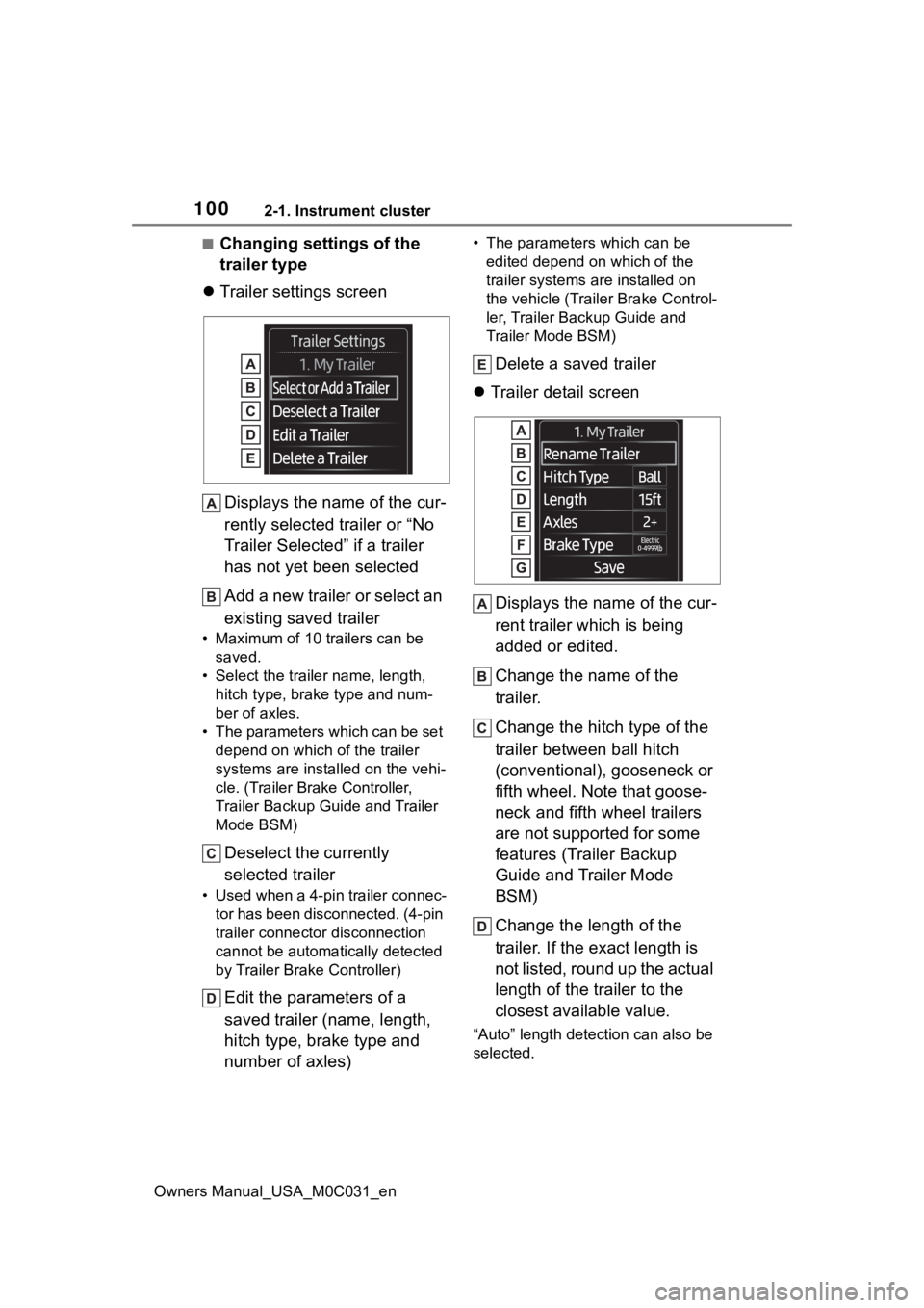
Trailer settings screen
Displays the name of the cur-
rently selected trailer or “No
Trailer Selected” if a trailer
has not yet been selected
Add a new trailer or select an
existing saved trailer
• Maximum of 10 trailers can be saved.
• Select the trailer name, length, hitch type, brake type and num-
ber of axles.
• The parameters which can be set depend on which of the trailer
systems are installed on the vehi-
cle. (Trailer Brake Controller,
Trailer Backup Guide and Trailer
Mode BSM)
Deselect the currently
selected trailer
• Used when a 4-pin trailer connec-tor has been disconnected. (4-pin
trailer connector disconnection
cannot be automatically detected
by Trailer Brake Controller)
Edit the parameters of a
saved trailer (name, length,
hitch type, brake type and
number of axles)
• The parameters which can be edited depend on which of the
trailer systems are installed on
the vehicle (Trailer Brake Control-
ler, Trailer Backup Guide and
Trailer Mode BSM)
Delete a saved trailer
Trailer detail screen
Displays the name of the cur-
rent trailer which is being
added or edited.
Change the name of the
trailer.
Change the hitch type of the
trailer between ball hitch
(conventional), gooseneck or
fifth wheel. Note that goose-
neck and fifth wheel trailers
are not supported for some
features (Trailer Backup
Guide and Trailer Mode
BSM)
Change the length of the
trailer. If the exact length is
not listed, round up the actual
length of the trailer to the
closest available value.
“Auto” length dete ction can also be
selected.
Page 133 of 618

1333-3. Adjusting the seats
Owners Manual_USA_M0C031_en
3
Before driving
3-3.Adjusting the seats
Seat position adjustment
Seatback angle adjustment
Seat cushion (front) angle
adjustment
Vertical height adjustment
Seat cushion length adjust-
ment (if equipped)
Lumbar support height
adjustment (if equipped)
Lumbar support adjustment
■When adjusting the seat
●Make sure that any surrounding
passengers or ob jects are not contact the seat.
●Take care when adjusting the seat
so that the head restraint does not
touch the ceiling.
■Power easy access system (if
equipped)
The driver’s seat and steering wheel
move in accordance with power
switch mode and th e driver’s seat
belt condition. ( P.137)
Front seats
The seats can be adjusted
(longitudinally, vertically,
etc.). Adjust the seat to
ensure the correct driving
posture.
Adjustment procedureWARNING
■When adjusting the seat posi-
tion
●Take care when adjusting the
seat position to ensure that
other passengers are not
injured by the moving seat.
●Do not put your hands under the
seat or near the moving parts to
avoid injury.
Fingers or hands may become
jammed in the seat mechanism.
●Make sure to leave enough
space around the feet so they
do not get stuck.
■Seat adjustment
To reduce the risk of sliding under
the lap belt during a collision, do
not recline the se at more than
necessary.
If the seat is too reclined, the lap
belt may slide past the hips and
apply restraint for ces directly to
the abdomen, or your neck may
contact the shoulder belt, increas-
ing the risk of death or serious
injury in the event of an accident.
Adjustments should not be made
while driving as the seat may
unexpectedly move and cause
the driver to lose control of the
vehicle.
Page 189 of 618
1894-1. Before driving
Owners Manual_USA_M0C031_en
4
Driving
Trailer ball load rating
Matches or exceeds the gross
trailer weight rat ing of the trailer.
Shank length
Protrudes beyond the bottom of the
lock washer and nut at least 2
threads.
Shank diameter
Matches the ball mount hole diame-
ter size.
Ball diameter
Matches the size of the trailer cou-
pler. Most couplers are stamped
with the required tr ailer ball size.
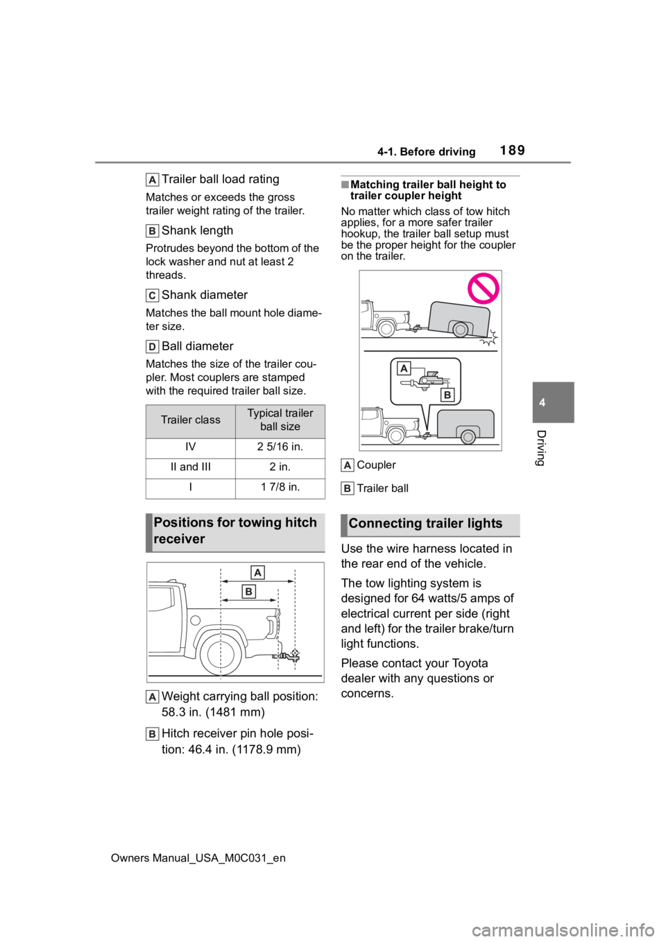
Weight carrying ball position:
58.3 in. (1481 mm)
Hitch receiver pin hole posi-
tion: 46.4 in. (1178.9 mm)
■Matching trailer ball height to
trailer coupler height
No matter wh ich class of tow hitch
applies, for a mor e safer trailer
hookup, the trailer ball setup must
be the proper height for the coupler
on the trailer.
Coupler
Trailer ball
Use the wire harness located in
the rear end of the vehicle.
The tow lighting system is
designed for 64 watts/5 amps of
electrical current per side (right
and left) for the trailer brake/turn
light functions.
Please contact your Toyota
dealer with any questions or
concerns.
Trailer classTypical trailer ball size
IV2 5/16 in.
II and III2 in.
I1 7/8 in.
Positions for towing hitch
receiverConnecting trailer lights
Page 192 of 618

1924-1. Before driving
Owners Manual_USA_M0C031_en
sway) increases as speed
increases. Exceeding speed
limits may cause loss of con-
trol.
Before starting out, check the
trailer lights, tires and the
vehicle-trailer connections.
Recheck after driving a short
distance.
Practice turning, stopping and
reversing with the trailer
attached in an area away
from traffic until you become
accustomed to the feel of the
vehicle-trailer combination.
Reversing with a trailer
attached is difficult and
requires practice. Grip the
bottom of the steering wheel
and move your hand to the
left to move the trailer to the
left. Move your hand to the
right to move the trailer to the
right. (This is generally oppo-
site to reversing without a
trailer attached.) Avoid sharp
or prolonged turning. Have
someone guide you when
reversing to reduce the risk of
an accident.
As stopping distance is
increased when towing a
trailer, vehicle-to-vehicle dis-
tance should be increased.
For each 10 mph (16 km/h) of
speed, allow at least one
vehicle and trailer length.
Avoid sudden braking as you
may skid, resulting in the trailer jackknifing and a loss of
vehicle control. This is espe-
cially true on wet or slippery
surfaces.
Avoid jerky starts or sudden
acceleration.
Avoid jerky steering and
sharp turns, and slow down
before making a turn.
Note that when making a turn,
the trailer wheels will be
closer than the vehicle wheels
to the inside of the turn. Com-
pensate by making a wider
than normal turning radius.
Slow down before making a
turn, in crosswinds, on wet or
slippery surfaces, etc.
Increasing vehicle speed can
destabilize the trailer.
Take care when passing other
vehicles. Passing requires
considerable distance. After
passing a vehicle, do not for-
get the length of your trailer,
and be sure you have plenty
of room before changing
lanes.
Instability happens more fre-
quently when descending
steep or long downhill grades.
Before descending, slow
down and downshift. Do not
make sudden downshifts
while descending steep or
long downhill grades.
Avoid holding the brake pedal
down too long or applying the
Page 269 of 618
2694-5. Using the driving support systems
Owners Manual_USA_M0C031_en
4
Driving
■Turning the Blind Spot Mon-
itor on/off
Use the meter control switches
to turn on/off the function.
( P. 9 6 )
1 Press or to select .
2 Press or to select “
BSM” and then press .
When the BSM function is disabled,
the BSM OFF indicator ( P.89) illu-
minates. (Each time the power
switch is turned off then changed to
ON, the Blind Spo t Monitor will be
enabled automatically.)
■Setting the trailer type
Use the meter control switches
to select the trailer type.
( P. 9 6 )
1 Press or to select . 2
Press or to select
“Trailer Settings” and then
press and hold .
3 According to the display,
select the desired setting and
then press . ( P.100)
■Auto Trailer Detection (ATD)
Auto Trailer Detection (ATD) detects
if a trailer is atta ched by using the
Trailer Brake Controller (TBC) or the
Blind Spot Monitor (BSM) sensors.
●Trailers that use TBC can be
detected by using the 7-pin trailer
brake connectors.
●Other types of trailers can be
detected using the BSM sensors.
●When a trailer is detected via BSM
or TBC, RCTA function will be dis-
abled.
●As soon as the trailer is detected,
the detection area will be
extended to a maximum length of
approximately 16 ft. (15 m) from
the rear bumper of the truck.
●If the trailer does not have a 7-pin
connector, or the 7-pin connector
is not engaged, the trailer is
detected via the BSM sensor. In
this case PKSB and Intuitive park-
ing assist functio ns will not be dis-
abled.
●For trailer auto d etection without
engagement of 7-pin connector,
the vehicle should be moving for-
ward at speed of above 0.6 mph
(1 km/h) for at l east 10 seconds.
●ATD function is triggered at every
power switch on/of f cycle or if the
vehicle is stopped in shift the shift
lever is in P or N for more than 90
seconds.
●Trailer detection vis BSM sensors
may be delayed if the vehicle is in
a crowded environment such as
• If the surroundin
g area of a sen-
sor is scratched or dented, or
part of them has become dis-
connected.
●Do not disassemble the sensor.
●Do not modify the sensor or sur-
rounding area on the rear
bumper.
●If a sensor or th e rear bumper
needs to be removed/installed
or replaced, contact your Toyota
dealer.
●Do not paint the rear bumper
any color other than an official
To y o t a c o l o r.
Changing settings of the
Blind Spot Monitor
Page 270 of 618
2704-5. Using the driving support systems
Owners Manual_USA_M0C031_enbusy parking lot, area surrounded
with trees (camping ground) or in
an environment with objects in the
immediate environment that pre-
vent sensors from sufficiently
detecting the trailer.
■Trailer Length Detection (TLD)
●Once a trailer is detected and if
the trailer length in the meter is
selected as “Auto”, the TLD func-
tion will estimate the
trailer length
using the Blind Spot Monitor sen-
sors. In order to estimate
the trailer length
with TLD function and detection
area, make at least two 90 degree
turns.
If the trailer length is entered manu-
ally via multi-information display
input, the detection area is also
adjusted to exceed the length of the
trailer.
●Depending on some trailer types
and the dimensions of the trailer
TMW performance may be
degraded.
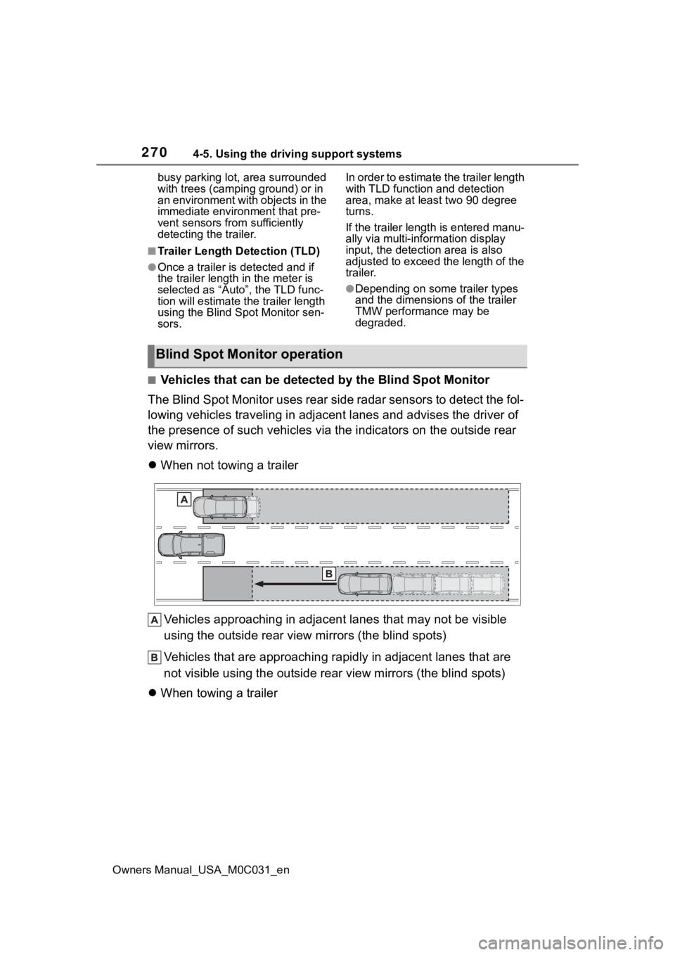
■Vehicles that can be detected by the Blind Spot Monitor
The Blind Spot Monitor uses rear side radar sensors to detect the fol-
lowing vehicles traveling in adjacent lanes and advises the dri ver of
the presence of such vehicles v ia the indicators on the outside rear
view mirrors.
When not towing a trailer
Vehicles approaching in adjacen t lanes that may not be visible
using the outside rear view mirrors (the blind spots)
Vehicles that are approaching r apidly in adjacent lanes that are
not visible using the outside rear view mirrors (the blind spots)
When towing a trailer
Blind Spot Monitor operation
Page 272 of 618
2724-5. Using the driving support systems
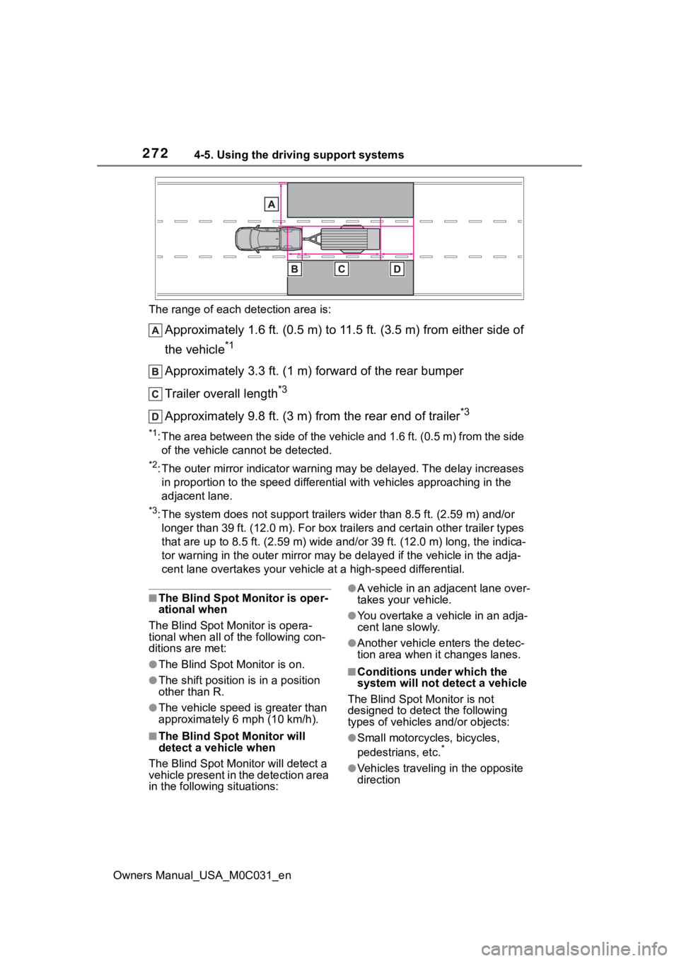
Owners Manual_USA_M0C031_enThe range of each detection area is:
Approximately 1.6 ft. (0.5 m) to 11.5 ft. (3.5 m) from either s
ide of
the vehicle
*1
Approximately 3.3 ft. (1 m) forward of the rear bumper
Trailer overall length
*3
Approximately 9.8 ft. (3 m) from the rear end of trailer*3
*1: The area between the side of the vehicle and 1.6 ft. (0.5 m) f rom the side
of the vehicle cannot be detected.
*2: The outer mirror indicator warning may be delayed. The delay i ncreases
in proportion to the speed differential with vehicles approaching in the
adjacent lane.
*3: The system does not support trailers wider than 8.5 ft. (2.59 m) and/or
longer than 39 ft. (12.0 m). For box trailers and certain other trailer types
that are up to 8.5 ft. (2.59 m) wide and/or 39 ft. (12.0 m) lon g, the indica-
tor warning in t he outer mirror may be de layed if the vehicle in the adja-
cent lane overtakes your vehicle at a high-speed differential.
■The Blind Spot Monitor is oper-
ational when
The Blind Spot Monitor is opera-
tional when all of the following con-
ditions are met:
●The Blind Spot Monitor is on.
●The shift position is in a position
other than R.
●The vehicle speed is greater than
approximately 6 mph (10 km/h).
■The Blind Spot Monitor will
detect a veh icle when
The Blind Spot Mon itor will detect a
vehicle present in the detection area
in the followin g situations:
●A vehicle in an adjacent lane over-
takes your vehicle.
●You overtake a vehicle in an adja-
cent lane slowly.
●Another vehicle enters the detec-
tion area when it changes lanes.
■Conditions under which the
system will not detect a vehicle
The Blind Spot Monitor is not
designed to detect the following
types of vehicles and/or objects:
●Small motorcycles, bicycles,
pedestrians, etc.*
●Vehicles traveling in the opposite
direction
Page 333 of 618
3334-5. Using the driving support systems
Owners Manual_USA_M0C031_en
4
Driving
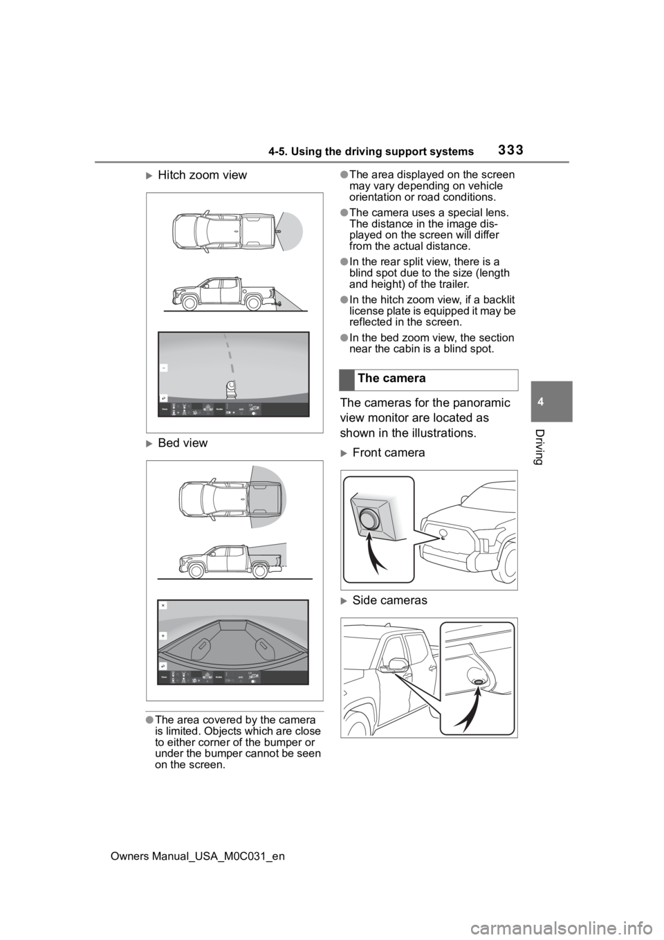
Hitch zoom view
Bed view
●The area covered by the camera
is limited. Objects which are close
to either corner of the bumper or
under the bumper cannot be seen
on the screen.
●The area displayed on the screen
may vary depending on vehicle
orientation or road conditions.
●The camera uses a special lens.
The distance in the image dis-
played on the screen will differ
from the actual distance.
●In the rear split view, there is a
blind spot due to the size (length
and height) of the trailer.
●In the hitch zoom view, if a backlit
license plate is equipped it may be
reflected in the screen.
●In the bed zoom view, the section
near the cabin is a blind spot.
The cameras for the panoramic
view monitor are located as
shown in the illustrations.
Front camera
Side cameras
The camera
Page 382 of 618
3824-5. Using the driving support systems
Owners Manual_USA_M0C031_en
*: If equipped
1Select “Trailer Settings” from
( P.96) on the multi-
information display and add a
trailer according to the dis-
play. 2
Press the switch to turn the
system ON.
3 Continue or reselect the
trailer in the message dis-
played on the multi-informa-
tion display.
When the selected trailer is being
used for the first time, setup (cali-
bration) is nece ssary (→P.384).
Once calibration is completed, it is
retained for future use and the sys-
tem will automatically detect the
trailer.
The driver needs to change the
trailer selection when using a differ-
ent trailer. The system does not
automatically recognize the trailer
from the saved trailers list.
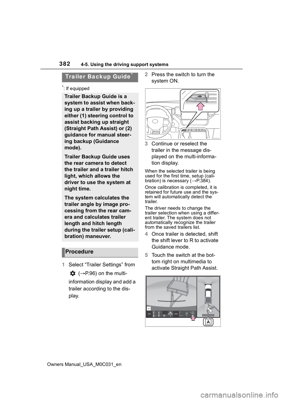
4 Once trailer is detected, shift
the shift lever to R to activate
Guidance mode.
5 Touch the switch at the bot-
tom right on multimedia to
activate Straight Path Assist.
Trailer Backup Guide*
Trailer Backup Guide is a
system to assist when back-
ing up a trailer by providing
either (1) steering control to
assist backing up straight
(Straight Path Assist) or (2)
guidance for manual steer-
ing backup (Guidance
mode).
Trailer Backup Guide uses
the rear camera to detect
the trailer and a trailer hitch
light, which allows the
driver to use the system at
night time.
The system calculates the
trailer angle by image pro-
cessing from the rear cam-
era and calculates trailer
length and hitch length
during the trailer setup (cali-
bration) maneuver.
Procedure