width TOYOTA TUNDRA HYBRID 2023 User Guide
[x] Cancel search | Manufacturer: TOYOTA, Model Year: 2023, Model line: TUNDRA HYBRID, Model: TOYOTA TUNDRA HYBRID 2023Pages: 618, PDF Size: 13.67 MB
Page 327 of 618
3274-5. Using the driving support systems
Owners Manual_USA_M0C052_en
4
Driving
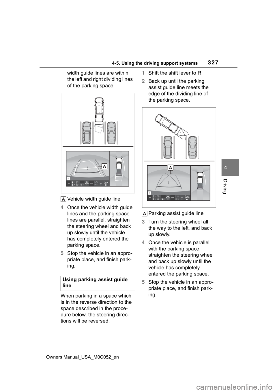
width guide lines are within
the left and right dividing lines
of the parking space.
Vehicle width guide line
4 Once the vehicle width guide
lines and the parking space
lines are parallel, straighten
the steering wheel and back
up slowly until the vehicle
has completely entered the
parking space.
5 Stop the vehicle in an appro-
priate place, and finish park-
ing.
When parking in a space which
is in the reverse direction to the
space described in the proce-
dure below, the steering direc-
tions will be reversed. 1
Shift the shift lever to R.
2 Back up until the parking
assist guide line meets the
edge of the dividing line of
the parking space.
Parking assist guide line
3 Turn the steering wheel all
the way to the left, and back
up slowly.
4 Once the vehicle is parallel
with the parking space,
straighten the steering wheel
and back up slowly until the
vehicle has completely
entered the parking space.
5 Stop the vehicle in an appro-
priate place, and finish park-
ing.
Using parking assist guide
line
Page 334 of 618
3344-5. Using the driving support systems
Owners Manual_USA_M0C052_en
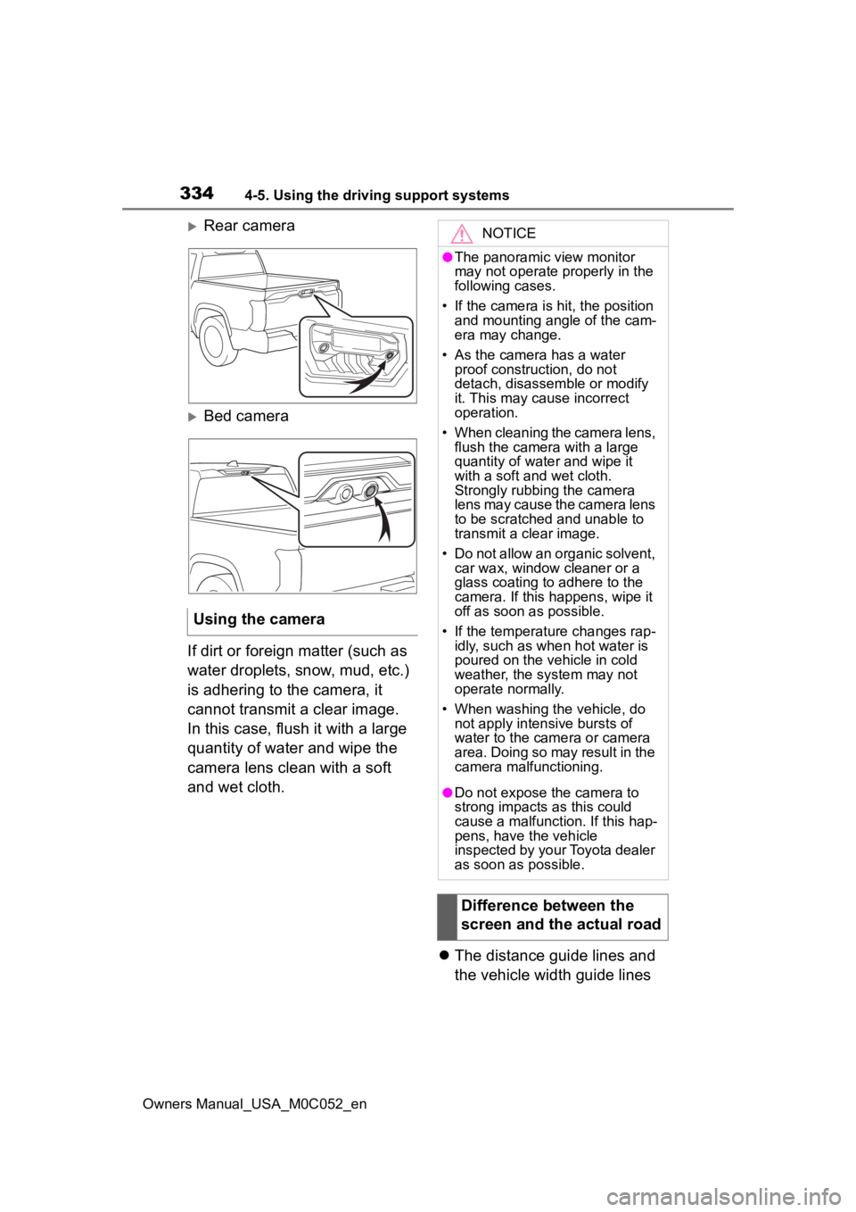
Rear camera
Bed camera
If dirt or foreign matter (such as
water droplets, snow, mud, etc.)
is adhering to the camera, it
cannot transmit a clear image.
In this case, flush it with a large
quantity of water and wipe the
camera lens clean with a soft
and wet cloth. The distance guide lines and
the vehicle width guide lines
Using the camera
NOTICE
●The panoramic view monitor
may not operate properly in the
following cases.
• If the camera is hit, the position and mounting angle of the cam-
era may change.
• As the camera has a water proof construction, do not
detach, disassemble or modify
it. This may cause incorrect
operation.
• When cleaning the camera lens, flush the camera with a large
quantity of water and wipe it
with a soft and wet cloth.
Strongly rubbing the camera
lens may cause the camera lens
to be scratched and unable to
transmit a clear image.
• Do not allow an organic solvent, car wax, window cleaner or a
glass coating to adhere to the
camera. If this happens, wipe it
off as soon as possible.
• If the temperature changes rap- idly, such as when hot water is
poured on the vehicle in cold
weather, the system may not
operate normally.
• When washing the vehicle, do not apply intensive bursts of
water to the came ra or camera
area. Doing so may result in the
camera malfunctioning.
●Do not expose the camera to
strong impacts as this could
cause a malfunction. If this hap-
pens, have the vehicle
inspected by your Toyota dealer
as soon as possible.
Difference between the
screen and the actual road
Page 335 of 618
3354-5. Using the driving support systems
Owners Manual_USA_M0C052_en
4
Driving
may not actually be parallel
with the dividing lines of the
parking space, even when
they appear to be so. Be sure
to check visually.
The distances between the
vehicle width guide lines and
the left and right dividing lines
of the parking space may not
be equal, even when they
appear to be so. Be sure to
check visually.
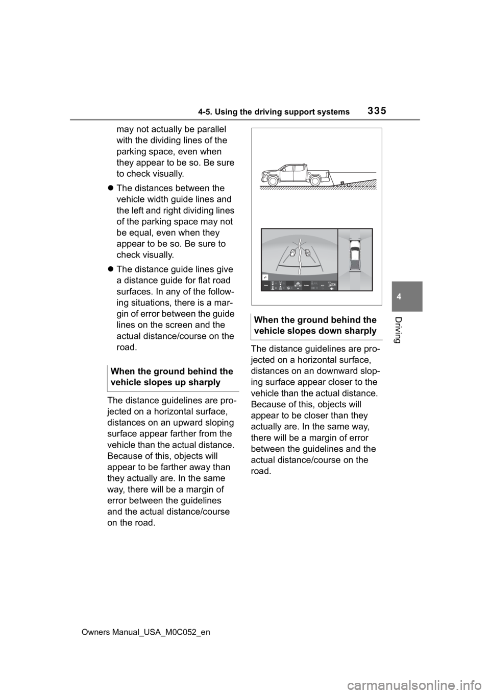
The distance guide lines give
a distance guide for flat road
surfaces. In any of the follow-
ing situations, there is a mar-
gin of error between the guide
lines on the screen and the
actual distance/course on the
road.
The distance guidelines are pro-
jected on a horizontal surface,
distances on an upward sloping
surface appear farther from the
vehicle than the actual distance.
Because of this , objects will
appear to be farther away than
they actually are. In the same
way, there will be a margin of
error between the guidelines
and the actual distance/course
on the road. The distance guidelines are pro-
jected on a horizontal surface,
distances on an downward slop-
ing surface appear closer to the
vehicle than the actual distance.
Because of this, objects will
appear to be closer than they
actually are. In the same way,
there will be a margin of error
between the guidelines and the
actual distance/course on the
road.
When the ground behind the
vehicle slopes up sharply
When the ground behind the
vehicle slopes down sharply
Page 347 of 618
3474-5. Using the driving support systems
Owners Manual_USA_M0C052_en
4
Driving
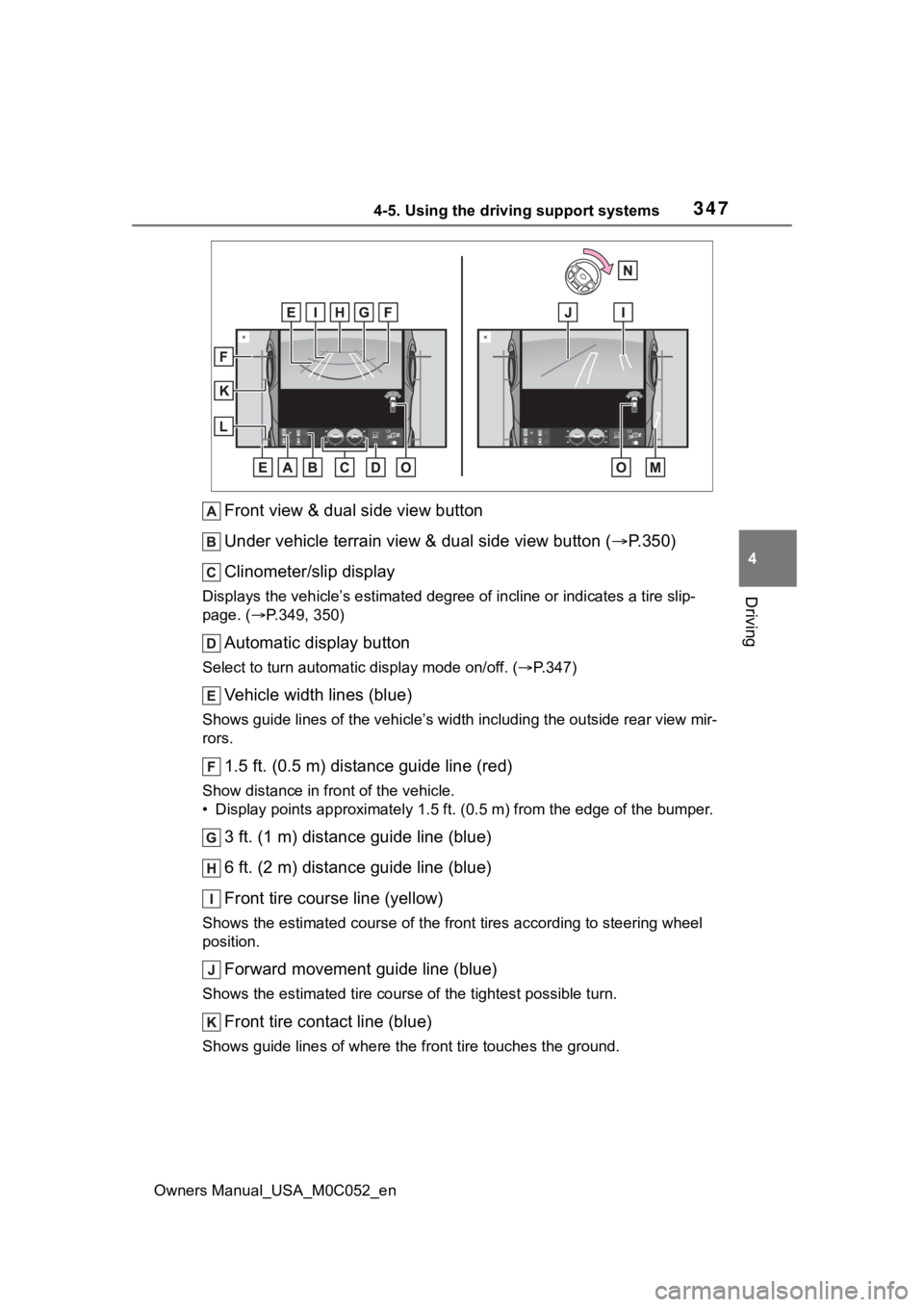
Front view & dual side view button
Under vehicle terrain view & dual side view button ( P.350)
Clinometer/slip display
Displays the vehicle’s estimate d degree of incline or indicates a tire slip-
page. ( P.349, 350)
Automatic display button
Select to turn automatic display mode on/off. (P.347)
Vehicle width lines (blue)
Shows guide lines of the vehicle’ s width including the outside rear view mir-
rors.
1.5 ft. (0.5 m) distance guide line (red)
Show distance in front of the vehicle.
• Display points approximately 1 .5 ft. (0.5 m) from the edge of the bumper.
3 ft. (1 m) distance guide line (blue)
6 ft. (2 m) distance guide line (blue)
Front tire course line (yellow)
Shows the estimated course of the front tires according to steering wheel
position.
Forward movement guide line (blue)
Shows the estimated tire cours e of the tightest possible turn.
Front tire contact line (blue)
Shows guide lines of where the f ront tire touches the ground.
Page 351 of 618

3514-5. Using the driving support systems
Owners Manual_USA_M0C052_en
4
Driving
Show distance in front of the vehicle.
• Display points approximately 1.5 ft. (0.5 m) fr om the edge of the bumper.
Front tire contact line (blue)
Shows guide lines of where the f ront tire touches the ground.
Vehicle width lines (blue)
Shows guide lines of the vehicle’ s width including the outside rear view mir-
rors.
Rear tire contact line (blue)
Shows guide lines of where the rear tire touches the ground.
Intuitive parking assist
When a sensor detects an obstacle, the direction of and the app roximate
distance to the obsta cle are displayed and the buzzer sounds.
●The screen can be displayed when the shift lever is in a positi on other
than R.
●While the under vehicle terrain view is displayed, if the vehicle speed
reaches or exceeds approximately 3 mph (5 km/h), the screen automati-
cally returns to the front view display.
●In the following situations, the under vehicle terrain view sel ection button
cannot be operated.
• The vehicle is not completely stopped
• After the hybrid system starts, a fixed distance or more has not been
driven
• After the front-wheel drive cont rol switch is shifted to “4L”, a fixed distance
or more has not been driven
●In the following situations, the system may not operate normall y, or it may
not be possible to switch to the under vehicle terrain view.
• The road is covered with snow
• It is nighttime and the road has no illumination
• Dirt or foreign matter is adhering to the camera lens
• There is water in front of the vehicle (a river, puddle, sea water, etc.)
WARNING
●The tire position indicator lines and vehicle pos ition indicator lines may
differ from actual vehicle positions depending on the number of passen-
gers, cargo weight, road grade, r oad surface conditions, brightness of
the surrounding environment, etc. Always drive the vehicle whil e con-
firming the safety of your surroundings.
●The image displayed is one that was previously taken at a point approx-
imately 32 ft. (10m) behind the current vehicle position. In cases such
as when objects move after the im age is taken, the image displayed on
the screen may differ from the actual state.
Page 352 of 618
3524-5. Using the driving support systems
Owners Manual_USA_M0C052_en
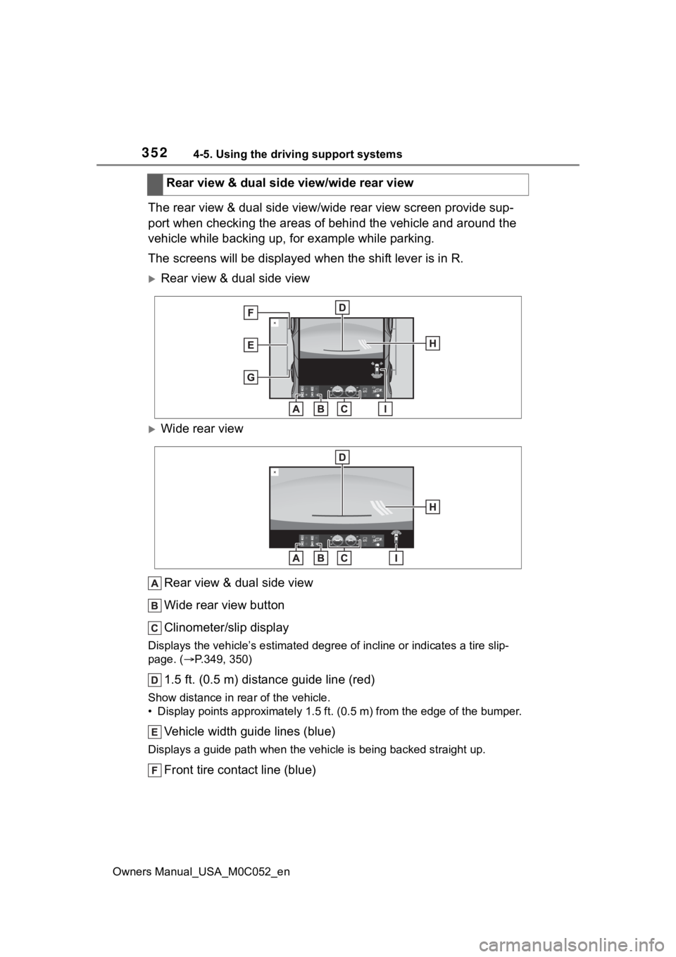
The rear view & dual side view/wide rear view screen provide sup-
port when checking the areas of behind the vehicle and around t he
vehicle while backing up, for example while parking.
The screens will be displayed when the shift lever is in R.
Rear view & dual side view
Wide rear view
Rear view & dual side view
Wide rear view button
Clinometer/slip display
Displays the vehicle’s estimate d degree of incline or indicates a tire slip-
page. ( P.349, 350)
1.5 ft. (0.5 m) distance guide line (red)
Show distance in rear of the vehicle.
• Display points approximately 1 .5 ft. (0.5 m) from the edge of the bumper.
Vehicle width guide lines (blue)
Displays a guide path w hen the vehicle is being backed straight up.
Front tire contact line (blue)Rear view & dual side view/wide rear view
Page 417 of 618
4195-3. Using the storage features
Owners Manual_USA_M0C052_en
5
Interior features
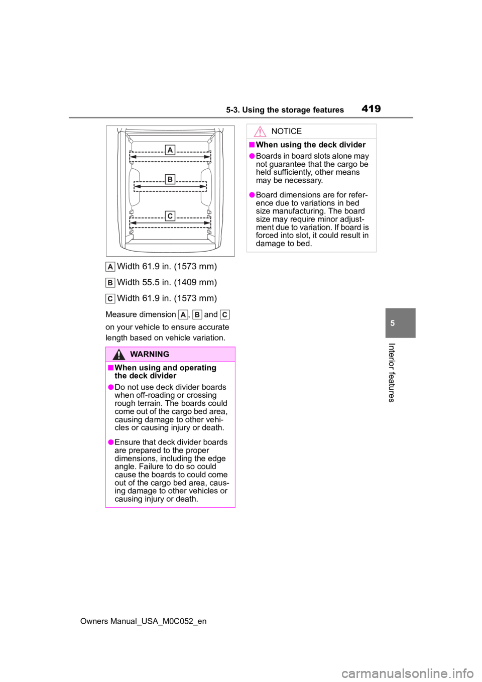
Width 61.9 in. (1573 mm)
Width 55.5 in. (1409 mm)
Width 61.9 in. (1573 mm)
Measure dimension , and
on your vehicle to ensure accurate
length based on v ehicle variation.
WARNING
■When using and operating
the deck divider
●Do not use deck divider boards
when off-roading or crossing
rough terrain. The boards could
come out of the cargo bed area,
causing damage to other vehi-
cles or causing injury or death.
●Ensure that deck divider boards
are prepared to the proper
dimensions, including the edge
angle. Failure to do so could
cause the boards to could come
out of the cargo bed area, caus-
ing damage to other vehicles or
causing injury or death.
NOTICE
■When using the deck divider
●Boards in board slots alone may
not guarantee that the cargo be
held sufficiently, other means
may be necessary.
●Board dimensions are for refer-
ence due to variations in bed
size manufacturing. The board
size may require minor adjust-
ment due to variation. If board is
forced into slot, it could result in
damage to bed.
Page 476 of 618
4786-3. Do-it-yourself maintenance
Owners Manual_USA_M0C052_en
When replacing wheels, care
should be taken to ensure that
they are equivalent to those
removed in load capacity, diam-
eter, rim width and inset
*.
Replacement wheels are avail-
able at your Toyota dealer.
*: Conventionally referred to as off- set.
Toyota does not recommend
using the following:
Wheels of different sizes or
types
Used wheels
Bent wheels that have been
straightened
■When replacing wheels
The wheels of your vehicle are
equipped with tire pressure warning
valves and transmitters that allow
the tire pressure warning system to
provide advance warning in the
event of a loss in tire inflation pres-
sure. Whenever wheels are
replaced, the tire pressure warning
valves and transmitters must be
installed. ( P.470)
Wheels
If a wheel is bent, cracked or
heavily corroded, it should
be replaced. Otherwise, the
tire may separate from the
wheel or cause a loss of
handling control.
Wheel selection
WARNING
■When replacing wheels
●Do not use wheels that are a dif-
ferent size from those recom-
mended in the Owner’s Manual
or certification label, as this may
result in a loss of handling con-
trol.
●Never use an inner tube in a
leaking wheel which is designed
for a tubeless tire.
Doing so may result in an acci-
dent, causing death or serious
injury.
■When installing the wheel
nuts
Never use oil or grease on the
wheel bolts or wheel nuts. Oil and
grease may cause the wheel nuts
to be excessively tightened, lead-
ing to bolt or disc wheel damage.
In addition, the oil or grease can
cause the wheel nuts to loosen
and the wheel may fall off, caus-
ing an accident and resulting in
death or serious injury. Remove
any oil or grease from the wheel
bolts or wheel nuts.
■Use of defective wheels pro-
hibited
Do not use cracke d or deformed
wheels. Doing so could cause the
tire to leak air during driving, pos-
sibly causing an accident.
Page 538 of 618
5408-1. Specifications
Owners Manual_USA_M0C052_en
8-1.Specifications
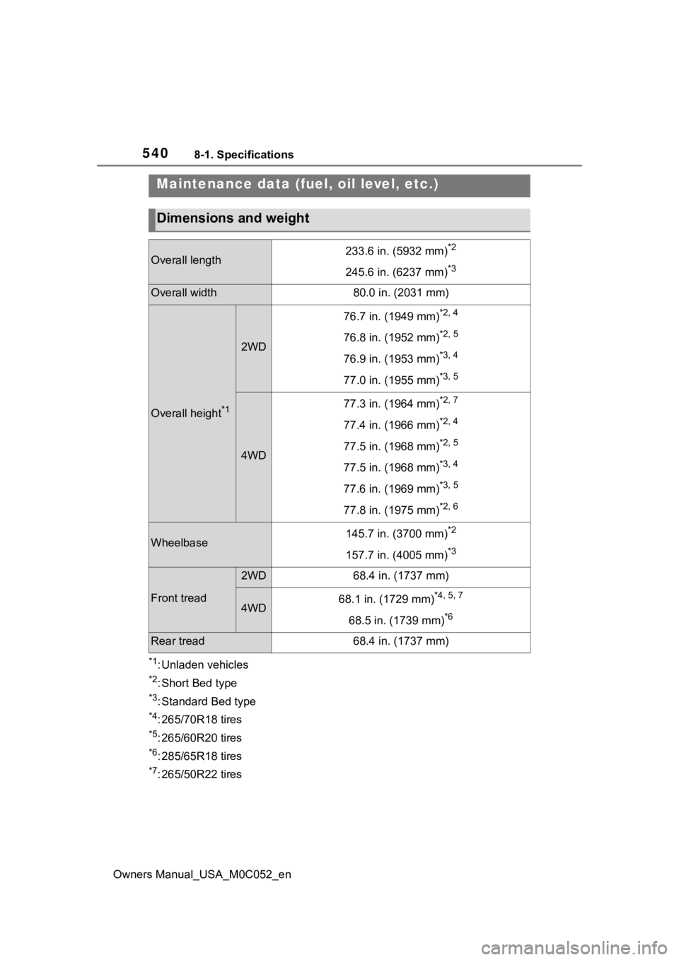
*1: Unladen vehicles
*2: Short Bed type
*3: Standard Bed type
*4: 265/70R18 tires
*5: 265/60R20 tires
*6: 285/65R18 tires
*7: 265/50R22 tires
Maintenance data (fuel, oil level, etc.)
Dimensions and weight
Overall length233.6 in. (5932 mm)*2
245.6 in. (6237 mm)*3
Overall width80.0 in. (2031 mm)
Overall height*1
2WD
76.7 in. (1949 mm)*2, 4
76.8 in. (1952 mm)*2, 5
76.9 in. (1953 mm)*3, 4
77.0 in. (1955 mm)*3, 5
4WD
77.3 in. (1964 mm)*2, 7
77.4 in. (1966 mm)*2, 4
77.5 in. (1968 mm)*2, 5
77.5 in. (1968 mm)*3, 4
77.6 in. (1969 mm)*3, 5
77.8 in. (1975 mm)*2, 6
Wheelbase145.7 in. (3700 mm)*2
157.7 in. (4005 mm)*3
Front tread
2WD68.4 in. (1737 mm)
4WD68.1 in. (1729 mm)*4, 5, 7
68.5 in. (1739 mm)*6
Rear tread68.4 in. (1737 mm)
Page 551 of 618
5538-1. Specifications
Owners Manual_USA_M0C052_en
8
Vehicle specifications
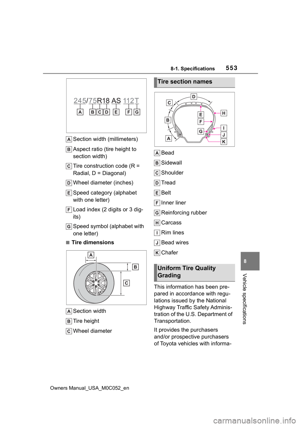
Section width (millimeters)
Aspect ratio (tire height to
section width)
Tire construction code (R =
Radial, D = Diagonal)
Wheel diameter (inches)
Speed category (alphabet
with one letter)
Load index (2 digits or 3 dig-
its)
Speed symbol (alphabet with
one letter)
■Tire dimensions Section width
Tire height
Wheel diameter Bead
Sidewall
Shoulder
Tread
Belt
Inner liner
Reinforcing rubber
Carcass
Rim lines
Bead wires
Chafer
This information has been pre-
pared in accordance with regu-
lations issued by the National
Highway Traffic Safety Adminis-
tration of the U.S. Department of
Transportation.
It provides the purchasers
and/or prospective purchasers
of Toyota vehicles with informa-
Tire section names
Uniform Tire Quality
Grading