tire size TOYOTA VENZA HYBRID 2023 Owners Manual
[x] Cancel search | Manufacturer: TOYOTA, Model Year: 2023, Model line: VENZA HYBRID, Model: TOYOTA VENZA HYBRID 2023Pages: 560, PDF Size: 12.18 MB
Page 15 of 560
15Pictorial index
To prevent freezing (windshield wiper de-icer)*...........P.325, 335
Precautions against car wash
(Rain-sensing windshield wipers)
*.......................................P.373
Replacing the wiper insert .................................... ...............P.421
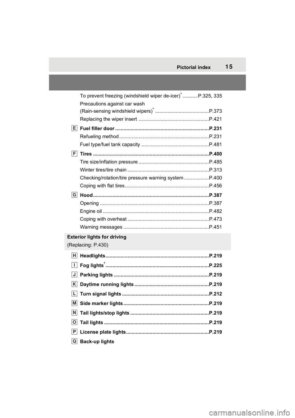
Fuel filler door ............................................... .....................P.231
Refueling method ............................................... ..................P.231
Fuel type/fuel tan k capacity .................................................P.481
Tires ....................................................................................P.400
Tire size/inflation pressure ................................... ................P.485
Winter tires/tire chain ........................................ ...................P.313
Checking/rotation/tire pressur e warning system ..................P.400
Coping with flat tires......................................... ....................P.456
Hood ....................................................................................P.387
Opening ........................................................ .......................P.387
Engine oil ..................................................... ........................P.482
Coping with overheat ........................................... ................P.473
Warning messages ..............................................................P.451
Headlights..................................................... ......................P.219
Fog lights
*............................................................... ............P.225
Parking lights .....................................................................P.219
Daytime running lights .. ....................................................P.219
Turn signal lights ...............................................................P.212
Side marker lights ............................................. .................P.219
Tail lights/stop lights ........................................ .................P.219
Tail lights .................................................... ........................P.219
License plate lights........................................... .................P.219
Back-up lights
Exterior lights for driving
(Replacing: P.430)
E
F
G
H
I
J
K
L
M
N
O
P
Q
Page 106 of 560
1062-1. Instrument cluster
wheel in 6 steps from 0 to 5.
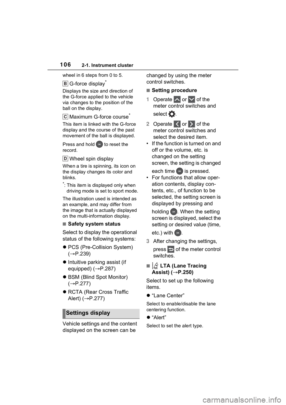
G-force display*
Displays the size and direction of
the G-force applied to the vehicle
via changes to the position of the
ball on the display.
Maximum G-force course*
This item is linke d with the G-force
display and the course of the past
movement of the ball is displayed.
Press and hold to reset the
record.
Wheel spin display
When a tire is spin ning, its icon on
the display change s its color and
blinks.
*: This item is displayed only when driving mode is set to sport mode.
The illustration used is intended as
an example, and may differ from
the image that is actually displayed
on the multi-info rmation display.
■Safety system status
Select to display the operational
status of the following systems:
PCS (Pre-Collision System)
( P.239)
Intuitive parking assist (if
equipped) ( P.287)
BSM (Blind Spot Monitor)
( P.277)
RCTA (Rear Cross Traffic
Alert) ( P.277)
Vehicle settings and the content
displayed on the screen can be changed by using the meter
control switches.
■Setting procedure
1 Operate or of the
meter control switches and
select .
2 Operate or of the
meter control switches and
select the desired item.
• If the function is turned on and off or the volume, etc. is
changed on the setting
screen, the setting is changed
each time is pressed.
• For functions that allow oper- ation contents, display con-
tents, etc., of function to be
selected, the setting screen is
displayed by pressing and
holding . When the setting
screen is displayed, select the
setting or desired value (time,
etc.) with .
3 After changing the settings,
press of the meter control
switches.
■ LTA (Lane Tracing
Assist) ( P.250)
Select to set up the following
items.
“Lane Center”
Select to enable /disable the lane
centering function.
“Alert”
Select to set the alert type.
Settings display
B
C
D
Page 174 of 560
1743-4. Adjusting the steering wheel and mirrors
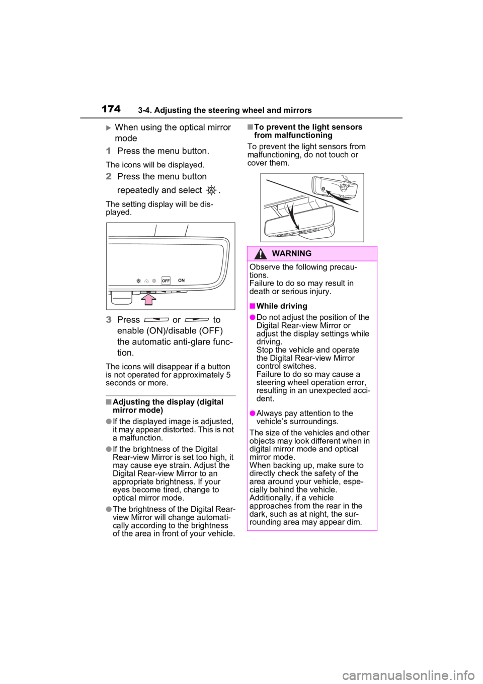
When using the optical mirror
mode
1 Press the menu button.
The icons will be displayed.
2Press the menu button
repeatedly and select .
The setting display will be dis-
played.
3Press or to
enable (ON)/disable (OFF)
the automatic anti-glare func-
tion.
The icons will disappear if a button
is not operated fo r approximately 5
seconds or more.
■Adjusting the display (digital
mirror mode)
●If the displayed image is adjusted,
it may appear distorted. This is not
a malfunction.
●If the brightness of the Digital
Rear-view Mirror is set too high, it
may cause eye strain. Adjust the
Digital Rear-view Mirror to an
appropriate brightness. If your
eyes become tired, change to
optical mirror mode.
●The brightness of the Digital Rear-
view Mirror will ch ange automati-
cally according to the brightness
of the area in front of your vehicle.
■To prevent the light sensors
from malfunctioning
To prevent the light sensors from
malfunctioning, do not touch or
cover them.
WARNING
Observe the following precau-
tions.
Failure to do so may result in
death or serious injury.
■While driving
●Do not adjust the position of the
Digital Rear-view Mirror or
adjust the display settings while
driving.
Stop the vehicle and operate
the Digital Rear-view Mirror
control switches.
Failure to do so may cause a
steering wheel operation error,
resulting in an unexpected acci-
dent.
●Always pay attention to the
vehicle’s surroundings.
The size of the vehicles and other
objects may look different when in
digital mirror mode and optical
mirror mode.
When backing up, make sure to
directly check the safety of the
area around your vehicle, espe-
cially behind the vehicle.
Additionally, if a vehicle
approaches from the rear in the
dark, such as at night, the sur-
rounding area may appear dim.
Page 253 of 560
2534-5. Using the driving support systems
4
Driving
WARNING
●The vehicle is driven in an area
without white (yellow) lines,
such as in front of a tollgate or
checkpoint, or at an intersec-
tion, etc.
●The white (yellow) lines are
cracked, “Botts’ dots”, “Raised
pavement marker” or stones are
present.
●The white (yellow) lines cannot
be seen or are difficult to see
due to sand, etc.
●The vehicle is driven on a road
surface that is wet due to rain,
puddles, etc.
●The traffic lines are yellow
(which may be mo re difficult to
recognize than lines that are
white).
●The white (yellow) lines cross
over a curb, etc.
●The vehicle is driven on a bright
surface, such as concrete.
●If the edge of the road is not
clear or straight.
●The vehicle is driven on a sur-
face that is bright due to
reflected light, etc.
●The vehicle is driven in an area
where the brightness changes
suddenly, such as at the
entrances and exits of tunnels,
etc.
●Light from the h eadlights of an
oncoming vehicle, the sun, etc.
enters the camera.
●The vehicle is driven on a slope.
●The vehicle is driven on a road
which tilts left or right, or a wind-
ing road.
●The vehicle is driven on an
unpaved or rough road.
●The traffic lane is excessively
narrow or wide.
●The vehicle is extremely tilted
due to carrying heavy luggage
or having improper tire pres-
sure.
●The distance to the preceding
vehicle is extremely short.
●The vehicle is moving up and
down a large amount due to
road conditions during driving
(poor roads or road seams).
●When driving in a tunnel or at
night with the headlights off or
when a headlight is dim due to
its lens being dir ty or it being
misaligned.
●The vehicle is struck by a cross-
wind.
●The vehicle is affected by wind
from a vehicle driven in a
nearby lane.
●The vehicle has just changed
lanes or crossed an intersec-
tion.
●Tires which differ by structure,
manufacturer, brand or tread
pattern are used.
●When tires of a size other than
specified are installed.
●Snow tires, etc . are equipped.
●The vehicle is b eing driven at
extremely high speeds.
Page 285 of 560
2854-5. Using the driving support systems
4
Driving
as a towing eyelet, bumper pro-
tector (an additional trim strip,
etc.), bicycle carrier, or snow
plow.
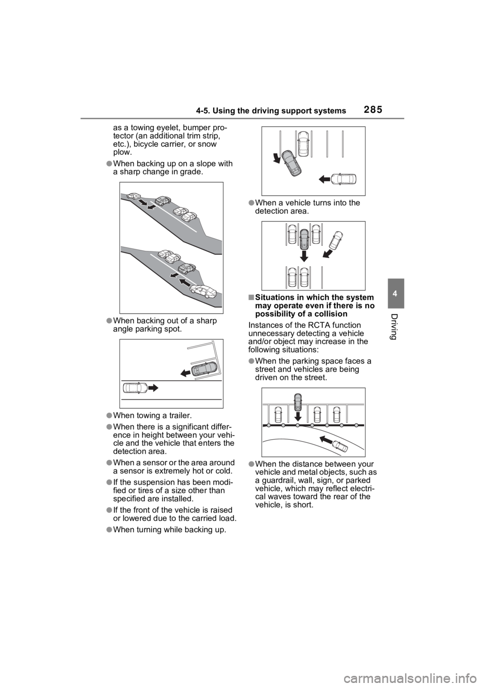
●When backing up on a slope with
a sharp change in grade.
●When backing out of a sharp
angle parking spot.
●When towing a trailer.
●When there is a significant differ-
ence in height between your vehi-
cle and the vehicle that enters the
detection area.
●When a sensor or the area around
a sensor is extremely hot or cold.
●If the suspension has been modi-
fied or tires of a size other than
specified are installed.
●If the front of the vehicle is raised
or lowered due to the carried load.
●When turning while backing up.
●When a vehicle tu rns into the
detection area.
■Situations in which the system
may operate even if there is no
possibility of a collision
Instances of the RCTA function
unnecessary detec ting a vehicle
and/or object may increase in the
following situations:
●When the parking space faces a
street and vehicles are being
driven on the street.
●When the distance between your
vehicle and metal objects, such as
a guardrail, wall, sign, or parked
vehicle, which may reflect electri-
cal waves toward the rear of the
vehicle, is short.
Page 286 of 560
2864-5. Using the driving support systems
●When equipment that may
obstruct a sensor is installed, such
as a towing eyelet, bumper pro-
tector (an additional trim strip,
etc.), bicycle carrier, or snow
plow.
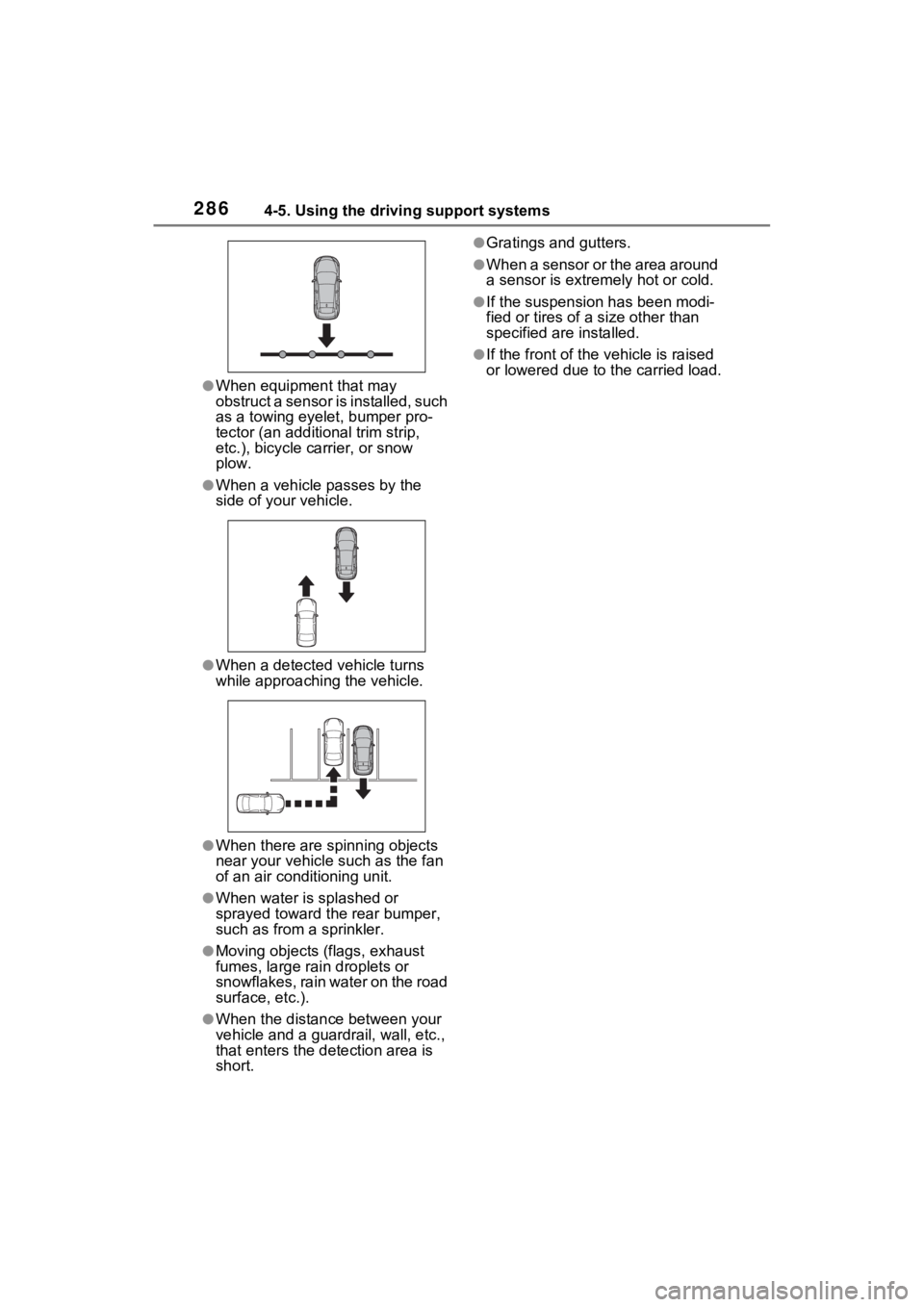
●When a vehicle passes by the
side of your vehicle.
●When a detected vehicle turns
while approaching the vehicle.
●When there are spinning objects
near your vehicle such as the fan
of an air conditioning unit.
●When water is splashed or
sprayed toward t he rear bumper,
such as from a sprinkler.
●Moving objects (flags, exhaust
fumes, large rain droplets or
snowflakes, rain water on the road
surface, etc.).
●When the distanc e between your
vehicle and a guardr ail, wall, etc.,
that enters the detection area is
short.
●Gratings and gutters.
●When a sensor or the area around
a sensor is extremely hot or cold.
●If the suspension has been modi-
fied or tires of a size other than
specified are installed.
●If the front of the v ehicle is raised
or lowered due to the carried load.
Page 296 of 560
2964-5. Using the driving support systems
The Parking Support Brake can
be enabled/disabled on the
screen of the multi-information
display. All of the Parking Sup-
port Brake functions (static
objects and rear-crossing vehi-
cles) are enabled/disabled
simultaneously. (P.106, 117)
When the Parking Support Brake is
disabled, the PKSB OFF indicator
( P.88) illuminates on the multi-
information display.
To re-enable the system, select
on the multi-information display,
select and turn it on.
If the system is disabled, it will
remain off even if the power switch
is turned to ON after the power
switch has been turned to OFF.
WARNING
●When inspecting the vehicle
using a chassis roller, chassis
dynamo or free roller
●When loading the vehicle onto a
boat, truck or other transport
vessel
●If the suspension has been
modified or tires of a size other
than specified are installed
●If the front of the vehicle is
raised or lowered due to the
carried load
●When equipment that may
obstruct a sensor is installed,
such as a towing eyelet, bumper
protector (an additional trim
strip, etc.), bicycle carrier, or
snow plow
●When using automatic car
washing devices
●If the vehicle cannot be driven in
a stable manner, such as when
the vehicle has been in an acci-
dent or is malfunctioning
●When the vehicle is driven in a
sporty manner or off-road
●When the tires are not properly
inflated
●When the tires are very worn
●When tire chains, a compact
spare tire or an emergency tire
puncture repair kit are used.
●During emergency towing
NOTICE
■If “PKSB Unavailable” is dis-
played on the multi-informa-
tion display and the PKSB
OFF indicator illuminates
If this message is displayed
immediately after the power
switch is changed to ON, operate
the vehicle carefully, paying atten-
tion to your surroundings. It may
be necessary to drive the vehicle
for a certain amount of time
before the system returns to nor-
mal. (If the system does not return
to normal after dr iving for a while,
clean the sensors and their sur-
rounding area on the bumpers.)
Enabling/Disabling the
Parking Support Brake
Page 310 of 560
3104-5. Using the driving support systems
WARNING
●Unlike the parking brake, hill-
start assist control is not
intended to hold the vehicle sta-
tionary for an extended period
of time. Do not attempt to use
hill-start assist control to hold
the vehicle on an incline, as
doing so may lead to an acci-
dent.
■When the TRAC/ABS/VSC is
activated
The slip indicator light flashes.
Always drive carefully. Reckless
driving may cause an accident.
Exercise particular care when the
indicator light flashes.
■When the TRAC/VSC systems
are turned off
Be especially careful and drive at
a speed appropriate to the road
conditions. As these are the sys-
tems to help ensure vehicle stabil-
ity and driving force, do not turn
the TRAC/VSC systems off
unless necessary.
■Replacing tires
Make sure that all tires are of the
specified size, brand, tread pat-
tern and total load capacity. In
addition, make sure that the tires
are inflated to the recommended
tire inflation pressure level.
The ABS, TRAC and VSC sys-
tems will not f unction correctly if
different tires are installed on the
vehicle.
Contact your Toyota dealer for
further information when replacing
tires or wheels.
■Handling of tires and the sus-
pension
Using tires with any kind of prob-
lem or modifying the suspension
will affect the driving assist sys-
tems, and may cause a system to
malfunction.
■Secondary Collision Brake
Do not rely solely upon the Sec-
ondary Collision Brake. This sys-
tem is designed to help reduce
the possibility of further damage
due to a secondary collision, how-
ever, that effect changes accord-
ing to various conditions. Overly
relying on the system may result
in death or serious injury.
Page 313 of 560
3134-6. Driving tips
4
Driving
Use fluids that are appropriate
to the prevailing outside tem-
peratures.
• Engine oil
• Engine coolant
• Power control unit coolant
• Washer fluid
Have a service technician
inspect the condition of the
12-volt battery.
Have the vehicle fitted with
four snow tires or purchase a
set of tire chains for the front
tires.
Ensure that all tires are the same
size and brand, and that chains
match the size of the tires.
Winter driving tips
Carry out the necessary
preparations and inspec-
tions before driving the
vehicle in winter. Always
drive the vehicle in a man-
ner appropriate to the pre-
vailing weather conditions.
Preparation for winter
WARNING
■Driving with snow tires
Observe the following precautions
to reduce the risk of accidents.
Failure to do so m ay result in a
loss of vehicle control and cause
death or serious injury.
●Use tires of the specified size.
●Maintain the recommended
level of air pressure.
●Do not drive in excess of 75
mph (120 km/h), regardless of
the type of snow tires being
used.
●Use snow tires on all, not just
some wheels.
■Driving with tire chains
Observe the following precautions
to reduce the risk of accidents.
Failure to do so may result in the
vehicle being unable to be driven
safely, and may cause death or
serious injury.
●Do not drive in excess of the
speed limit specifi ed for the tire
chains being used, or 30 mph
(50 km/h), whichever is lower.
●Avoid driving on bumpy road
surfaces or over potholes.
●Avoid sudden acceleration,
abrupt steering, sudden brak-
ing and shifting operations that
cause sudden engine braking.
●Slow down sufficiently before
entering a curve to ensure that
vehicle control is maintained.
●Do not use LTA (Lane Tracing
Assist) system.
NOTICE
■Repairing or replacing snow
tires
Request repairs or replacement of
snow tires from your Toyota
dealer or legitimate tire retailers.
This is because the removal and
attachment of snow tires affects
the operation of the tire pressure
warning valves and transmitters.
Page 315 of 560
3154-6. Driving tips
4
Driving
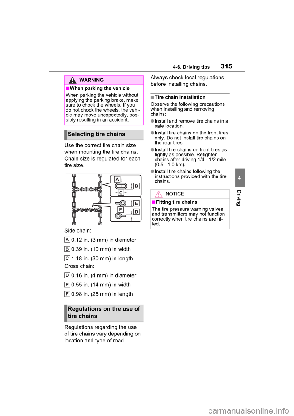
Use the correct tire chain size
when mounting the tire chains.
Chain size is regulated for each
tire size.
Side chain:0.12 in. (3 mm) in diameter
0.39 in. (10 mm) in width
1.18 in. (30 mm) in length
Cross chain:
0.16 in. (4 mm) in diameter
0.55 in. (14 mm) in width
0.98 in. (25 mm) in length
Regulations regarding the use
of tire chains vary depending on
location and type of road. Always check local regulations
before installing chains.
■Tire chain installation
Observe the followi ng precautions
when installing and removing
chains:
●Install and remove tire chains in a
safe location.
●Install tire chains on the front tires
only. Do not install tire chains on
the rear tires.
●Install tire chains on front tires as
tightly as possible. Retighten
chains after drivi ng 1/4 - 1/2 mile
(0.5 - 1.0 km).
●Install tire chains following the
instructions provided with the tire
chains.
WARNING
■When parking the vehicle
When parking the v ehicle without
applying the parking brake, make
sure to chock the wheels. If you
do not chock the wheels, the vehi-
cle may move unexpectedly, pos-
sibly resulting in an accident.
Selecting tire chains
Regulations on the use of
tire chains
A
B
C
D
E
F
NOTICE
■Fitting tire chains
The tire pressure warning valves
and transmitters may not function
correctly when tire chains are fit-
ted.