remote control TOYOTA VERSO S 2011 Owners Manual
[x] Cancel search | Manufacturer: TOYOTA, Model Year: 2011, Model line: VERSO S, Model: TOYOTA VERSO S 2011Pages: 664, PDF Size: 160.56 MB
Page 18 of 664
18Pictorial index
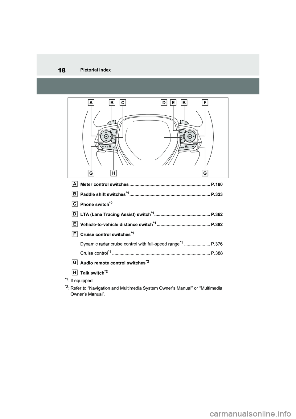
Meter control switches ................................................................. P.180
Paddle shift switches
*1................................................................. P.323
Phone switch
*2
LTA (Lane Tracing Assist) switch*1............................................. P.362
Vehicle-to-vehicle distance switch
*1........................................... P.382
Cruise control switches
*1
Dynamic radar cruise control with full-speed range*1..................... P.376
Cruise control
*1............................................................................... P.388
Audio remote control switches
*2
Talk switch*2
*1
: If equipped
*2: Refer to “Navigation and Multimedia System Owner’s Manual” or “Multimedia
Owner’s Manual”.
A
B
C
D
E
F
G
H
Page 26 of 664
26Pictorial index
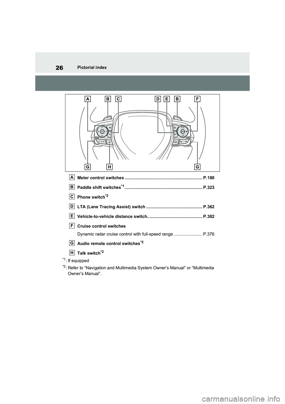
Meter control switches ................................................................. P.180
Paddle shift switches
*1................................................................. P.323
Phone switch
*2
LTA (Lane Tracing Assist) switch ............................................... P.362
Vehicle-to-vehicle distance switch.............................................. P.382
Cruise control switches
Dynamic radar cruise control with full-speed range ........................ P.376
Audio remote control switches
*2
Talk switch*2
*1
: If equipped
*2: Refer to “Navigation and Multimedia System Owner’s Manual” or “Multimedia
Owner’s Manual”.
A
B
C
D
E
F
G
H
Page 77 of 664
77
1
1-4. Theft deterrent system
For safety and security
*: If equipped
■Setting
Turn the power switch to OFF, have
all the passengers exit the vehicle
and ensure that all the doors are
closed.
Using the entry function:
Touch the sensor area on the front
outside door handle twice within 5
seconds.
Using the wireless remote control:
Press twice within 5 sec-
onds.
■Canceling
Using the entry function:
Hold the front outside door handle.
Using the wireless remote control:
Press .
Double locking system*
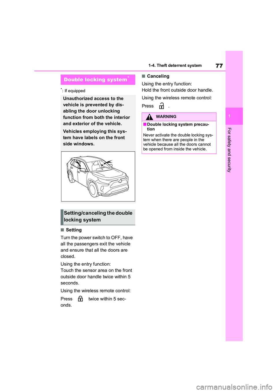
Unauthorized access to the
vehicle is prevented by dis-
abling the door unlocking
function from both the interior
and exterior of the vehicle.
Vehicles employing this sys-
tem have labels on the front
side windows.
Setting/canceling the double
locking system
WARNING
■Double locking system precau- tion
Never activate the double locking sys-
tem when there are people in the vehicle because all the doors cannot be opened from inside the vehicle.
Page 78 of 664
781-4. Theft deterrent system
*: If equipped
■Items to check before locking
the vehicle
To prevent unexpected triggering of
the alarm and vehicle theft, make
sure of the following:
Nobody is in the vehicle.
The side windows and pan-
oramic moon roof (if equipped)
are closed before the alarm is
set.
No valuables or other personal
items are left in the vehicle.
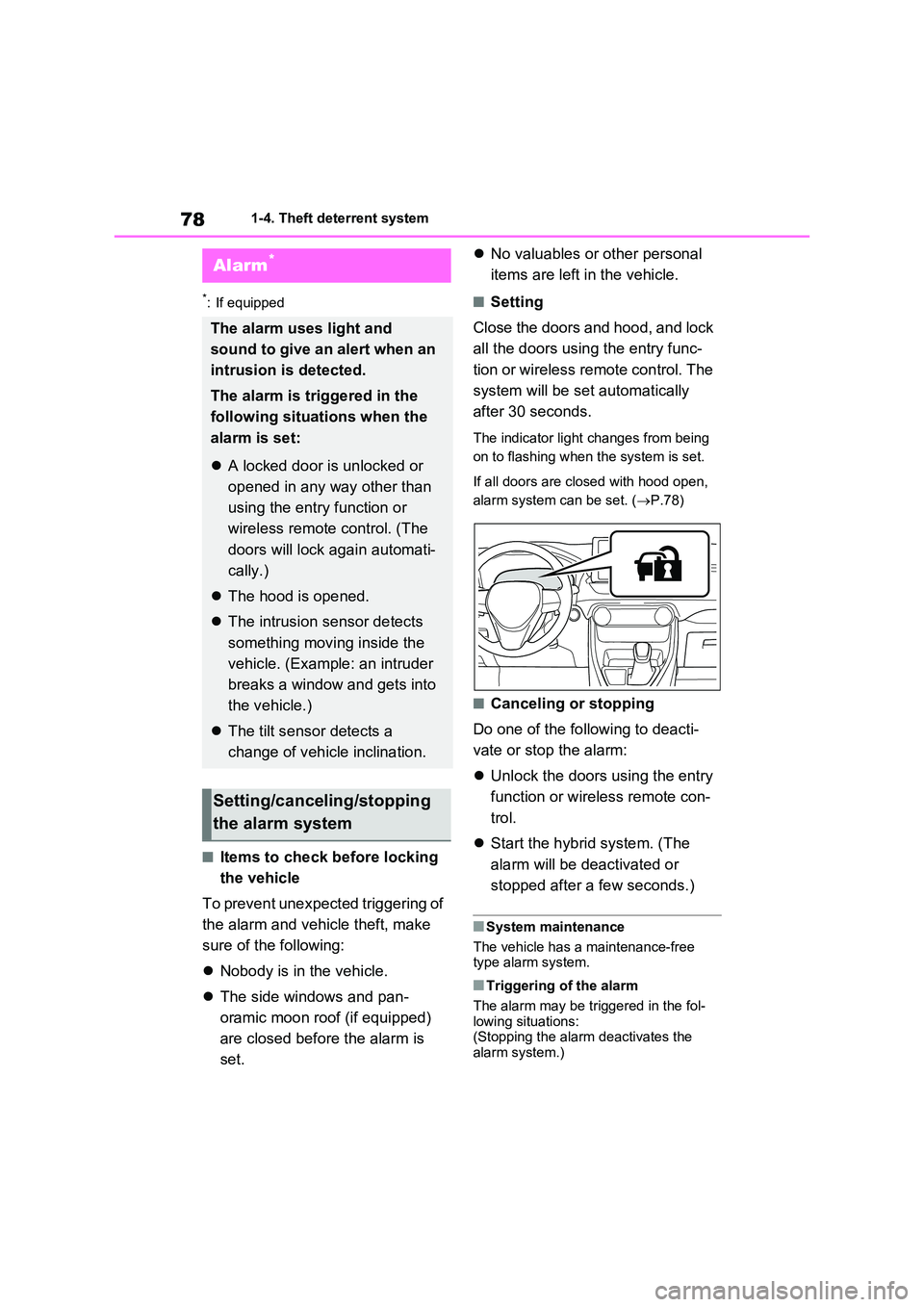
■Setting
Close the doors and hood, and lock
all the doors using the entry func-
tion or wireless remote control. The
system will be set automatically
after 30 seconds.
The indicator light changes from being
on to flashing when the system is set.
If all doors are closed with hood open,
alarm system can be set. ( P.78)
■Canceling or stopping
Do one of the following to deacti-
vate or stop the alarm:
Unlock the doors using the entry
function or wireless remote con-
trol.
Start the hybrid system. (The
alarm will be deactivated or
stopped after a few seconds.)
■System maintenance
The vehicle has a maintenance-free type alarm system.
■Triggering of the alarm
The alarm may be triggered in the fol- lowing situations:(Stopping the alarm deactivates the
alarm system.)
Alarm*
The alarm uses light and
sound to give an alert when an
intrusion is detected.
The alarm is triggered in the
following situations when the
alarm is set:
A locked door is unlocked or
opened in any way other than
using the entry function or
wireless remote control. (The
doors will lock again automati-
cally.)
The hood is opened.
The intrusion sensor detects
something moving inside the
vehicle. (Example: an intruder
breaks a window and gets into
the vehicle.)
The tilt sensor detects a
change of vehicle inclination.
Setting/canceling/stopping
the alarm system
Page 80 of 664
801-4. Theft deterrent system
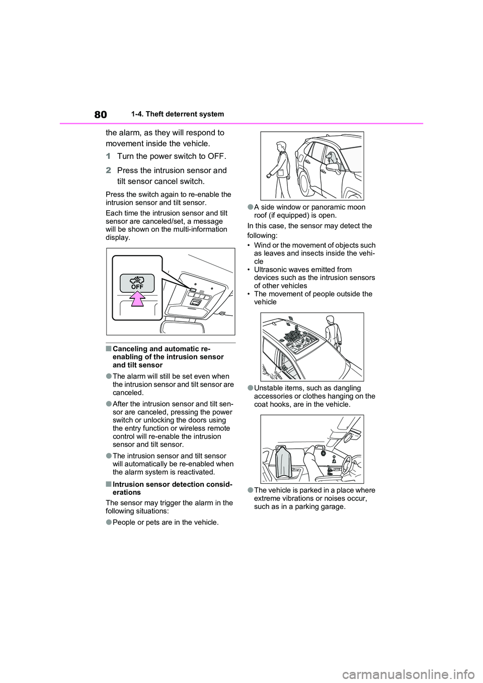
the alarm, as they will respond to
movement inside the vehicle.
1 Turn the power switch to OFF.
2 Press the intrusion sensor and
tilt sensor cancel switch.
Press the switch again to re-enable the intrusion sensor and tilt sensor.
Each time the intrusion sensor and tilt
sensor are canceled/set, a message will be shown on the multi-information display.
■Canceling and automatic re-enabling of the intrusion sensor
and tilt sensor
●The alarm will still be set even when
the intrusion sensor and tilt sensor are canceled.
●After the intrusion sensor and tilt sen-sor are canceled, pressing the power switch or unlocking the doors using
the entry function or wireless remote control will re-enable the intrusion sensor and tilt sensor.
●The intrusion sensor and tilt sensor will automatically be re-enabled when
the alarm system is reactivated.
■Intrusion sensor detection consid- erations
The sensor may trigger the alarm in the
following situations:
●People or pets are in the vehicle.
●A side window or panoramic moon
roof (if equipped) is open.
In this case, the sensor may detect the
following:
• Wind or the movement of objects such as leaves and insects inside the vehi-
cle • Ultrasonic waves emitted from devices such as the intrusion sensors
of other vehicles • The movement of people outside the vehicle
●Unstable items, such as dangling accessories or clothes hanging on the
coat hooks, are in the vehicle.
●The vehicle is parked in a place where
extreme vibrations or noises occur, such as in a parking garage.
Page 121 of 664
121
2 2-2. Charging
Plug-in hybrid system
■Unlocking the charging port
lid
1Unlock the doors using the
smart entry & start system or
wireless remote control.
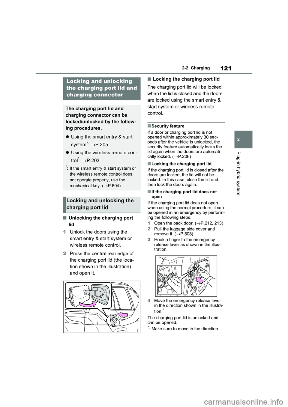
2Press the central rear edge of
the charging port lid (the loca-
tion shown in the illustration)
and open it.
■Locking the charging port lid
The charging port lid will be locked
when the lid is closed and the doors
are locked using the smart entry &
start system or wireless remote
control.
■Security feature
If a door or charging port lid is not
opened within approximately 30 sec-
onds after the vehicle is unlocked, the
security feature automatically locks the
lid again when the doors are automati-
cally locked. (P.206)
■Locking the charging port lid
If the charging port lid is closed after the
doors are locked, the lid will not be
locked. In this case, close the lid and
then lock the doors again.
■If the charging port lid does not
open
If the charging port lid does not open
when using the normal procedure, it can
be opened in an emergency by perform-
ing the following steps.
1Open the back door. (P.212, 213)
2Pull the luggage side cover and
remove it. (P.508)
3Hook a finger to the emergency
release lever as shown in the illus-
tration.
4Move the emergency release lever
in the direction shown in the illustra-
tion.
*
The charging port lid is unlocked and
can be opened.
*: Make sure to move in the direction
Locking and unlocking
the charging port lid and
charging connector
The charging port lid and
charging connector can be
locked/unlocked by the follow-
ing procedures.
Using the smart entry & start
system
*: P.205
Using the wireless remote con-
trol
*: P.203
*: If the smart entry & start system or
the wireless remote control does
not operate properly, use the
mechanical key. (P.604)
Locking and unlocking the
charging port lid
Page 122 of 664
1222-2. Charging
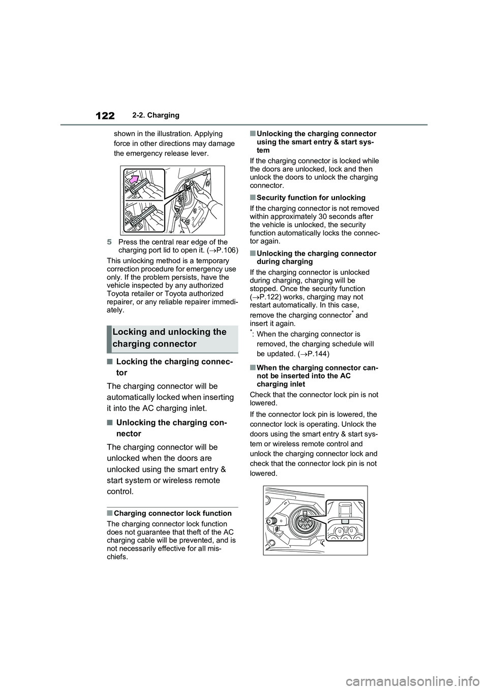
shown in the illustration. Applying
force in other directions may damage
the emergency release lever.
5Press the central rear edge of the
charging port lid to open it. (P.106)
This unlocking method is a temporary
correction procedure for emergency use
only. If the problem persists, have the
vehicle inspected by any authorized
Toyota retailer or Toyota authorized
repairer, or any reliable repairer immedi-
ately.
■Locking the charging connec-
tor
The charging connector will be
automatically locked when inserting
it into the AC charging inlet.
■Unlocking the charging con-
nector
The charging connector will be
unlocked when the doors are
unlocked using the smart entry &
start system or wireless remote
control.
■Charging connector lock function
The charging connector lock function
does not guarantee that theft of the AC
charging cable will be prevented, and is
not necessarily effective for all mis-
chiefs.
■Unlocking the charging connector
using the smart entry & start sys-
tem
If the charging connector is locked while
the doors are unlocked, lock and then
unlock the doors to unlock the charging
connector.
■Security function for unlocking
If the charging connector is not removed
within approximately 30 seconds after
the vehicle is unlocked, the security
function automatically locks the connec-
tor again.
■Unlocking the charging connector
during charging
If the charging connector is unlocked
during charging, charging will be
stopped. Once the security function
(P.122) works, charging may not
restart automatically. In this case,
remove the charging connector
* and
insert it again.
*: When the charging connector is
removed, the charging schedule will
be updated. (P.144)
■When the charging connector can-
not be inserted into the AC
charging inlet
Check that the connector lock pin is not
lowered.
If the connector lock pin is lowered, the
connector lock is operating. Unlock the
doors using the smart entry & start sys-
tem or wireless remote control and
unlock the charging connector lock and
check that the connector lock pin is not
lowered.
Locking and unlocking the
charging connector
Page 125 of 664
125
2
2-2. Charging
Plug-in hybrid system
equipped with a Residual Cur-
rent Circuit-Breaker (RCCB). If it
is not, have one installed by a
duly qualified professional.
When charging outdoors, make
sure to connect to a rain-tight
socket that is certified for outdoor
use. Checking Residual Current
Circuit-Breaker (RCCB) opera-
tion before its use is recom-
mended.
Check whether there are any
local EV-charging regulations in
place, and adhere to them.
*: For detailed information, consult an
electrician.
■The charging environment
For safe charging, the following charging equipment and settings are
recommended.
●Rain-tight socket
When charging outdoors, connect the
plug to a rain-tight socket, and ensure
that the plug remains waterproof while
the plug is connected.
●Dedicated circuit
• To reduce the risk of fire, connect only to an at least 13A branch circuit with an over-current protection.
• To reduce the risk of electric shock when working with the plug, connect to a socket that has a Residual Cur-
rent Circuit-Breaker (RCCB) installed.
●Remote switch
Allows the electricity from the socket to
be interrupted by operating a switch,
thus allowing safe removal and insertion
of the plug on rainy days.
■When your circuit breaker trips
during charging
The upper limit of the charging current
can be changed in “Vehicle Settings” on
the multi-information display.
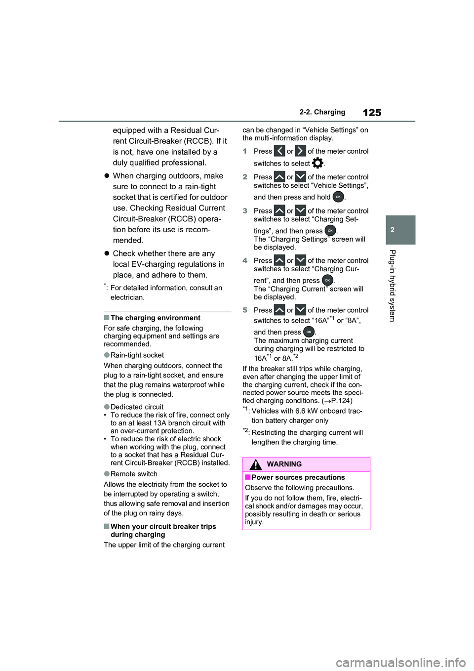
1 Press or of the meter control
switches to select .
2 Press or of the meter control
switches to select “Vehicle Settings”,
and then press and hold .
3 Press or of the meter control
switches to select “Charging Set-
tings”, and then press .
The “Charging Settings” screen will
be displayed.
4 Press or of the meter control
switches to select “Charging Cur-
rent”, and then press .
The “Charging Current” screen will be displayed.
5 Press or of the meter control
switches to select “16A”*1 or “8A”,
and then press .
The maximum charging current
during charging will be restricted to
16A*1 or 8A.*2
If the breaker still trips while charging,
even after changing the upper limit of the charging current, check if the con-nected power source meets the speci-
fied charging conditions. ( P.124)*1: Vehicles with 6.6 kW onboard trac-
tion battery charger only
*2: Restricting the charging current will
lengthen the charging time.
WARNING
■Power sources precautions
Observe the following precautions.
If you do not follow them, fire, electri- cal shock and/or damages may occur,
possibly resulting in death or serious injury.
Page 129 of 664
129
2 2-2. Charging
Plug-in hybrid system
■Hybrid battery (traction bat-
tery) warming control (Green-
land only)
This control operates after the AC
charging cable remains connected
to the vehicle for 3 days and “Bat-
tery Heater” automatically stops. It
automatically insulates the hybrid
battery (traction battery) in
extremely low temperatures.
This control stops 31 days after
the AC charging cable is con-
nected, even if it is still con-
nected to the vehicle.
When this control operates,
charging schedule settings are
ignored and charging starts.
■“Battery Cooler”
When the hybrid battery (traction
battery) is hot and the AC charging
cable is connected to the vehicle,
this function cools the hybrid bat-
tery (traction battery) before
charging is carried out.
“Battery Cooler” will operate when
the “Battery Cooler” of the
“Charging Settings” on the multi-
information display is on. (P.187)
■Traction battery heating and cool-
ing system (“Battery Heater” and
“Battery Cooler”)
●The system operates when the hybrid
battery (traction battery) is below or
above a certain temperature.
●The system may operate when
charging is not being performed.
●When the charging schedule is used
(P.144), this function will operate according to the charging schedule.
■“Battery Heater”
●When “Battery Heater” is operating,
the charging indicator illuminates.
●When the AC charging cable is
removed from the vehicle or remains
connected to the vehicle for approxi-
mately 3 days, the system automati-
cally stops.
●When “Battery Heater” is operating
during charging, the charging time
may be longer than normal.
●If the outside temperature becomes
high while “Battery Heater” is operat-
ing, charging may complete earlier
than the “Departure” time set.
(P.144)
●When the traction battery is almost
completely charged, “Battery Cooler”
may not be implemented.
●When the following operations are
performed while “Battery Heater” is
operating, the hybrid battery (traction
battery) heating operation stops.
• The shift lever is changed to any posi-
tion other than P
• The Remote Air Conditioning System
is operated (P.460)
●“Battery Heater” may operate even
when the hybrid battery (traction bat-
tery) is fully charged depending on the
temperature of the hybrid battery
(traction battery).
• The remaining charge of the hybrid
battery (traction battery) decreases
when “Battery Heater” operates. The
charging operation may start again to
charge the hybrid battery (traction bat-
tery).
• “Charging Stopped Due to Pulled
Charging Connector” may be shown
when the charging connector is
removed while recharging. (P.160)
■“Battery Cooler”
●The charging indicator is illuminated
while “Battery Cooler” is on standby or
operating.
●“Battery Cooler” is implemented for a
Page 159 of 664
159
2 2-2. Charging
Plug-in hybrid system
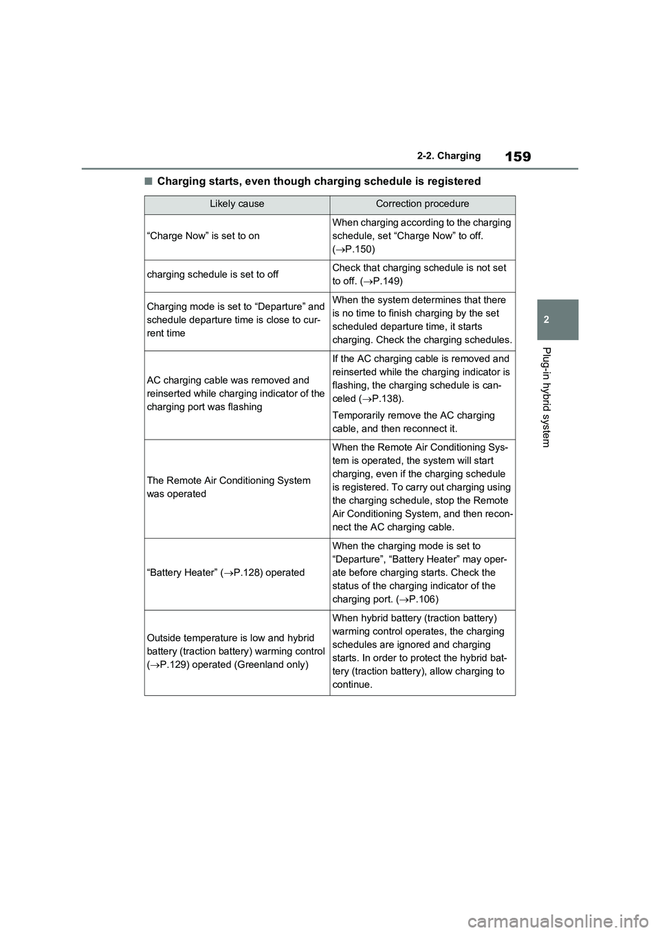
■Charging starts, even though charging schedule is registered
Likely causeCorrection procedure
“Charge Now” is set to on
When charging according to the charging
schedule, set “Charge Now” to off.
(P.150)
charging schedule is set to offCheck that charging schedule is not set
to off. (P.149)
Charging mode is set to “Departure” and
schedule departure time is close to cur-
rent timeWhen the system determines that there
is no time to finish charging by the set
scheduled departure time, it starts
charging. Check the charging schedules.
AC charging cable was removed and
reinserted while charging indicator of the
charging port was flashing
If the AC charging cable is removed and
reinserted while the charging indicator is
flashing, the charging schedule is can-
celed (P.138).
Temporarily remove the AC charging
cable, and then reconnect it.
The Remote Air Conditioning System
was operated
When the Remote Air Conditioning Sys-
tem is operated, the system will start
charging, even if the charging schedule
is registered. To carry out charging using
the charging schedule, stop the Remote
Air Conditioning System, and then recon-
nect the AC charging cable.
“Battery Heater” (P.128) operated
When the charging mode is set to
“Departure”, “Battery Heater” may oper-
ate before charging starts. Check the
status of the charging indicator of the
charging port. (P.106)
Outside temperature is low and hybrid
battery (traction battery) warming control
(P.129) operated (Greenland only)
When hybrid battery (traction battery)
warming control operates, the charging
schedules are ignored and charging
starts. In order to protect the hybrid bat-
tery (traction battery), allow charging to
continue.