brake TOYOTA YARIS HATCHBACK 2012 Workshop Manual
[x] Cancel search | Manufacturer: TOYOTA, Model Year: 2012, Model line: YARIS HATCHBACK, Model: TOYOTA YARIS HATCHBACK 2012Pages: 365, PDF Size: 8.17 MB
Page 306 of 365
328
5-2. Steps to take in an emergency
If the shift lever cannot be shifted from P (vehicles with an automatic transmission)
If the shift lever cannot be shifted with your foot on the brake pedal,
there may be a problem with the shift lock system (a system to pre-
vent accidental operation of the shift lever). Have the vehicle
inspected by your Toyo ta dealer immediately.
The following steps may be used as an emergency measure to
ensure that the shift lever can be shifted:
Set the parking brake.
Turn the engine switch to the “ACC” position.
Depress the brake pedal.
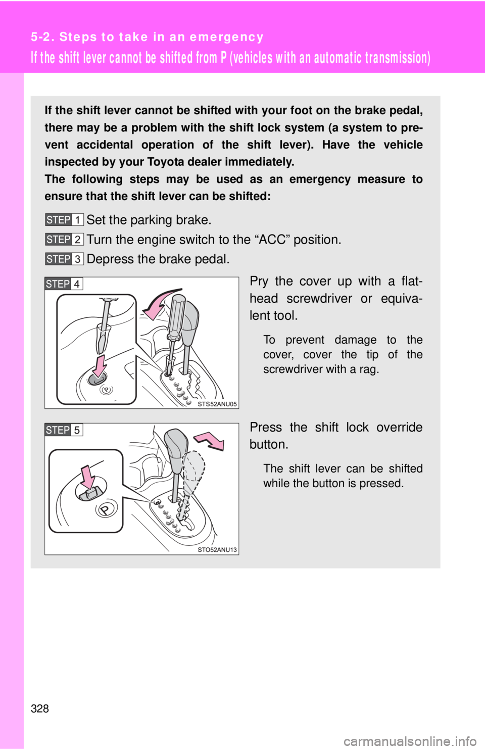
Pry the cover up with a flat-
head screwdriver or equiva-
lent tool.
To prevent damage to the
cover, cover the tip of the
screwdriver with a rag.
Press the shift lock override
button.
The shift lever can be shifted
while the button is pressed.
Page 315 of 365
5
When trouble arises
337
5-2. Steps to take in an emergency
If the vehicle becomes stuck
■Emergency hook Carry out the following procedures if the tires spin or the vehicle
becomes stuck in mud, dirt, or snow:
Stop the engine. Set the parki ng brake and shift the shift
lever to P (vehicles with an automatic transmission) or N
(vehicles with a manual transmission).
Remove the mud, snow or sand from around the stuck tire.
Place wood, stones or some other material under the tires
to help provide traction.
Restart the engine.
Shift the shift lever to the D or R position (vehicles with an
automatic transmission) or 1 or R position (vehicles with a
manual transmission) and carefully apply the accelerator to
free the vehicle.
Turn off TRAC and VSC if these functions are hampering your
attempts to free the vehicle. ( →P. 163)
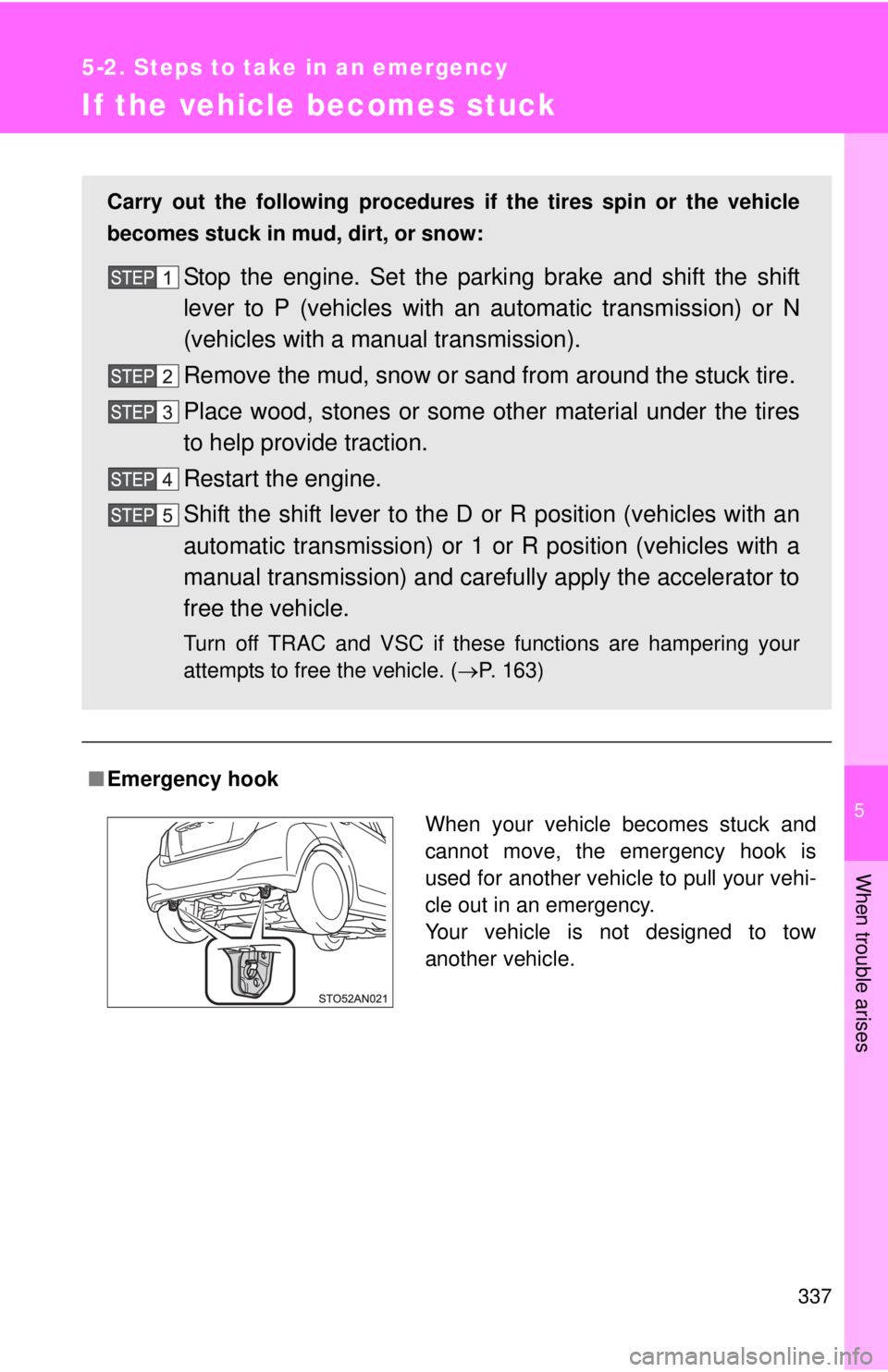
When your vehicle becomes stuck and
cannot move, the emergency hook is
used for another vehicle to pull your vehi-
cle out in an emergency.
Your vehicle is not designed to tow
another vehicle.
Page 317 of 365
5
When trouble arises
339
5-2. Steps to take in an emergency
If your vehicle has to be stopped in an emergency
Only in an emergency, such as if it becomes impossible to stop the
vehicle in the normal way, stop the vehicle using the following pro-
cedure:
Steadily step on the brake pedal with both feet and firmly
depress it.
Do not pump the brake pedal repeatedly as this will increase the
effort required to slow the vehicle.
Shift the shift lever to N.
If the shift lever is shifted to N After slowing down, stop the vehi cle in a safe place by the
road.
Stop the engine.
If the shift lever cannot be shifted to N Keep depressing the brake pedal with both feet to reduce
vehicle speed as much as possible.
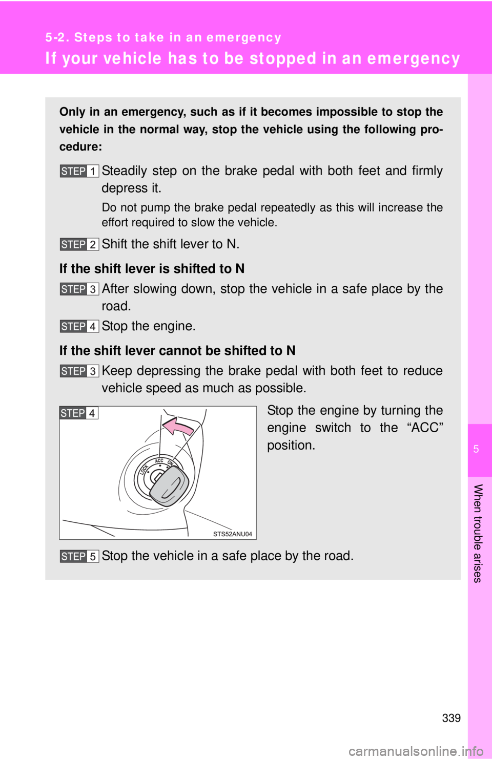
Stop the engine by turning the
engine switch to the “ACC”
position.
Stop the vehicle in a safe place by the road.
Page 318 of 365

340 5-2. Steps to take in an emergency
CAUTION
■If the engine has to be turned off while driving
●Power assist for the brakes and steering wheel will be lost, making the
brake pedal harder to depress and the steering wheel heavier to turn.
Decelerate as much as possible before turning off the engine.
● Never attempt to remove the key, as doing so will lock the steering wheel.
Page 327 of 365
350 6-1. Specifications
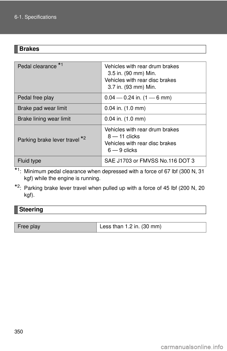
Brakes
*1: Minimum pedal clearance when depressed with a force of 67 lbf (300 N, 31kgf) while the engine is running.
*2: Parking brake lever travel when pulled up with a force of 45 lbf (200 N, 20kgf).
Steering
Pedal clearance *1Vehicles with rear drum brakes 3.5 in. (90 mm) Min.
Vehicles with rear disc brakes 3.7 in. (93 mm) Min.
Pedal free play 0.04 ⎯ 0.24 in. (1 ⎯ 6 mm)
Brake pad wear limit 0.04 in. (1.0 mm)
Brake lining wear limit 0.04 in. (1.0 mm)
Parking brake lever travel *2
Vehicles with rear drum brakes
8 — 11 clicks
Vehicles with rear disc brakes 6 — 9 clicks
Fluid type SAE J1703 or FMVSS No.116 DOT 3
Free playLess than 1.2 in. (30 mm)
Page 339 of 365
362 6-1. Specifications
Warning: The temperature grades of a tire assume that it is properly
inflated and not overloaded.
Excessive speed, underinflation, or excessive loading, either sepa-
rately or in combination, can cause heat buildup and possible tire fail-
ure.
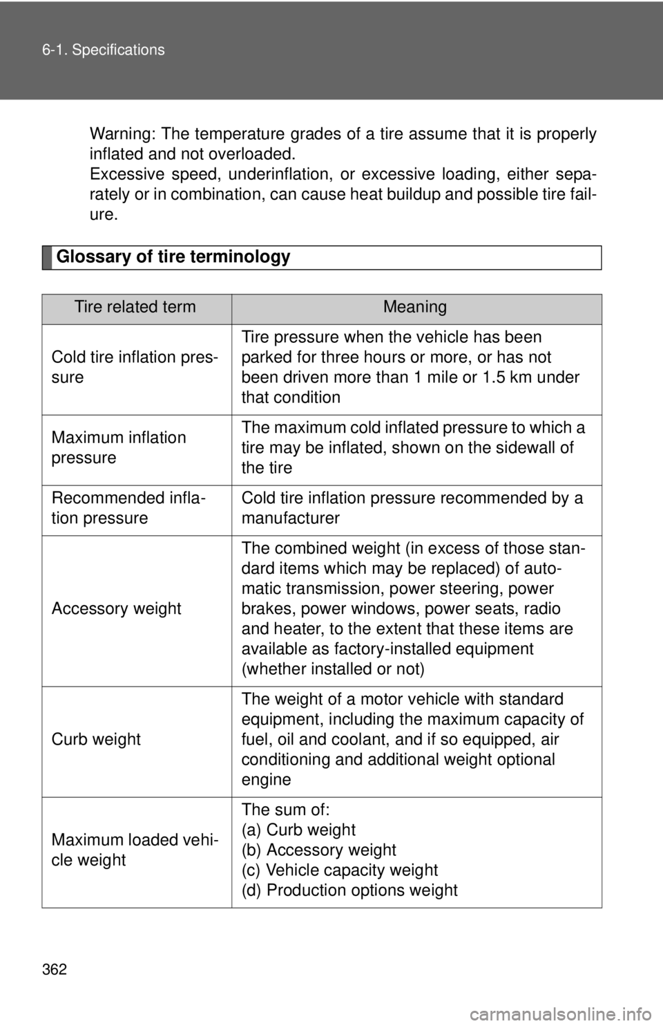
Glossary of tire terminology
Tire related termMeaning
Cold tire inflation pres-
sure
Tire pressure when the vehicle has been
parked for three hours or more, or has not
been driven more than 1 mile or 1.5 km under
that condition
Maximum inflation
pressureThe maximum cold inflated pressure to which a
tire may be inflated, s hown on the sidewall of
the tire
Recommended infla-
tion pressureCold tire inflation pressure recommended by a
manufacturer
Accessory weight
The combined weight (in excess of those stan-
dard items which may be replaced) of auto-
matic transmission, power steering, power
brakes, power windows, power seats, radio
and heater, to the extent that these items are
available as factory-installed equipment
(whether installed or not)
Curb weight
The weight of a motor vehicle with standard
equipment, including the maximum capacity of
fuel, oil and coolant, and if so equipped, air
conditioning and additional weight optional
engine
Maximum loaded vehi-
cle weight
The sum of:
(a) Curb weight
(b) Accessory weight
(c) Vehicle capacity weight
(d) Production options weight
Page 340 of 365
363
6-1. Specifications
6
Vehicle specifications
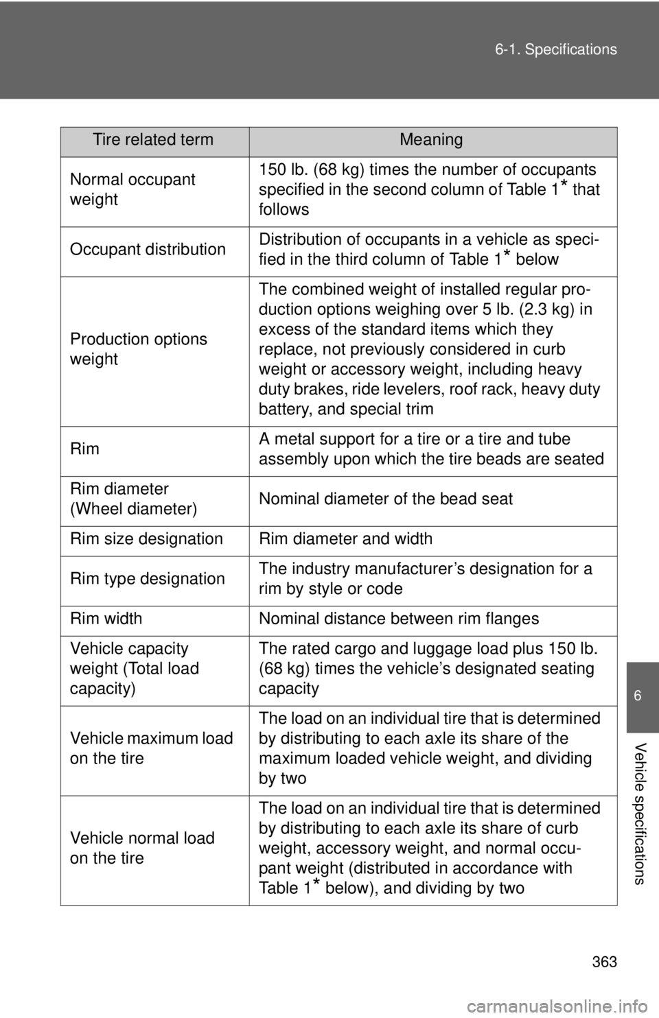
Normal occupant
weight150 lb. (68 kg) times the number of occupants
specified in the second column of Table 1
* that
follows
Occupant distributionDistribution of occupants in a vehicle as speci-
fied in the third column of Table 1
* below
Production options
weight
The combined weight of installed regular pro-
duction options weighing over 5 lb. (2.3 kg) in
excess of the standard items which they
replace, not previously considered in curb
weight or accessory weight, including heavy
duty brakes, ride levelers, roof rack, heavy duty
battery, and special trim
RimA metal support for a tire or a tire and tube
assembly upon which the tire beads are seated
Rim diameter
(Wheel diameter)Nominal diameter of the bead seat
Rim size designationRim diameter and width
Rim type designationThe industry manufacturer’s designation for a
rim by style or code
Rim widthNominal distance between rim flanges
Vehicle capacity
weight (Total load
capacity)The rated cargo and luggage load plus 150 lb.
(68 kg) times the vehicle’s designated seating
capacity
Vehicle maximum load
on the tire
The load on an individual tire that is determined
by distributing to each axle its share of the
maximum loaded vehicle weight, and dividing
by two
Vehicle normal load
on the tire
The load on an individual tire that is determined
by distributing to each axle its share of curb
weight, accessory weight, and normal occu-
pant weight (distributed in accordance with
Ta b l e 1
* below), and dividing by two
Tire related termMeaning
Page 363 of 365
398 What to do if...■Warning lights
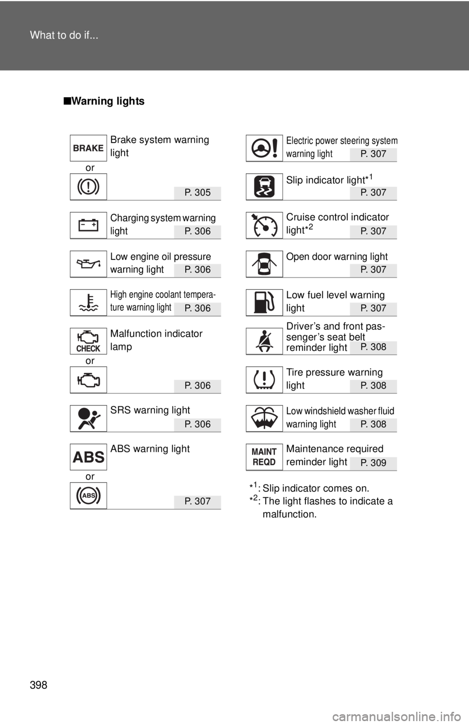
P. 307
or
P. 3 0 5P. 307
P. 3 0 6P. 307
P. 3 0 6P. 307
P. 3 0 6P. 307
P. 308
or
P. 3 0 6P. 308
P. 3 0 6P. 308
P. 309
or*1: Slip indicator comes on.
*2: The light flashes to indicate a malfunction.P. 3 0 7
Brake system warning
lightElectric power steering system
warning light
Slip indicator light*1
Charging system warning
lightCruise control indicator
light*2
Low engine oil pressure
warning lightOpen door warning light
High engine coolant tempera-
ture warning lightLow fuel level warning
light
Malfunction indicator
lamp
Tire pressure warning
light
SRS warning lightLow windshield washer fluid
warning light
ABS warning lightMaintenance required
reminder light
Driver’s and front pas-
senger’s seat belt
reminder light