clock TOYOTA YARIS HATCHBACK 2018 Owners Manual
[x] Cancel search | Manufacturer: TOYOTA, Model Year: 2018, Model line: YARIS HATCHBACK, Model: TOYOTA YARIS HATCHBACK 2018Pages: 520, PDF Size: 8.69 MB
Page 83 of 520
832. Instrument cluster
2
Instrument cluster
Gauges and meters
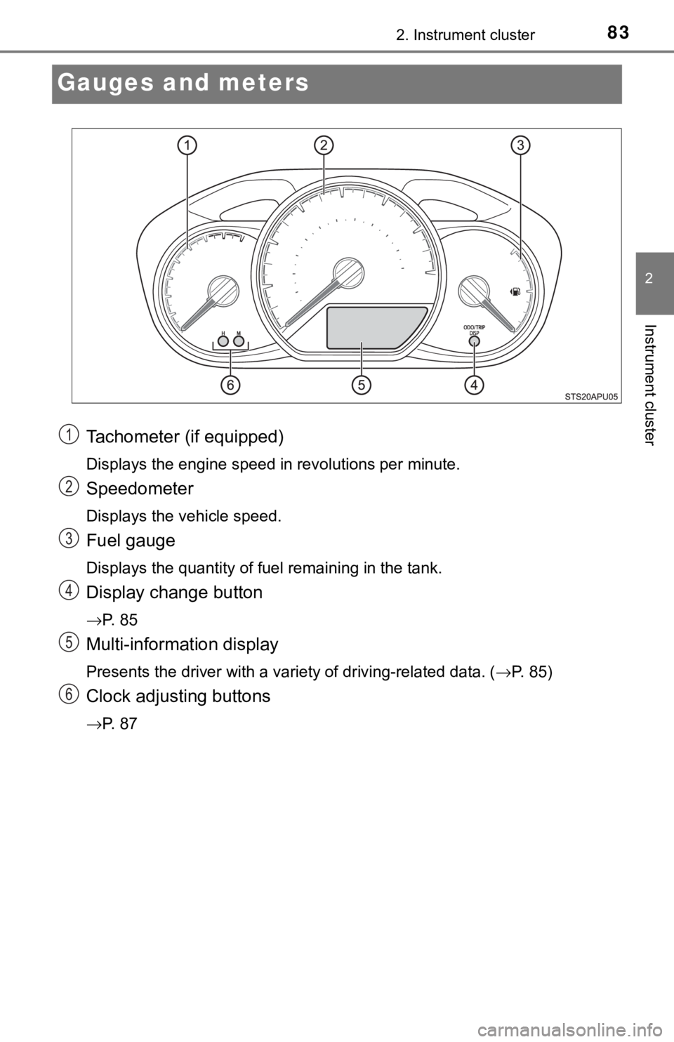
Tachometer (if equipped)
Displays the engine speed in revolutions per minute.
Speedometer
Displays the vehicle speed.
Fuel gauge
Displays the quantity of fuel remaining in the tank.
Display change button
→P. 8 5
Multi-information display
Presents the driver with a variety of driving-related data. (→P. 85)
Clock adjusting buttons
→P. 8 7
1
2
3
4
5
6
Page 85 of 520
852. Instrument cluster
2
Instrument cluster
Multi-information display
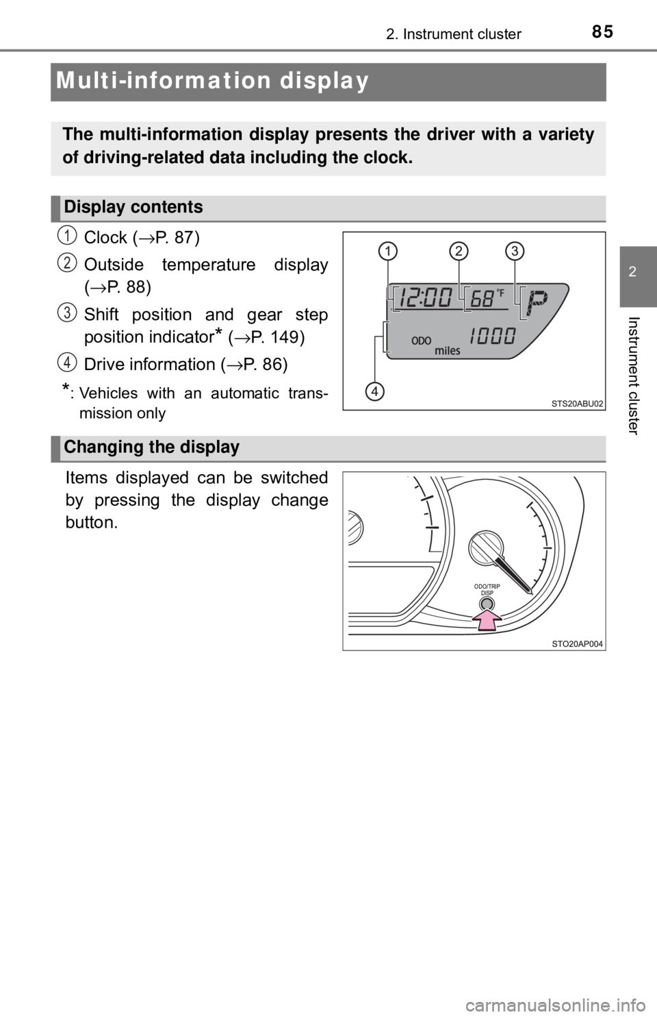
Clock (→P. 87)
Outside temperature display
( → P. 88)
Shift position and gear step
position indicator
* ( → P. 149)
Drive information ( →P. 8 6 )
*: Vehicles with an automatic trans-
mission only
.
Items displayed can be switched
by pressing the display change
button.
The multi-information display pre sents the driver with a variety
of driving-related data including the clock.
Display contents
1
2
3
4
Changing the display
Page 87 of 520
872. Instrument cluster
2
Instrument cluster
Eco Driving Indicator Light can be activated or deactivated by press-
ing the display change button when the Eco Driving Indicator Light
customization display is displayed.
To change the Eco Driving Indicator Light customization display, display the
odometer and press and hold the display change button until the display
changes.
After customization, press the display change button for more than 2 sec-
onds to return to the odometer.
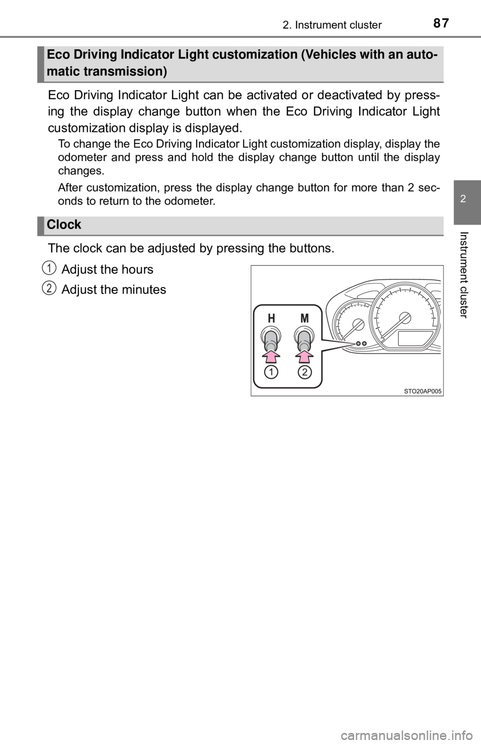
The clock can be adjusted by pressing the buttons.
Adjust the hours
Adjust the minutes
Eco Driving Indicator Light custom ization (Vehicles with an auto-
matic transmission)
Clock
1
2
Page 88 of 520
882. Instrument cluster
The temperature display shows temperatures within the range of
-40°F (-40°C) and 122°F (50°C).
■Display
In the following situations, the correct outside temperature may not
be displayed, or the display may take longer than normal to change:
●When the vehicle is stopped, or moving at low speeds (less than
16 mph [25 km/h])
● When the outside temperature has changed suddenly (at the
entrance/exit of a ga rage, tunnel, etc.)
■When “− −” or “E” is displayed
The system may be malfunctioning. Take your vehicle to your
Toyota dealer.
■ When disconnecting and reco nnecting battery terminals
The following information data will be reset.
● Driving range
● Average fuel consumption
● Average vehicle speed
● Clock data
■ Liquid crystal display
Small spots or light spots may appear on the display. This phenomenon is
characteristic of liquid crystal displa y, and there is no problem continuing to
use the display.
■ Changing the pre-collision warning timing
→P. 181
Outside temperature display
NOTICE
■The multi-information disp lay at low temperatures
Allow the interior of the vehicle to warm up before using the liquid crystal
information display. At extremely low temperatures, the display monitor may
respond slowly, and display changes may be delayed.
Page 320 of 520
3206-1. Using the air conditioning system and defogger
■Adjusting the temperature setting
Vehicles without the button
Turn the temperature control dial clockwise to increase the tem-
perature.
Vehicles with the button
To adjust the temperature setting, turn the temperature control dial
clockwise (warm) or counterclockwise (cool).
If is not pressed, the system will blow ambient temperature air or
heated air.
For quick cooling, turn the temperature control dial to “MAX A/C” posi-
tion and set the outside/recirculated air mode button to recirculated air
mode.
■
Fan speed setting
To adjust the fan speed, turn the fan speed control dial clockwise
(increase) or counterclockwise (decrease).
Turning the dial to “0” turns off the fan.
■
Change the airflow mode
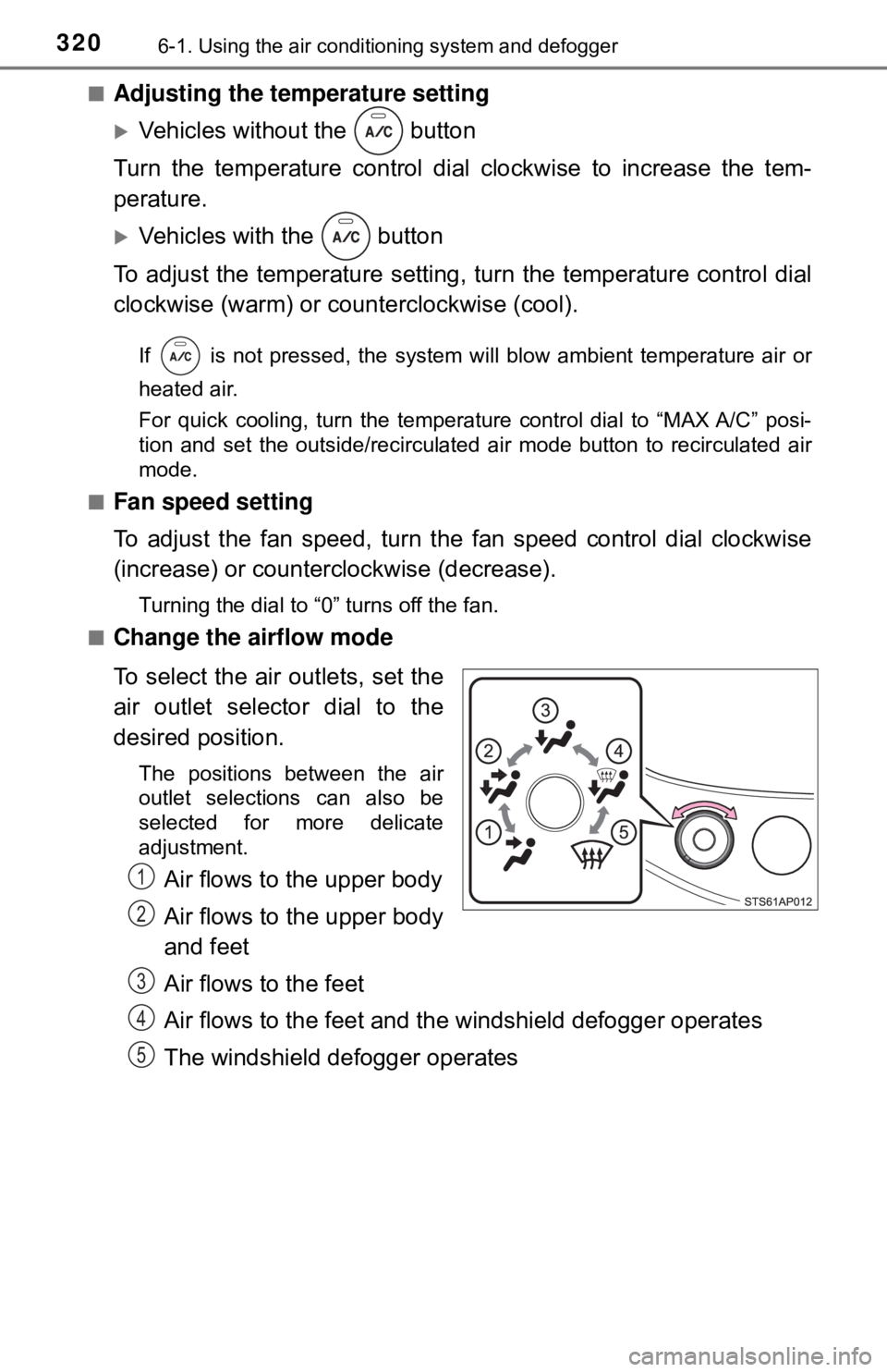
To select the air outlets, set the
air outlet selector dial to the
desired position.
The positions between the air
outlet selections can also be
selected for more delicate
adjustment.
Air flows to the upper body
Air flows to the upper body
and feet
Air flows to the feet
Air flows to the feet and the windshield defogger operates
The windshield defogger operates1
2
3
4
5
Page 362 of 520
3627-3. Do-it-yourself maintenance
■Adding engine oil
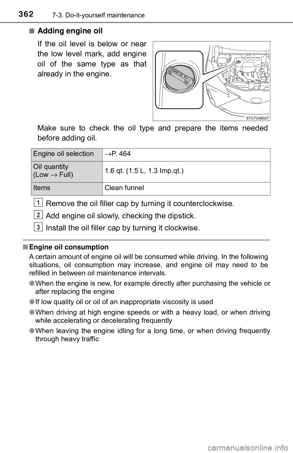
If the oil level is below or near
the low level mark, add engine
oil of the same type as that
already in the engine.
Make sure to check the oil type and prepare the items needed
before adding oil.Remove the oil filler cap by turning it counterclockwise.
Add engine oil slowly, c hecking the dipstick.
Install the oil filler cap by turning it clockwise.
■Engine oil consumption
A certain amount of engine oil will be consumed while driving. In the following
situations, oil consumption may increase, and engine oil may need to be
refilled in between oil maintenance intervals.
●When the engine is new, for example directly after purchasing the vehicle or
after replacing the engine
● If low quality oil or oil of an inappropriate viscosity is used
● When driving at high engine speeds or with a heavy load, or when driving
while accelerating or decelerating frequently
● When leaving the engine idling for a long time, or when driving frequently
through heavy traffic
Engine oil selection →P. 464
Oil quantity
(Low → Full) 1.6 qt. (1.5 L, 1.3 Imp.qt.)
Items
Clean funnel
1
2
3
Page 399 of 520
3997-3. Do-it-yourself maintenance
7
Maintenance and care
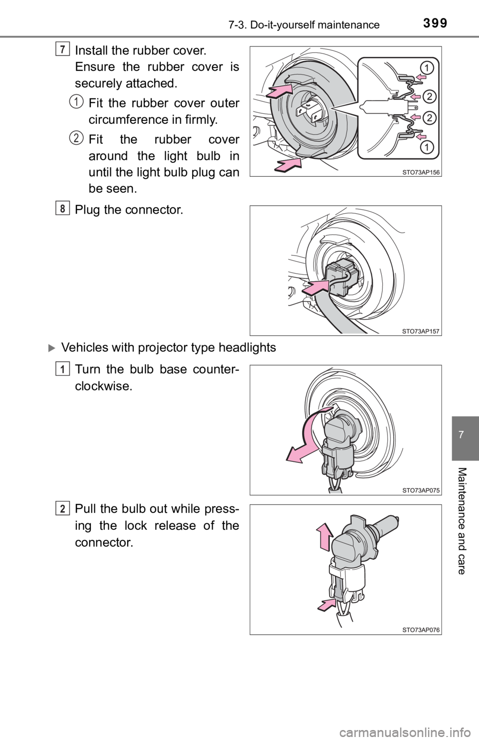
Install the rubber cover.
Ensure the rubber cover is
securely attached.Fit the rubber cover outer
circumference in firmly.
Fit the rubber cover
around the light bulb in
until the light bulb plug can
be seen.
Plug the connector.
Vehicles with proj ector type headlights
Turn the bulb base counter-
clockwise.
Pull the bulb out while press-
ing the lock release of the
connector.
7
1
2
8
1
2
Page 400 of 520
4007-3. Do-it-yourself maintenance
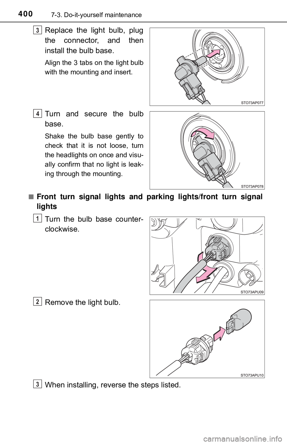
Replace the light bulb, plug
the connector, and then
install the bulb base.
Align the 3 tabs on the light bulb
with the mounting and insert.
Turn and secure the bulb
base.
Shake the bulb base gently to
check that it is not loose, turn
the headlights on once and visu-
ally confirm that no light is leak-
ing through the mounting.
■
Front turn signal lights and pa rking lights/front turn signal
lights
Turn the bulb base counter-
clockwise.
Remove the light bulb.
When installing, reve rse the steps listed.
3
14
1
2
3
Page 401 of 520
4017-3. Do-it-yourself maintenance
7
Maintenance and care
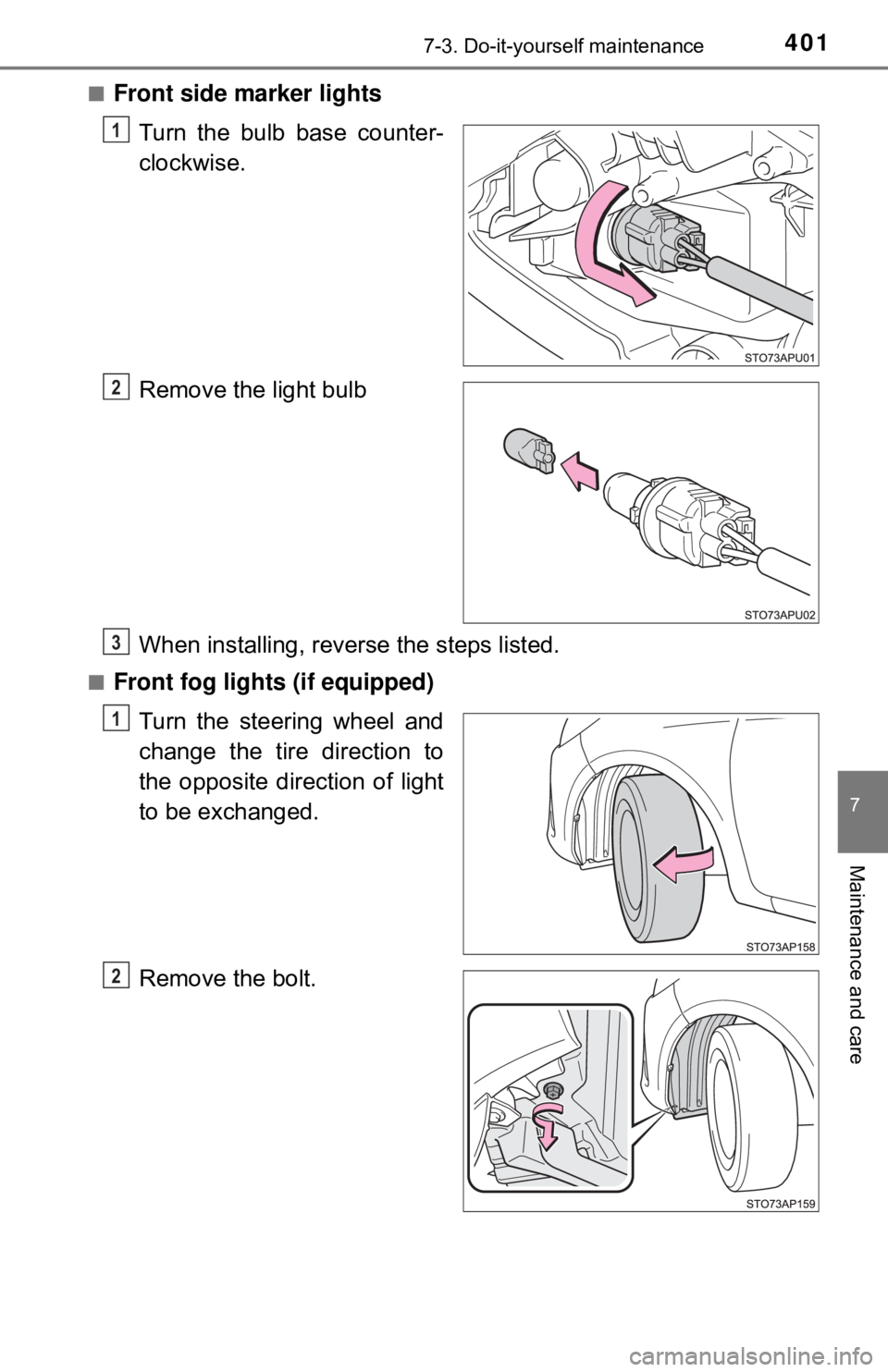
■Front side marker lightsTurn the bulb base counter-
clockwise.
Remove the light bulb
When installing, reve rse the steps listed.
■Front fog lights (if equipped)
Turn the steering wheel and
change the tire direction to
the opposite direction of light
to be exchanged.
Remove the bolt.
1
2
3
1
2
Page 402 of 520
4027-3. Do-it-yourself maintenance
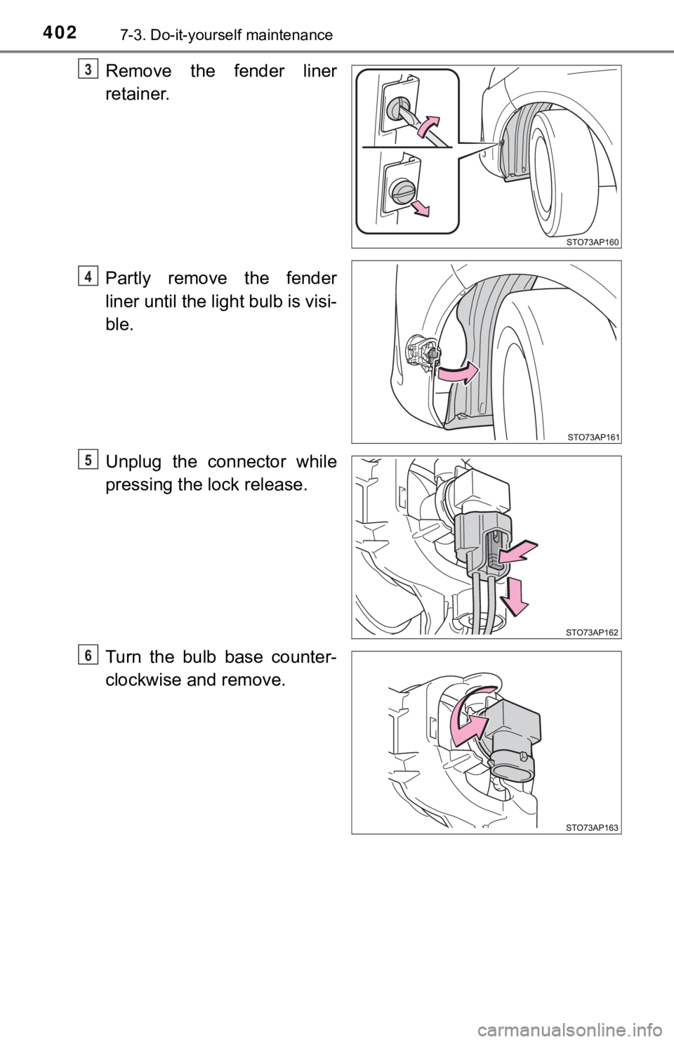
Remove the fender liner
retainer.
Partly remove the fender
liner until the light bulb is visi-
ble.
Unplug the connector while
pressing the lock release.
Turn the bulb base counter-
clockwise and remove.3
4
5
6